first engine swap- LT1/T56
 02-01-2010, 10:17 PM
#201
Junior Member

Join Date: Feb 2010
Posts: 65
Likes: 0
Received 0 Likes
on
0 Posts
Re: first engine swap- LT1/T56
I'm INSPIRED! I've had this VERY clean 88 Camaro kickin around in the garage for a while with no real direction. I also consequently had a LT1 around. I wanted to do the swap but I have never messed with the injected stuff before. I spent the day today after reading a good bit of your project dissassemblin my LT and prepping it for a freshen up. It's really good to see some young people getting dirty and creating some positiveness in the world! If I had someone putting up a project like this at my high school I bet I would have been in less trouble as a youngster. Good job man! I subscribed and can't wait to watch your progress as well as hopefully learn a few things from your adventures!
 02-01-2010, 10:58 PM
#202
Member
Thread Starter
iTrader: (5)
Join Date: May 2009
Location: Washington D.C.
Posts: 496
Likes: 0
Received 0 Likes
on
0 Posts
Car: 1985 Z28
Engine: LT1
Transmission: T56
Axle/Gears: fourth gen 3.42
Re: first engine swap- LT1/T56
thanks, i appreciate it. its been alot of work, but theres still more to do......
i went in and snipped the ls1 pump wiring connector and spliced it in so thats no longer an issue, but i still dont know what to do with the connector/adapter thing that connects the feed out of the pump and the second little fitting on the pump right next to it
i went in and snipped the ls1 pump wiring connector and spliced it in so thats no longer an issue, but i still dont know what to do with the connector/adapter thing that connects the feed out of the pump and the second little fitting on the pump right next to it
02-02-2010, 07:12 AM
#203
Supreme Member

iTrader: (24)
Join Date: Jun 2005
Location: NC
Posts: 7,890
Likes: 0
Received 58 Likes
on
42 Posts
Car: 92 Firebird
Engine: Supercharged 6.0
Transmission: T56
Axle/Gears: 8.8 3.73
Re: first engine swap- LT1/T56
The 3rd gen mounts directly to the hard tube
The LS1 uses a flexible plastic tube which requires the ribs. File them off to fit or cut the metal tube up some and run the flex tubing
The LS1 uses a flexible plastic tube which requires the ribs. File them off to fit or cut the metal tube up some and run the flex tubing
02-02-2010, 01:35 PM
#204
Member
Thread Starter
iTrader: (5)
Join Date: May 2009
Location: Washington D.C.
Posts: 496
Likes: 0
Received 0 Likes
on
0 Posts
Car: 1985 Z28
Engine: LT1
Transmission: T56
Axle/Gears: fourth gen 3.42
Re: first engine swap- LT1/T56
I already ripped up the flex tubing so I guess I'll file it. I just leave the other little fitting uncovered?
02-02-2010, 06:09 PM
#205
Member
Thread Starter
iTrader: (5)
Join Date: May 2009
Location: Washington D.C.
Posts: 496
Likes: 0
Received 0 Likes
on
0 Posts
Car: 1985 Z28
Engine: LT1
Transmission: T56
Axle/Gears: fourth gen 3.42
Re: first engine swap- LT1/T56

got a template made for the fourth gen coolant hole- I should be able to cut it tomorrow. Then my real focus is going to be on:
-getting the fuel tank down and the new sender/lines in
-mounting my new pedals and cutting the shifter hole
-painting the bay
-building my wiring harness
I think these are my four big issues until the new drivetrain gets set in.
edit: i just filed the little nib out of the way on the ls1 pump, and the connecting piece is still hitting the little metal fitting next to the feed outlet. what to do, cut the fitting down?
Last edited by kthxbai; 02-02-2010 at 06:19 PM.
02-02-2010, 08:32 PM
#206
02-02-2010, 10:33 PM
#207
Member
Thread Starter
iTrader: (5)
Join Date: May 2009
Location: Washington D.C.
Posts: 496
Likes: 0
Received 0 Likes
on
0 Posts
Car: 1985 Z28
Engine: LT1
Transmission: T56
Axle/Gears: fourth gen 3.42
Re: first engine swap- LT1/T56

ok well does anything go on that metal nipple? if not ill just chomp it off almost flush and it will fit fine.
I spent about four hours tonight labeling connectors individual wires, and tracing schematics to figure out where my commons are going to be going. I have all of them taped up and straightened out except for the coil/injector groups, and i still have ALT, OIL LEVEL, and REVERSE LIGHTS leftover without any mention of them in my diagrams.
I believe that REVERSE LIGHTS will go up into my existing auto shifter wiring separate from the rest of my wiring, ALT will go to the fuse block? And i have absolutely no idea where OIL LEVEL goes...
 02-03-2010, 04:32 AM
#208
Supreme Member
iTrader: (24)
Join Date: Jun 2005
Location: NC
Posts: 7,890
Likes: 0
Received 58 Likes
on
42 Posts
Car: 92 Firebird
Engine: Supercharged 6.0
Transmission: T56
Axle/Gears: 8.8 3.73
Re: first engine swap- LT1/T56
Injectors and coil are done just like the diagram shows
Alt does connect to the fuse block at the fan fuse but must have a resistor or light bulb soldered inline of pin L. Pin F gets 12v IGN directly
Oil level is not reused
Reverse lights are lengthened to go inside through the firewall and connected to the old auto shifter connector
For the fuel pump, read post #7. After that it goes into the 4th gen tank etc
http://www.ls1tech.com/forums/conver...-gen-tank.html
02-03-2010, 10:23 AM
#209
Member
Thread Starter
iTrader: (5)
Join Date: May 2009
Location: Washington D.C.
Posts: 496
Likes: 0
Received 0 Likes
on
0 Posts
Car: 1985 Z28
Engine: LT1
Transmission: T56
Axle/Gears: fourth gen 3.42
Re: first engine swap- LT1/T56
thanks!
so is it really worth running the reverse lights up around into the bay then back through? i was thinking i was just put them up where the old auto shift cable was, but for the sake of continuity and cleanliness i suppose it wont be too hard to route them up and have the connector end near the pcm connectors...
also, Firebat said that he simply moved the single ALT wire over one terminal in the connector and it worked fine when provided IGN, no resistor needed, has anyone heard of this? he didnt say which way to move it though...
i need to read over the fuel pump thing a few more times, im a bit confused.
Last edited by kthxbai; 02-03-2010 at 12:58 PM.
02-03-2010, 04:37 PM
#210
Supreme Member
iTrader: (24)
Join Date: Jun 2005
Location: NC
Posts: 7,890
Likes: 0
Received 58 Likes
on
42 Posts
Car: 92 Firebird
Engine: Supercharged 6.0
Transmission: T56
Axle/Gears: 8.8 3.73
Re: first engine swap- LT1/T56
Resistor sets you back 90some cents and it known to work. Moving current off of one pin that requires it to one that doesnt hardly seems like an alternative
02-03-2010, 05:06 PM
#211
Member
Thread Starter
iTrader: (5)
Join Date: May 2009
Location: Washington D.C.
Posts: 496
Likes: 0
Received 0 Likes
on
0 Posts
Car: 1985 Z28
Engine: LT1
Transmission: T56
Axle/Gears: fourth gen 3.42
Re: first engine swap- LT1/T56
ok good point. how big of a resistor should it be?
after reading that fuel pump solution i was confused because i dont have a "black bleed line"... all i have is the 3/8 output and the wires. i think i am going to cut that nipple down flush and leave it, i dont see how a compression fitting would work since it will only take up more space
*wiring questions*
something designated "sensor ground" goes directly from a pcm pin to a sensor, without an actual ground connection, correct? I am under the impression it pulls ground from within the pcm from an engine ground pin. I need someone to confirm this so my commons can be drawn out.
i have no idea what red connector "A" pin 1 "CKP Signal" is, it is supposed to be a yellow wire..?
Last edited by kthxbai; 02-03-2010 at 06:52 PM.
02-03-2010, 07:23 PM
#212
Member
Thread Starter
iTrader: (5)
Join Date: May 2009
Location: Washington D.C.
Posts: 496
Likes: 0
Received 0 Likes
on
0 Posts
Car: 1985 Z28
Engine: LT1
Transmission: T56
Axle/Gears: fourth gen 3.42
Re: first engine swap- LT1/T56
ok correct me if I'm wrong but I believe I have found that 1995 LT1 does not have a CKP (crank sensor), so that pin is thrown out.
I still want some reassurance on the sensor ground concept, but I think I have everything under control at this point
I still want some reassurance on the sensor ground concept, but I think I have everything under control at this point
02-03-2010, 08:55 PM
#214
Member
Thread Starter
iTrader: (5)
Join Date: May 2009
Location: Washington D.C.
Posts: 496
Likes: 0
Received 0 Likes
on
0 Posts
Car: 1985 Z28
Engine: LT1
Transmission: T56
Axle/Gears: fourth gen 3.42
Re: first engine swap- LT1/T56

all present and accounted for!
from left- knock, maf, iac, ect, map, vss, iat, tps, rev. lockout, opti, O2, O2, rev. lights

bottom left coil group
above inj groups
on paper towel is alt, temp gauge, oil press. gauge, ign common x 2, gnd common
i think im ready to plug them in and route my wires assuming sensor grounds work like i think they do
02-04-2010, 10:22 PM
#215
Member
Thread Starter
iTrader: (5)
Join Date: May 2009
Location: Washington D.C.
Posts: 496
Likes: 0
Received 0 Likes
on
0 Posts
Car: 1985 Z28
Engine: LT1
Transmission: T56
Axle/Gears: fourth gen 3.42
Re: first engine swap- LT1/T56
siphoned the remaining gas out of my tank today in the lab. we are having the snow storm of the decade starting tomorrow so i will have some downtime to work on the wiring at home (all i have left is to get my alt pigtail updated, still looking for proper resistor info/how to take it apart), and straighten out the ls1 fuel pump/sender which im still mixed up on.
"I used the stock wire on the LT1 harness, put the one red wire from the white plug on the LT1 harness to a 12v switched source with a 480ohm 1w resistor inline (this is needed to keep from burning the alt up) and has been charging for over 2 years now no problems at all." -Klortho
"Mine was the same way, one single skiny wire going to the alternator connector. I tried the resistor thing and blew two alternator so I posted on here and someone responded with this.
"This is a common problem that I luckly avoided.
Here is what I found that helped me save my alt.
I have had my alt. hooked up this way since completing my LT1 swap with no problems and I am using a 95 F-body alt.
Basicly just disconect the wire you are curently using on the L terminal and conect IGN +12 VDC to the F terminal" - Tricked-Out-Toy
^ sounds to me like feeding IGN to pin F on the alt. connector is all i need to do.
i would still like a person who knows whats what to let me know how sensor grounds work so i dont lose my mind
Last edited by kthxbai; 02-04-2010 at 10:54 PM.
02-05-2010, 11:38 AM
#218
Member
Thread Starter
iTrader: (5)
Join Date: May 2009
Location: Washington D.C.
Posts: 496
Likes: 0
Received 0 Likes
on
0 Posts
Car: 1985 Z28
Engine: LT1
Transmission: T56
Axle/Gears: fourth gen 3.42
Re: first engine swap- LT1/T56
alright then I guess a 470 ohm resistor in line of the existing single wire to pin L is how its going to be. That goes to IGN off the fuse block and thats that.
also after double checking my schematics sensor grounds run straight off the pcm to a sensor, no actual gnd involved except through the pcm.
also realized i didnt get relays for my fans, i only bought two for a main relay and a fuel pump relay as per here:
http://lt1swap.com/fuseblock_obd2port.html
anybody have an opinion on how i should set up my fans? i have two 10" plastic fans (aftermarket) that are currently spliced together so you can feed them both power through one set of wires. Should i just run them together as "one" fan?
finally- i have everything else straight with the wiring in my head except the C207 connections. since the car was carbd, i dont have inj. fuses or anything through there. I have found i have nine wires in the C207:
A brown- ALDL/ECM (AIR control)
C wht/grn- light driver/ECM
E wht/blck- ALDL/ECM (test)
F pnk/blck- IGN fuse/EGR-ECM
H tan/blck- ALDL/TCC-ECM
K brown- ECM/VSS
M blck/wht- VSS,p/n switch/GND
N org/blck- ECM/ p/n switch
P ppl- brake/TCC
i could use a hand deciding what goes and what stays. I am assuming pin A is trash (no AIR), pin E is trash (new OBDII diag. port), pin F is trash (will have IGN fuse underhood), pins H+P are trash (no TCC), pin N is trash (going manual)...
so this would potentially leave me with MIL output from PCM to pin C, pins E,K, and M?
all help appreciated.
after looking over my pcm pinouts the only two outputs I have not accounted for are MIL and VSS
~Steven
Last edited by kthxbai; 02-05-2010 at 02:15 PM.
02-05-2010, 03:22 PM
#219
Supreme Member
iTrader: (24)
Join Date: Jun 2005
Location: NC
Posts: 7,890
Likes: 0
Received 58 Likes
on
42 Posts
Car: 92 Firebird
Engine: Supercharged 6.0
Transmission: T56
Axle/Gears: 8.8 3.73
Re: first engine swap- LT1/T56
Running two fans off one wire and one relay will work as long as the wire to the fans can support the load of both
Id bite the bullet and order two more relays and control them independently from the PCM. Its personal preference though, as the single setup will function just fine
The ALDL wiring may be enough, but I dont see the C207 pin J like most 3rd gens reuse for OBDI connections (to ALDL pin M). Either move a wire to ALDL pin J and note its corresponding location in the C207 to route back to the PCM or run an entirely new ALDL connector
You dont want to use a OBDII connector even though you can, and 95 cars did. Even to get your codes checked, a special cable will be required
Pin C - not used
Pin E - ALDL pin B
Pin F - not used, already have one in your new fuseblock
Pin K - not used, your speedo is driven by a cable. Since your old ECM still required a VSS signal, one was sent from the rear of the speedo through this wire to the ECM. Your new PCM has an electric VSS directly wired to it and a speedo signal output. This new signal output drives your cable box, which drives the cable which drives the speedo
Pin M - you need to determine if this is VSS (cruise signal maybe), P/Neutral switch related or cluster related. If you find its a ground for any of them, ground it in the new harness, otherwise leave it open
I missed the little bit on sensor grounds last time, sorry. Sensors are grounded by the ECM/PCM in most cases, but the computer needs to know that it is indeed grounded them to function. This changes the name from ground to low reference, much like how 12v/5v wires are considered 12v or 5v reference in relation to a sensor. If you look over the various control systems for TPI, LT1 and LS1 you will see the technology change as each computer is progressively more powerful, more accurate, and requires more information of the status of all components. TPIs will have sensor grounds that go directly to grounds, LT1's gang groups of low ref wires and send them to 2 PCM pins, and LS1s are fully independent (almost)
In the case of your LT1 and the confusing low ref gangs, try to match the factory service manual clusters
02-05-2010, 03:32 PM
#220
Member
Thread Starter
iTrader: (5)
Join Date: May 2009
Location: Washington D.C.
Posts: 496
Likes: 0
Received 0 Likes
on
0 Posts
Car: 1985 Z28
Engine: LT1
Transmission: T56
Axle/Gears: fourth gen 3.42
Re: first engine swap- LT1/T56
so i am only going to have two wires from my C207?
Pin M to ground
and then Im a bit mixed up on ALDL, pin E will connect to what exactly?
this still also leaves me with the Check Engine Light output from the pcm with no destination
i think i am going to try to do the fans through one relay with 12ga wire, i know the wires spliced from them now are at least that
~Steven
edit: so just after thinking a bit, if i took the wire in the dash harness that would go to pin M and grounded it, could i throw out the C207 entirely if i ran a new ALDL connector?
as far as i know all a new one would need is serial from the pcm, field enable from the pcm, +12v, and ground
02-05-2010, 03:54 PM
#221
Supreme Member
iTrader: (24)
Join Date: Jun 2005
Location: NC
Posts: 7,890
Likes: 0
Received 58 Likes
on
42 Posts
Car: 92 Firebird
Engine: Supercharged 6.0
Transmission: T56
Axle/Gears: 8.8 3.73
Re: first engine swap- LT1/T56
MIL will always be there. You can replace the C207 with a smaller inline connector, but some wires must remain
D20 wht/blk to ALDL B
D30 tan to ALDL M
Non PCM wires can be ran from anywhere
D20 wht/blk to ALDL B
D30 tan to ALDL M
Non PCM wires can be ran from anywhere
02-05-2010, 04:08 PM
#222
Member
Thread Starter
iTrader: (5)
Join Date: May 2009
Location: Washington D.C.
Posts: 496
Likes: 0
Received 0 Likes
on
0 Posts
Car: 1985 Z28
Engine: LT1
Transmission: T56
Axle/Gears: fourth gen 3.42
Re: first engine swap- LT1/T56
so does MIL go to pin C the one labeled "light driver"?
and you are implying that to use my existing port PCM serial data goes to pin H which will go to ALDL M, and PCM field enable goes to pin E which will go to ALDL B?
also, where would the existing aldl port be in my car? i have never looked for it.
and you are implying that to use my existing port PCM serial data goes to pin H which will go to ALDL M, and PCM field enable goes to pin E which will go to ALDL B?
also, where would the existing aldl port be in my car? i have never looked for it.
Last edited by kthxbai; 02-05-2010 at 04:12 PM.
02-05-2010, 05:16 PM
#223
Supreme Member
iTrader: (24)
Join Date: Jun 2005
Location: NC
Posts: 7,890
Likes: 0
Received 58 Likes
on
42 Posts
Car: 92 Firebird
Engine: Supercharged 6.0
Transmission: T56
Axle/Gears: 8.8 3.73
Re: first engine swap- LT1/T56
Yes, MIL is pin C on all other years
Stock ALDL is under the steering column, either at the edge of the hush panel or behind it
Confirm the pin locations with a multimeter before you complete the isntall
Stock ALDL is under the steering column, either at the edge of the hush panel or behind it
Confirm the pin locations with a multimeter before you complete the isntall
02-05-2010, 05:28 PM
#224
Member
Thread Starter
iTrader: (5)
Join Date: May 2009
Location: Washington D.C.
Posts: 496
Likes: 0
Received 0 Likes
on
0 Posts
Car: 1985 Z28
Engine: LT1
Transmission: T56
Axle/Gears: fourth gen 3.42
Re: first engine swap- LT1/T56
ok great

so serial will go to pin M through C207 E, and then I can move the TCC pin to wherever i need and then connect to C207 H. got it
now i have every single wire labeled and understood, except the fan relay which ill order up.
i must admit its a great feeling to get to this point in the wiring! thanks as always Pocket and others
the only other thing I have home with me to work on is the fuel sender, so here is what im doing...
I read the post about the venturi pressure release, and looked up how the venturi worked with the fuel bucket. I am under the impression that adding a line off of that port with a hole in the end is no different than leaving it open as it is. to make room for the nipple to stay uncovered, i am going to use 3/8" fuel line with a hose clamp and the ls1 pump's ribs to connect the output. Then i toss the filter bag on the bottom of the pump and done.
the only last thing about that is which of the four fuel lines coming from the sender is which, and how can i handle them without hooking up charcoal etc. feed and return get my new lines, but can the other two just sit uncovered?
~Steven
Last edited by kthxbai; 02-05-2010 at 05:40 PM.
02-05-2010, 05:58 PM
#225
Supreme Member
iTrader: (24)
Join Date: Jun 2005
Location: NC
Posts: 7,890
Likes: 0
Received 58 Likes
on
42 Posts
Car: 92 Firebird
Engine: Supercharged 6.0
Transmission: T56
Axle/Gears: 8.8 3.73
Re: first engine swap- LT1/T56
https://www.thirdgen.org/forums/ltx-...turn-line.html
EVAP should be capped if you arent using a canister, but dont forget to use a vented gascap
Other 3 are required, the vent is the white filter looking thing hanging down
EVAP should be capped if you arent using a canister, but dont forget to use a vented gascap
Other 3 are required, the vent is the white filter looking thing hanging down
02-05-2010, 07:58 PM
#226
Member
Thread Starter
iTrader: (5)
Join Date: May 2009
Location: Washington D.C.
Posts: 496
Likes: 0
Received 0 Likes
on
0 Posts
Car: 1985 Z28
Engine: LT1
Transmission: T56
Axle/Gears: fourth gen 3.42
Re: first engine swap- LT1/T56
ok cool i just bought the vented cap.
do i need a white filter looking thing for my vent line too?
also any thoughts on the venturi?
do i need a white filter looking thing for my vent line too?
also any thoughts on the venturi?
Last edited by kthxbai; 02-05-2010 at 08:02 PM.
02-08-2010, 11:37 PM
#227
Member
Thread Starter
iTrader: (5)
Join Date: May 2009
Location: Washington D.C.
Posts: 496
Likes: 0
Received 0 Likes
on
0 Posts
Car: 1985 Z28
Engine: LT1
Transmission: T56
Axle/Gears: fourth gen 3.42
Re: first engine swap- LT1/T56

got some fuel hose and a clamp on the sender so thats ready to go.
easy questions- are the wires in the LT1 harness 18 gauge?
should i snip the connector off of the fuel sender and solder wires in or should i buy a corresponding female side?
is a rubber vacuum cap ok to put on the evap line or will the fumes eat it away?
02-09-2010, 07:38 AM
#228
Supreme Member
iTrader: (24)
Join Date: Jun 2005
Location: NC
Posts: 7,890
Likes: 0
Received 58 Likes
on
42 Posts
Car: 92 Firebird
Engine: Supercharged 6.0
Transmission: T56
Axle/Gears: 8.8 3.73
Re: first engine swap- LT1/T56
Fuel pump wires are 16ga
The sender should have a single wire to it which is a female spade terminal. Either reuse it and the length of wire or find a new one
Cap the line with some sort of fuel safe rubber plug. Any parts store should have plenty. If you cant find what you want, use another of the big white vent things
The sender should have a single wire to it which is a female spade terminal. Either reuse it and the length of wire or find a new one
Cap the line with some sort of fuel safe rubber plug. Any parts store should have plenty. If you cant find what you want, use another of the big white vent things
02-10-2010, 05:01 PM
#229
Member
Thread Starter
iTrader: (5)
Join Date: May 2009
Location: Washington D.C.
Posts: 496
Likes: 0
Received 0 Likes
on
0 Posts
Car: 1985 Z28
Engine: LT1
Transmission: T56
Axle/Gears: fourth gen 3.42
Re: first engine swap- LT1/T56
so i started working on my fuse block today, and I have managed to confuse myself a bit.
According to my schematics here is what i have found:
PCM battery feed needs a 10A fuse
fuel pump relay needs a 15A fuse
INJ 1 group needs a 7.5A fuse
INJ 2 group needs a 7.5A fuse
PCM IGN feed needs a 15A fuse
MAF needs a 15A fuse
both O2 sensors need a 10A fuse
rev. lockout needs a 10A fuse
ICM needs a 10A fuse
fan relay needs a 10A fuse
so with that, how should i distribute these connections to four fuses- one battery hot at all times, the other three IGN hot?
my hot at all times fuse (#1) will feed my pcm and the fuel relay (and the fan relay?)
IGN fuses (#s 2,3,4) will feed everything that needs IGN, but if two of them are for the injectors, how does this work?
I have seen blocks with only four fuses running everything that I am, so I would appreciate some help figuring out what to overlap etc. I can always add more fuses, but I dont know if it is absolutely necessary.
*edit: just had a doh! moment- so I can add multiple circuits and also add up their current and put a bigger fuse (for example the two IGN 7.5 could go to a single 15A fuse). So I guess what I really need is help on which circuits to put together and on which fuses.
~Steven
Last edited by kthxbai; 02-10-2010 at 05:34 PM.
02-10-2010, 05:55 PM
#230
Supreme Member
iTrader: (24)
Join Date: Jun 2005
Location: NC
Posts: 7,890
Likes: 0
Received 58 Likes
on
42 Posts
Car: 92 Firebird
Engine: Supercharged 6.0
Transmission: T56
Axle/Gears: 8.8 3.73
Re: first engine swap- LT1/T56
Most of those circuits are doubled up or tripled up
10A INJ 1
10A INJ 2
15A PCM/MAF IGN
10A Coil
10A Fans/Alt
10A Trans stuff
20A PCM/Fuel pump relay, battery 12v constant - separate from the fuseblock
Stock 3rd gen has a small fuse holder near the battery, I see no reason not to reuse this
10A INJ 1
10A INJ 2
15A PCM/MAF IGN
10A Coil
10A Fans/Alt
10A Trans stuff
20A PCM/Fuel pump relay, battery 12v constant - separate from the fuseblock
Stock 3rd gen has a small fuse holder near the battery, I see no reason not to reuse this
02-13-2010, 01:26 PM
#231
Member
Thread Starter
iTrader: (5)
Join Date: May 2009
Location: Washington D.C.
Posts: 496
Likes: 0
Received 0 Likes
on
0 Posts
Car: 1985 Z28
Engine: LT1
Transmission: T56
Axle/Gears: fourth gen 3.42
Re: first engine swap- LT1/T56

none of the parts places around here had a good vent filter so i got one of the generic breathers and stuck it on- I will cap the evap line in school.

started working on the fuse block and relays- waiting for a few more pieces to come in.

general question: for the ground for the relays and a few other places, can i just run that to the frame?
Last edited by kthxbai; 02-13-2010 at 01:45 PM.
02-14-2010, 07:16 AM
#232
Supreme Member
iTrader: (24)
Join Date: Jun 2005
Location: NC
Posts: 7,890
Likes: 0
Received 58 Likes
on
42 Posts
Car: 92 Firebird
Engine: Supercharged 6.0
Transmission: T56
Axle/Gears: 8.8 3.73
Re: first engine swap- LT1/T56
Ground them to the engine harness grounds. Keep in mind the fuel and IGN relays will use a GRD, while the fans are grounded by the PCM
02-14-2010, 10:10 AM
#233

Re: first engine swap- LT1/T56
I think where I got this idea of just moving the wire over was from looking at the alternator on my 92 firebird v6. It had the same connector as the LT1 but the wire was in a different location. So, used a really small screwdriver to bend the pin connector for the wire to get the wire out of the connector, took the wire out, bent the pin back, and put it in the same slot as was on the thirdgen(92 v6) setup, and music came from the heavens because my voltage gauge worked. I'll try to take a pic of my 92 alternator connector today if I can. My LT1 car is in storage and I think I ended up moving the wire back since I installed a 4th gen dash.
Last edited by Firebat; 02-14-2010 at 06:06 PM.
02-14-2010, 05:52 PM
#234
Member
Thread Starter
iTrader: (5)
Join Date: May 2009
Location: Washington D.C.
Posts: 496
Likes: 0
Received 0 Likes
on
0 Posts
Car: 1985 Z28
Engine: LT1
Transmission: T56
Axle/Gears: fourth gen 3.42
Re: first engine swap- LT1/T56
thanks Firebat- for now I am planning on the inline resistor I just havent found a local place that has it in 1 watt yet. In other news I am trying to buy a set of autometer gauges to solve my cablex problem. New fuse block came today so I am rigging it up tonight. Tomorrow I should be able to go in to the engine and mock up the new harness. Then I can get down to the grindstone and extend all my wires for the interior pcm location.
~Steven
~Steven
02-15-2010, 11:52 AM
#235
Member
Thread Starter
iTrader: (5)
Join Date: May 2009
Location: Washington D.C.
Posts: 496
Likes: 0
Received 0 Likes
on
0 Posts
Car: 1985 Z28
Engine: LT1
Transmission: T56
Axle/Gears: fourth gen 3.42
Re: first engine swap- LT1/T56
another general question, where should i put my new fuse block/relays, as well as the power distribution block? I started plugging up my new harness today but before i do alot of the non-pcm connections i need to know where i am routing all this stuff. Suggestions?
02-15-2010, 01:20 PM
#236
Supreme Member
iTrader: (24)
Join Date: Jun 2005
Location: NC
Posts: 7,890
Likes: 0
Received 58 Likes
on
42 Posts
Car: 92 Firebird
Engine: Supercharged 6.0
Transmission: T56
Axle/Gears: 8.8 3.73
Re: first engine swap- LT1/T56
Inner fender is common for the fuse block and the B-body box should already be angled to fit it
Power dist block can go anywhere you want. Usually its near the battery for the shortest cables
Power dist block can go anywhere you want. Usually its near the battery for the shortest cables
02-15-2010, 10:20 PM
#237
Member
Thread Starter
iTrader: (5)
Join Date: May 2009
Location: Washington D.C.
Posts: 496
Likes: 0
Received 0 Likes
on
0 Posts
Car: 1985 Z28
Engine: LT1
Transmission: T56
Axle/Gears: fourth gen 3.42
Re: first engine swap- LT1/T56

heres my (nearly) complete fuse block and relays
1- PCM + fuel relay battery hot
2- PCM + MAF ign feed
3- INJ 1
4- INJ 2
5- O2s and Trans.
6- coil
7- fans + alt
fuel pump relay, IGN relay, fans relay
I'm waiting on a few terminals to be mailed to me so i can finish this up- what I did since i dont have the car set up yet is just gave myself a foot long wire out of each terminal, labeled it, and will splice to that when the time comes.
~Steven
 02-16-2010, 06:06 PM
#240
Member
Thread Starter
iTrader: (5)
Join Date: May 2009
Location: Washington D.C.
Posts: 496
Likes: 0
Received 0 Likes
on
0 Posts
Car: 1985 Z28
Engine: LT1
Transmission: T56
Axle/Gears: fourth gen 3.42
Re: first engine swap- LT1/T56

fitting all my connectors...

a few things to mention- for now I am just running the single knock sensor wire along right above the starter and then up along where the bellhousing will be, and the temp (gauge) wire off the block up through where the headers will be, are these routes ok?
thanks for the compliments guys!
~Steven
02-16-2010, 07:27 PM
#241
Supreme Member
iTrader: (3)
Join Date: May 2004
Location: Kingsport Tenn
Posts: 1,036
Likes: 0
Received 0 Likes
on
0 Posts
Car: 1992 camaro
Engine: LT1
Transmission: 4L60E
Axle/Gears: 3:73
Re: first engine swap- LT1/T56
IMHO wiring can make or brake a swap,looks like you are taking the time to make it look good.
02-16-2010, 09:11 PM
#242
Member
Thread Starter
iTrader: (5)
Join Date: May 2009
Location: Washington D.C.
Posts: 496
Likes: 0
Received 0 Likes
on
0 Posts
Car: 1985 Z28
Engine: LT1
Transmission: T56
Axle/Gears: fourth gen 3.42
Re: first engine swap- LT1/T56
thanks- i took the headers and test fit them with the wires and answered my own questions. Im going to take the temp wire and bring it up by the coil and over the valve covers with everything else, and try to bring the knock sensor wire up by the alternator and do the same. I'm not trying to have any melted wires
02-16-2010, 09:56 PM
#243
Supreme Member
iTrader: (24)
Join Date: Jun 2005
Location: NC
Posts: 7,890
Likes: 0
Received 58 Likes
on
42 Posts
Car: 92 Firebird
Engine: Supercharged 6.0
Transmission: T56
Axle/Gears: 8.8 3.73
Re: first engine swap- LT1/T56
There should be a plug on the drivers side which usually clears headers better than the pass side knock sensor
02-17-2010, 06:41 PM
#244
Member
Thread Starter
iTrader: (5)
Join Date: May 2009
Location: Washington D.C.
Posts: 496
Likes: 0
Received 0 Likes
on
0 Posts
Car: 1985 Z28
Engine: LT1
Transmission: T56
Axle/Gears: fourth gen 3.42
Re: first engine swap- LT1/T56

knock sensor re-routed

temp sensor looping around up by the ICM

re-taped everything with trans connections and O2s in.
also got the 470 ohm 2 watt resistor i needed from the electronics lab at school
 02-18-2010, 05:53 PM
#245
Member
Thread Starter
iTrader: (5)
Join Date: May 2009
Location: Washington D.C.
Posts: 496
Likes: 0
Received 0 Likes
on
0 Posts
Car: 1985 Z28
Engine: LT1
Transmission: T56
Axle/Gears: fourth gen 3.42
Re: first engine swap- LT1/T56
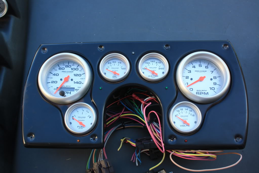
well i just bought a set of autometer gauges off of a member here- i cant wait to wire them in. just a quick question- is the LT1 VSS and tach feed compatible with autometers specifications:
"Speedometer Senders
The speedometer is designed to operate with an electrical speed sender. The speed sender signal range must be between 500 and 400,000
pulses/mile (310 and 248,500 pulses/km). Any speed sender or electronic module that meets the following two conditions can be used:
1. Pulse rate generated is proportional to vehicle speed.
2. Output voltage within the ranges listed below:
• 4 to 16V (Hall effect sender, 3-wire)
• 4 to 120V peak to peak into a 10K ohm load (Sine wave generator, 2-wire)
• 5V Square wave (TTL)"
tach needs a 4 pulse signal?
~Steven
02-18-2010, 06:28 PM
#246
Supreme Member
iTrader: (24)
Join Date: Jun 2005
Location: NC
Posts: 7,890
Likes: 0
Received 58 Likes
on
42 Posts
Car: 92 Firebird
Engine: Supercharged 6.0
Transmission: T56
Axle/Gears: 8.8 3.73
Re: first engine swap- LT1/T56
The LT1 PCM outputs a 4,000ppm signal for the speedo, just like 3rd gens, and LSx PCMs for that matter. Move it to that setting
Not sure on the tach, hook it to the PCM tach output and see what happens
Not sure on the tach, hook it to the PCM tach output and see what happens
02-18-2010, 08:37 PM
#247
Member
Thread Starter
iTrader: (5)
Join Date: May 2009
Location: Washington D.C.
Posts: 496
Likes: 0
Received 0 Likes
on
0 Posts
Car: 1985 Z28
Engine: LT1
Transmission: T56
Axle/Gears: fourth gen 3.42
Re: first engine swap- LT1/T56
excellent, i doubt i will have any problems once i get it wired in properly. tomorrow im going to try and get my fourth gen pedals mocked in and cut my new clutch master hole etc. After that ill take them back out so the brake booster is out of the way for paint if it ever goes above freezing here 
~Steven
~Steven
02-18-2010, 09:38 PM
#248
Member
iTrader: (1)
Join Date: Aug 2007
Location: Leicester,Ma.
Posts: 483
Likes: 0
Received 0 Likes
on
0 Posts
Car: 1988 TA
Engine: TPI 350
Transmission: auto
Axle/Gears: 3.27's
Re: first engine swap- LT1/T56
i know how you feel..ive been planning my LT1 project around the weather lately..too damn cold out.
02-18-2010, 10:05 PM
#249
Supreme Member
Re: first engine swap- LT1/T56
ya, the cold weather sucks, it's been holding my LT1 swap back also.
02-19-2010, 12:44 PM
#250
Member
iTrader: (1)

Join Date: Nov 2008
Location: Lynchburg, VA
Posts: 109
Likes: 0
Received 0 Likes
on
0 Posts
Car: 92 RS
Engine: 305 TBI
Transmission: T-5
Axle/Gears: 4th Gen/3.23/Posi
Re: first engine swap- LT1/T56
Love the gauge setup - How much did that set ya back? Your progress is comin along great, man...