LS1/6 build and swap .. so long SBC
 06-26-2011, 12:22 PM
#51
Re: LS1/6 build and swap .. so long SBC
Thanks guys, hope the coil location works out as well once I get the engine in place and the wires ran. After seeing some of the clean engine bay wiring jobs on this site, it has driven me to create a cleaner install myself while I have the opportunity.
Been real busy with work so haven't had much chance to provide many updates, but some progress, both good and bad has been happening.
First up is the Comp Cam trunion upgrade of the LS1 rocker arms. Installation instructions are quite simple, but the upgrade is not quite as straight forward as expected. Of the 16 rocker arms upgrade, all but 2 turned out great, with the other two having binding issues. I will be working on resolving these two before engine start up, but in the mean time wanted to inform other of the issues that can arise. Seems I am not the only one who has run into these problems. For more information on this upgrade check out the following thread..
http://www.ls1tech.com/forums/genera...l-problem.html
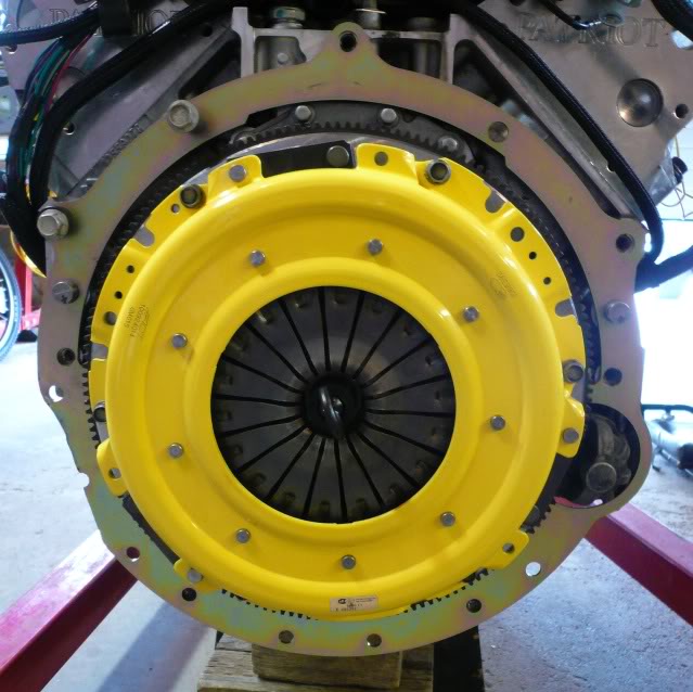
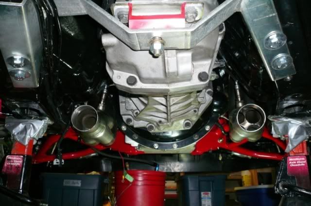
Next, I got the new Quicktime RM-8020 bell installed with a used Ram Powergrip HD clutch which I picked up for a good price with an RAM SFI billet flywheel. Budget constraints were preventing the twin disc clutch I really wanted. With the bell installed, I checked the centering of the bell with crank center and found things out about 0.015" from center = 0.0075� run out. Installed some Lakewood offset dowels and got her centered to 0.003" from center = 0.0015� run out, well within the 0.005� maximum run out the manufacturers specify.

Once the bell was installed and all lined up, I did a test fit of the headers. With the bell as received, the passenger side header fit without issue, but the driver side had some major clearance problems. The driver side could not even be bolted up with the interference. These headers are the Hawks/Stainless Works with 2" primary and 3" collector version.
With some sawzall work and a bit if clean up grinding, it was time to move on.
With the engine wiring and N2O portion of the wiring now complete, needing only to add in the additional wiring for the 4th Gen cruise and A/C, I decided to test fit the T56 to the bell to ensure I had sufficient throw out bearing clearance. Itching to get this engine in that engine bay! As luck would have it, this used clutch is a little too worn to install, measuring 0.200� of pressure on the clutch fingers with the throw out bearing fully compressed. For those wondering how to check this clearance, here is my favorite explanation of the process:
http://www.ls1tech.com/forums/manual-transmission/1030815-does-your-clutch-setup-need-shim.html
Not wanting to believe the clutch was toast, I also went through RAM clutches procedure which winded up with an even worse reading.
http://www.ramclutches.com/Instructions/Factory%20Hyd%20Setup.htm
Make sure you follow the worksheet, as I didn�t notice it existed until I after talked with tech support.
http://www.ramclutches.com/Instructions/FACTORYBEARINGPOSITION1010.pdf
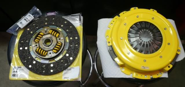
Old clutch is being removed and filed today, with a new ACT clutch going in. The ACT clutch is rated for 725 ft/lbs of torque so should be suitable for my application. Really wanted to go with a Monster, but she is a pretty penny to get here shipped north of the border. Off to the garage �
Been real busy with work so haven't had much chance to provide many updates, but some progress, both good and bad has been happening.
First up is the Comp Cam trunion upgrade of the LS1 rocker arms. Installation instructions are quite simple, but the upgrade is not quite as straight forward as expected. Of the 16 rocker arms upgrade, all but 2 turned out great, with the other two having binding issues. I will be working on resolving these two before engine start up, but in the mean time wanted to inform other of the issues that can arise. Seems I am not the only one who has run into these problems. For more information on this upgrade check out the following thread..
http://www.ls1tech.com/forums/genera...l-problem.html
Next, I got the new Quicktime RM-8020 bell installed with a used Ram Powergrip HD clutch which I picked up for a good price with an RAM SFI billet flywheel. Budget constraints were preventing the twin disc clutch I really wanted. With the bell installed, I checked the centering of the bell with crank center and found things out about 0.015" from center = 0.0075� run out. Installed some Lakewood offset dowels and got her centered to 0.003" from center = 0.0015� run out, well within the 0.005� maximum run out the manufacturers specify.
Once the bell was installed and all lined up, I did a test fit of the headers. With the bell as received, the passenger side header fit without issue, but the driver side had some major clearance problems. The driver side could not even be bolted up with the interference. These headers are the Hawks/Stainless Works with 2" primary and 3" collector version.
With some sawzall work and a bit if clean up grinding, it was time to move on.
With the engine wiring and N2O portion of the wiring now complete, needing only to add in the additional wiring for the 4th Gen cruise and A/C, I decided to test fit the T56 to the bell to ensure I had sufficient throw out bearing clearance. Itching to get this engine in that engine bay! As luck would have it, this used clutch is a little too worn to install, measuring 0.200� of pressure on the clutch fingers with the throw out bearing fully compressed. For those wondering how to check this clearance, here is my favorite explanation of the process:
http://www.ls1tech.com/forums/manual-transmission/1030815-does-your-clutch-setup-need-shim.html
Not wanting to believe the clutch was toast, I also went through RAM clutches procedure which winded up with an even worse reading.
http://www.ramclutches.com/Instructions/Factory%20Hyd%20Setup.htm
Make sure you follow the worksheet, as I didn�t notice it existed until I after talked with tech support.
http://www.ramclutches.com/Instructions/FACTORYBEARINGPOSITION1010.pdf
Old clutch is being removed and filed today, with a new ACT clutch going in. The ACT clutch is rated for 725 ft/lbs of torque so should be suitable for my application. Really wanted to go with a Monster, but she is a pretty penny to get here shipped north of the border. Off to the garage �
 07-06-2011, 11:51 PM
#52
Re: LS1/6 build and swap .. so long SBC
Got the worn out clutch removed and installed a fresh ACT GM9-HDSS. Clutch is rated for 725 ft/lbs so should be able to handle the power I plan to put down.
The clutch and pressure plate is Spec 1.1 certified as well.
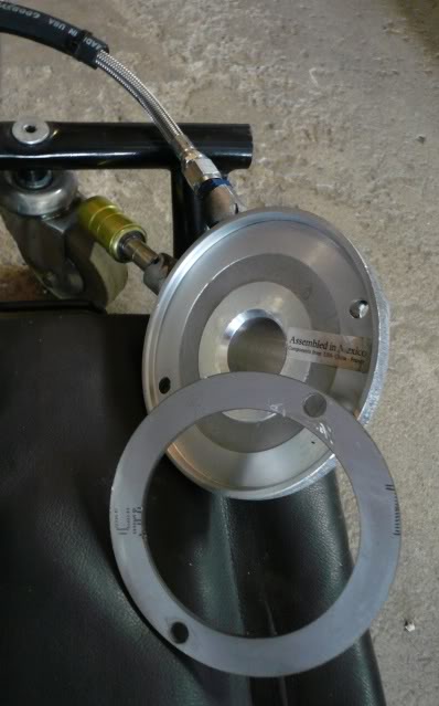
With the new clutch installed I ended up having to install the custom slave cylinder spacer I used with the 406 / T56 connection previously. Had this custom fabbed at a sign store that does water jet cutting for a $20.
Remote bleeder line is long enough to reach up near the brake reservoir and really makes the clutch bleeding easy.
The slave will be connecting up to a Tick Performance master cylinder.
Got the engine and tranny installed and now have the next hurdle with an alignment issue between the BMR LS1 conversion K member and the solid Motovative Perofmance engine mounts.
The mounts are to be exact replacements for the stock mounts so we will see where this one goes ...
The clutch and pressure plate is Spec 1.1 certified as well.
With the new clutch installed I ended up having to install the custom slave cylinder spacer I used with the 406 / T56 connection previously. Had this custom fabbed at a sign store that does water jet cutting for a $20.
Remote bleeder line is long enough to reach up near the brake reservoir and really makes the clutch bleeding easy.
The slave will be connecting up to a Tick Performance master cylinder.
Got the engine and tranny installed and now have the next hurdle with an alignment issue between the BMR LS1 conversion K member and the solid Motovative Perofmance engine mounts.
The mounts are to be exact replacements for the stock mounts so we will see where this one goes ...
 10-09-2011, 04:04 PM
#55
Re: LS1/6 build and swap .. so long SBC
Wow � been quite a long time since my last post but some progress has been going on � With having a reeaal busy summer with not much time to work on the car, this is turning into a winter project now. At least, this will help make sure no short cuts are taken.
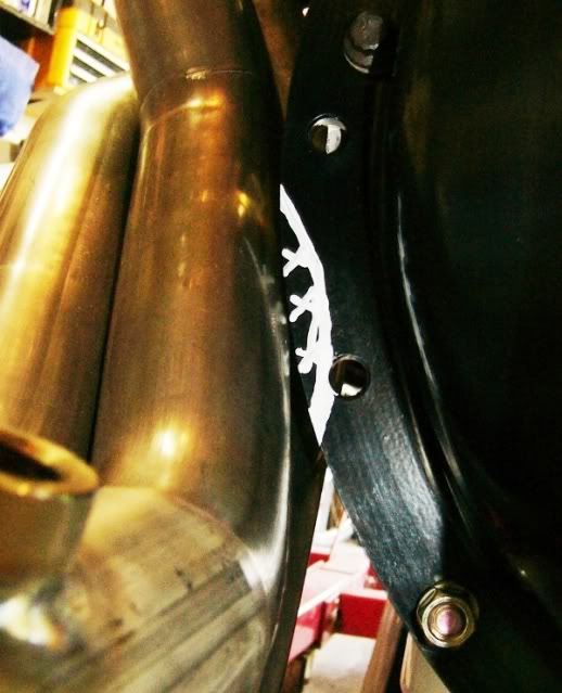
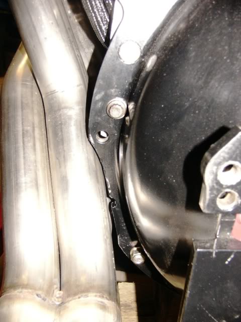
After discussing my engine mount issue with BMR, they indicated this is the reason they don�t build solid motor mounts. With no movement in the BMR k-member mounts and very little play to get things lined up with the solid mounts, it was time for plan B. The tranny is sitting on the cross member here.
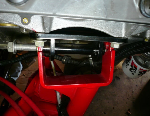
I had to switch back to a set of stock motor mounts. With the stock mounts in place everything bolted up just fine.
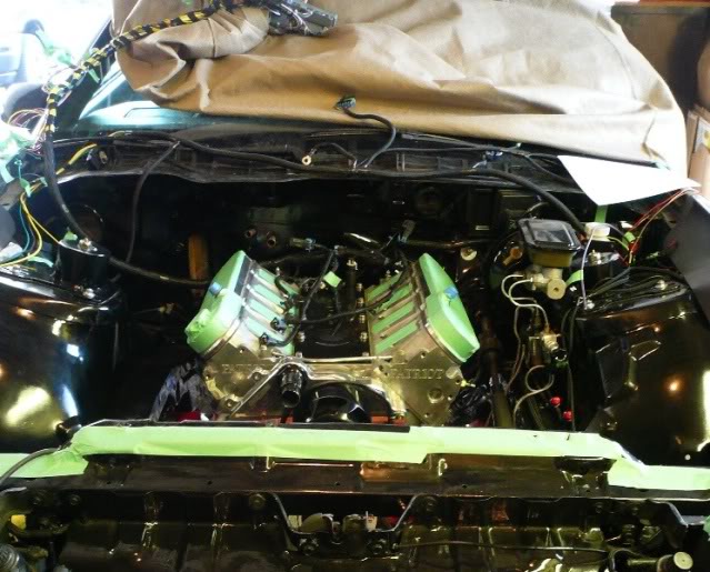
These rubber mounts are looking a little weak though, might have to upgrade them to poly�s.
After discussing my engine mount issue with BMR, they indicated this is the reason they don�t build solid motor mounts. With no movement in the BMR k-member mounts and very little play to get things lined up with the solid mounts, it was time for plan B. The tranny is sitting on the cross member here.
I had to switch back to a set of stock motor mounts. With the stock mounts in place everything bolted up just fine.
These rubber mounts are looking a little weak though, might have to upgrade them to poly�s.
10-09-2011, 04:37 PM
#56
Re: LS1/6 build and swap .. so long SBC
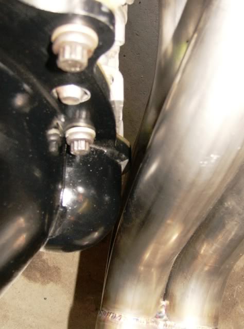
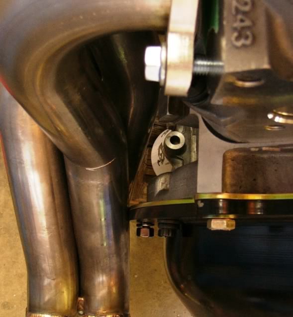
Also, got the headers, starter and all engine wiring installed. Used some stock GM header gaskets with Stage 5 locking header bolts. I hate header leaks so hopefully that should keep things sealed up tight.
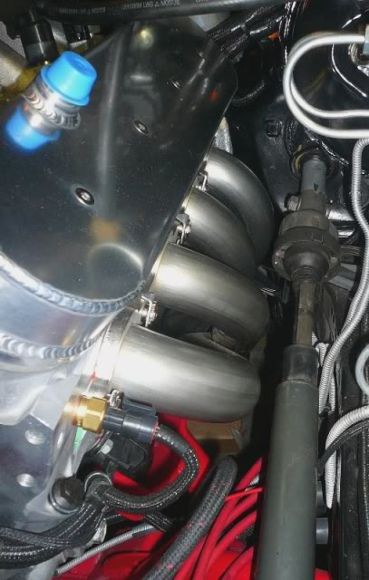
The HO2 sensors went in without too much excitement, only a few small taps to get sufficient clearance on the passenger side, (white paint mark was the target) with the driver side having plenty of room.
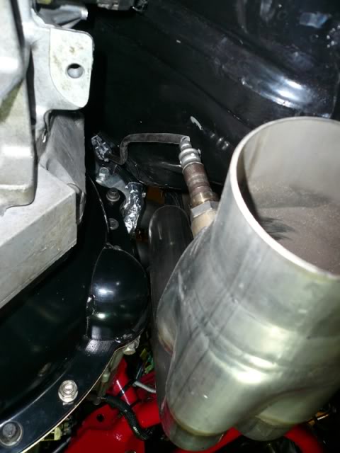
The T56 is just sitting in place until I get the driveshaft setup and aligned. Going to install a front driveshaft loop, just in case my stock LS1 aluminum driveshaft decides to take a walk about.
The HO2 sensors went in without too much excitement, only a few small taps to get sufficient clearance on the passenger side, (white paint mark was the target) with the driver side having plenty of room.
The T56 is just sitting in place until I get the driveshaft setup and aligned. Going to install a front driveshaft loop, just in case my stock LS1 aluminum driveshaft decides to take a walk about.
10-16-2011, 10:57 PM
#59
Re: LS1/6 build and swap .. so long SBC
With the engine installed now, I am working from the driver side to the passenger side cleaning up all the remaining wiring for my nitrous setup.
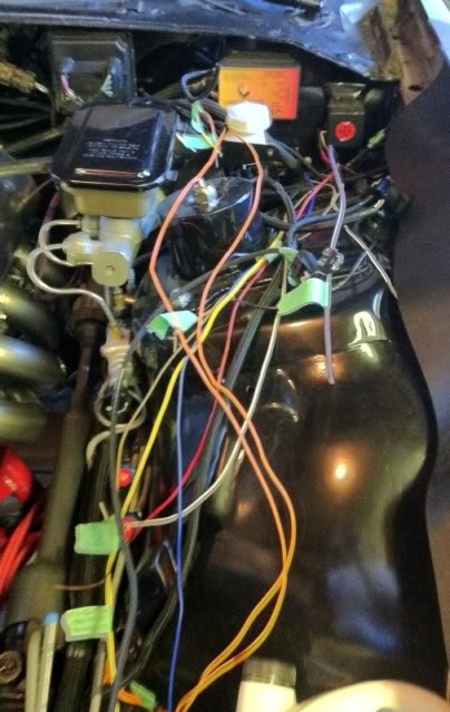
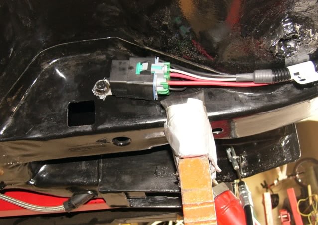
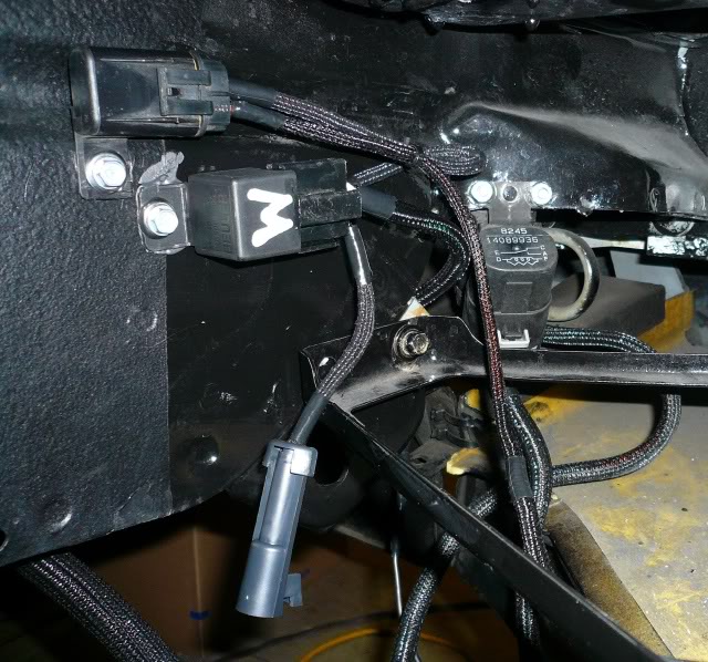
Got working on the nitrous wiring over the weekend to get everything tied together. Here is all the spaghetti that needed to be connected. Hard to believe this is only nitrous control wiring!
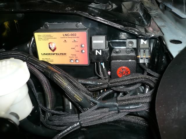
There was enough room above C100 to get all the N2O controls mounted. From right to left, solenoid power fuse, (solenoid power to the switched contact of N2O relay) throttle position switch, N2O / Fuel solenoids relay and my timing/RPM controller.
The timing control will give me a rev limiter and is tied in with my line lock. Not sure if this is the best use of the limiter but is how I had it in my old setup which worked well. In my old setup, my MSD Digital 6 gave me two rev limiters where this one only provides one, so I will be relying on the PCM for max. rev limiting. The ignition retard control signal is coming off the power to the nitrous/fuel solenoids.
The throttle position switch is in series with an N2O enable switch in the console and then to the shifter pushbutton inside the cab and finally onto controlling the solenoids relay.
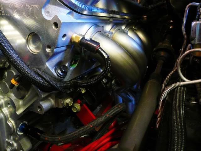
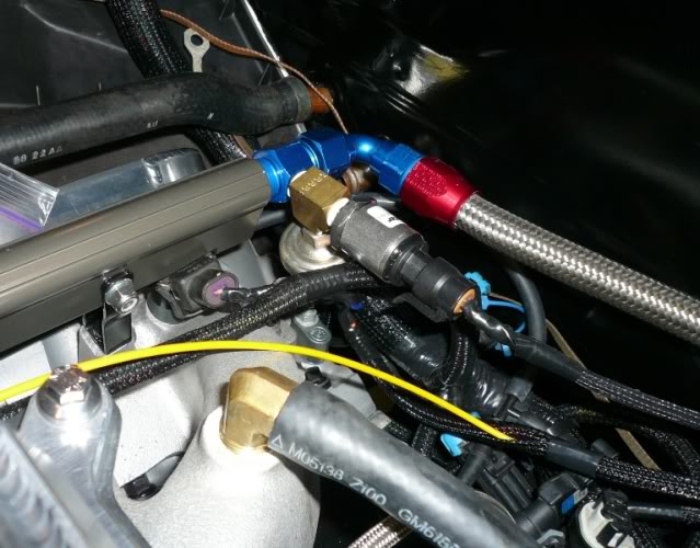
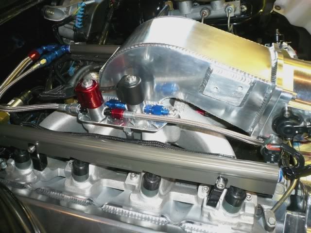
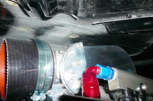
Also tied in a fuel pressure switch (off the bottom of the brass T) into the fuel rail crossover for engine protection should I loose fuel pressure. The switch is tied into the ground circuit of the N2O relay. The sensor is for the remote fuel pressure gauge with the Yellow waiting to be hooked up to the solenoids.
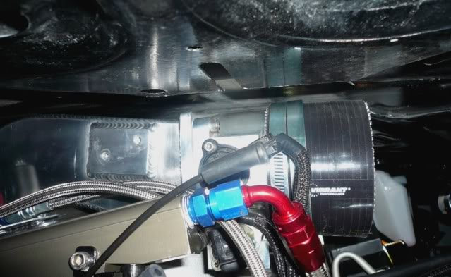
Found some aluminum checker plate in my stash and built a custom bracket for mounting my solenoids. A little of the red neck in me coming out � The solenoids (Edelbrock Performer) were from my previous build, which are only good for up to a 125 HP shot, which should be plenty until I get the rear replaced with something stronger. Installed a 2 pole quick connector so they will be easy to upgrade in the future.
I am feeding the fuel solenoid from the rear of the driver side rail for lack of better connection point. Just need to tie in the nitrous lines yet and this part of the build should be complete.
Got working on the nitrous wiring over the weekend to get everything tied together. Here is all the spaghetti that needed to be connected. Hard to believe this is only nitrous control wiring!
There was enough room above C100 to get all the N2O controls mounted. From right to left, solenoid power fuse, (solenoid power to the switched contact of N2O relay) throttle position switch, N2O / Fuel solenoids relay and my timing/RPM controller.
The timing control will give me a rev limiter and is tied in with my line lock. Not sure if this is the best use of the limiter but is how I had it in my old setup which worked well. In my old setup, my MSD Digital 6 gave me two rev limiters where this one only provides one, so I will be relying on the PCM for max. rev limiting. The ignition retard control signal is coming off the power to the nitrous/fuel solenoids.
The throttle position switch is in series with an N2O enable switch in the console and then to the shifter pushbutton inside the cab and finally onto controlling the solenoids relay.
Also tied in a fuel pressure switch (off the bottom of the brass T) into the fuel rail crossover for engine protection should I loose fuel pressure. The switch is tied into the ground circuit of the N2O relay. The sensor is for the remote fuel pressure gauge with the Yellow waiting to be hooked up to the solenoids.
Found some aluminum checker plate in my stash and built a custom bracket for mounting my solenoids. A little of the red neck in me coming out � The solenoids (Edelbrock Performer) were from my previous build, which are only good for up to a 125 HP shot, which should be plenty until I get the rear replaced with something stronger. Installed a 2 pole quick connector so they will be easy to upgrade in the future.
I am feeding the fuel solenoid from the rear of the driver side rail for lack of better connection point. Just need to tie in the nitrous lines yet and this part of the build should be complete.
10-17-2011, 07:20 AM
#60
Supreme Member

iTrader: (1)
Join Date: Mar 2007
Location: Apopka, Florida
Posts: 1,237
Likes: 0
Received 7 Likes
on
6 Posts
Car: 1989 Pontiac Trans Am GTA
Engine: cammed LS1
Transmission: Monster SS 4L65E
Axle/Gears: 9 bolt posi w/ 3.70 gears
Re: LS1/6 build and swap .. so long SBC
Looks great. Coming along real nicely!
10-20-2011, 01:23 AM
#61
Supreme Member
iTrader: (35)
Join Date: Aug 2006
Location: Mississauga,Ont,Canada
Posts: 1,470
Likes: 0
Received 1 Like
on
1 Post
Car: 89 IROC
Engine: LSX 6.0 370, TU2 Cam, Fast intake
Transmission: T56 w/ lots of goodies
Axle/Gears: 8.8, Posi, 4.10, 31 Spline
Re: LS1/6 build and swap .. so long SBC
Wow awsome build man look forward to seeing it when its done
10-21-2011, 08:11 AM
#63
Senior Member
Re: LS1/6 build and swap .. so long SBC
car is looking great!...the snow part worries me, i hope to be finished before the end of the year, but with the snow, i'll be stuck moving it back and forth in the garage bay! 
Last edited by STREETDEMON; 11-30-2011 at 07:26 PM.
10-22-2011, 12:00 PM
#64
Re: LS1/6 build and swap .. so long SBC
I hear you man. When I was putting the 406 in I completed the build in the middle of winter too. Going through withdrawls I couldn't handle it any longer ...
For our warm southern friends, that is snow on the right hand side of the driveway.
For our warm southern friends, that is snow on the right hand side of the driveway.
10-22-2011, 12:28 PM
#65
Supreme Member
iTrader: (1)
Join Date: Mar 2007
Location: Apopka, Florida
Posts: 1,237
Likes: 0
Received 7 Likes
on
6 Posts
Car: 1989 Pontiac Trans Am GTA
Engine: cammed LS1
Transmission: Monster SS 4L65E
Axle/Gears: 9 bolt posi w/ 3.70 gears
Re: LS1/6 build and swap .. so long SBC
Sounds good man! Glad I live in Florida 
 10-31-2011, 07:39 PM
#67
Re: LS1/6 build and swap .. so long SBC
I am building this primarily as a street car so I never worried about it. I wanted the QT bell because I like my feet....piece of mind over the stock thin walled aluminum piece should something come apart on a clutch dump.
Not planning a cage either so if I can run mid to high 11s I will be quite happy for now. If I decide to go faster in the future, it will need recertification within a couple years anyway. At that time I could send it to QT to verify the modification and hopefully get certification at that time.
For those looking to go faster, definetly check into the applicable regulations to ensure you will pass inspection. Here is a brief excerpt from the NHRA Regulations.
NHRA General Regulations:
2:10 FLYWHEEL SHIELD: Other Classes
"All other cars using a clutch and running 11.49 or quicker must be
equipped with an SFI 6.1, 6.2, 6.3, or 9.1 flywheel shield. See
Section 2:6 for motor plate and general requirements. There shall be
a minimum of seven 3/8-inch-diameter Grade 8 bolts or high strength
steel studs in the top half of the bellhousing. There shall be a
minimum of eight 3/8-inch-diameter Grade 8 bolts or high strength
steel studs in the bottom half of the bellhousing used to fasten the
bellhousing to the motor plate. Modifications or repairs to the flywheel
shield prohibited except if performed and recertified by manufacturer."equipped with an SFI 6.1, 6.2, 6.3, or 9.1 flywheel shield. See
Section 2:6 for motor plate and general requirements. There shall be
a minimum of seven 3/8-inch-diameter Grade 8 bolts or high strength
steel studs in the top half of the bellhousing. There shall be a
minimum of eight 3/8-inch-diameter Grade 8 bolts or high strength
steel studs in the bottom half of the bellhousing used to fasten the
bellhousing to the motor plate. Modifications or repairs to the flywheel
10-31-2011, 08:25 PM
#68
Re: LS1/6 build and swap .. so long SBC
Got a few more things put together over the weekend. Pulled out my Ebay radiator to see how I would be able to tie in the steam hose and was quite happy to find the upper port that was previously used for the heater core return hose for the SBC, was also threaded for 1/8" NPT.
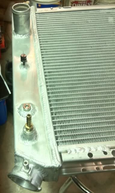
The rad is a Champion 3 row that I bought for under $200. Rad itself is built quite well for the price and came with a free rad cap. The cap was only worth what you pay for it ... after I took it off with some pliers it was filed.
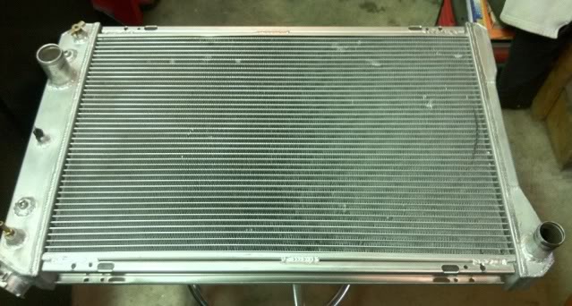
Reused my upper and lower flexible hoses.
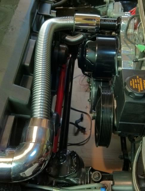
Once I go both hoses on I was happy to have that job done. On second look I thought, man is that lower hose setup butt ugly. That might have to change...
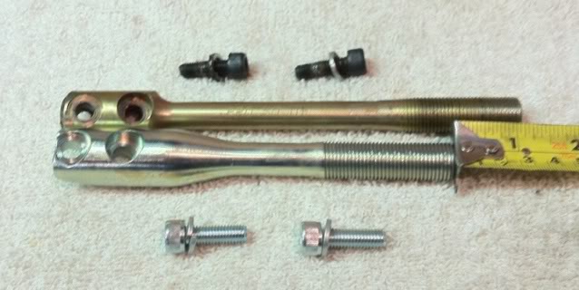
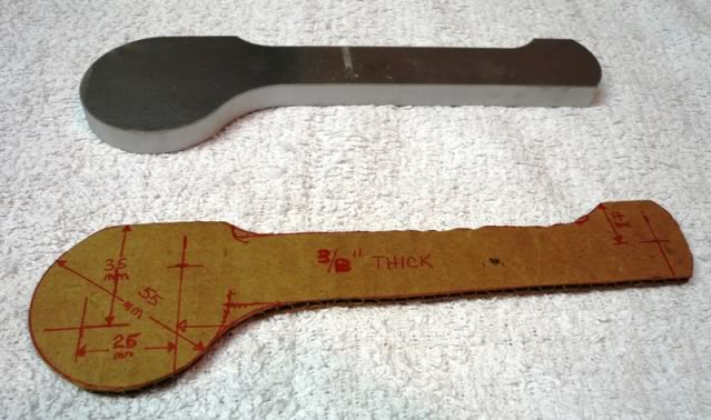
Got the tranny filled with fluid and then changed out the shifter shaft. My tranny came with Pro 5.0 shifter and I was running it with a UMI shifter handle, but the combination of the two made for a very long throw. Replaced the Pro 5.0 shifter handle with a UMI short shifter which is just over an inch shorter.
Here is a comparisson of the two.
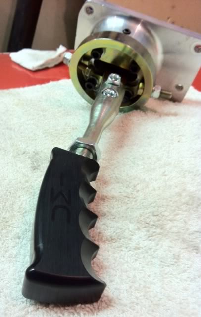
And the full shifter setup. I really like the solid feel of this handle and it doesn't move at all once setup in position.
The rad is a Champion 3 row that I bought for under $200. Rad itself is built quite well for the price and came with a free rad cap. The cap was only worth what you pay for it ... after I took it off with some pliers it was filed.
Reused my upper and lower flexible hoses.
Once I go both hoses on I was happy to have that job done. On second look I thought, man is that lower hose setup butt ugly. That might have to change...
Got the tranny filled with fluid and then changed out the shifter shaft. My tranny came with Pro 5.0 shifter and I was running it with a UMI shifter handle, but the combination of the two made for a very long throw. Replaced the Pro 5.0 shifter handle with a UMI short shifter which is just over an inch shorter.
Here is a comparisson of the two.
And the full shifter setup. I really like the solid feel of this handle and it doesn't move at all once setup in position.
11-14-2011, 11:16 PM
#69
Re: LS1/6 build and swap .. so long SBC
Had some more progress putting my fuel system together ... one more step closer. I had previously installed my fuel pump, upgrading it to a Walbro GSS340M 255L/hr in tank fuel pump, so only had the wiring to complete. With relocating the battery to the rear, I installed the fuel pump relay just in front of the passenger side control arm mount. Cleaned up the mounting point to double as my fuel pump relay ground connection. With mounting it close to that frame pocket I was able to install a nut on the rear to provide a real solid ground.
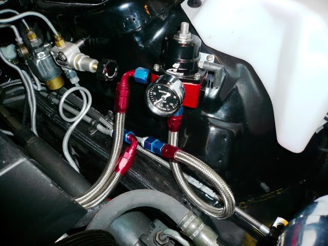
I am reusing the stock fuel filter location and hardlines to the engine bay where I installed a Aeromotive 13101 regulator. From the fuel supply hardline I ran a -6 AN line direct to the driver side fuel rail, through the -8 AN crossover in the rear and returning from the passenger side fuel rail with -6 AN to the inlet port of the regulator, using it to provide back pressure control on the fuel rails. From the reg another -6 AN line connects the bottom return port to the return hardline.
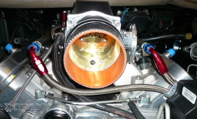
With hoping to have this intake fit under the stock hood I needed to rotate my throttle body 180 degrees to provide some additional clearance as there was no way it was going to fit with the throttle body right side up. Then had to extend the wiring to get it all tied back together. This should create some difficulty in hooking up a throttle cable, but will see what I can come up with.
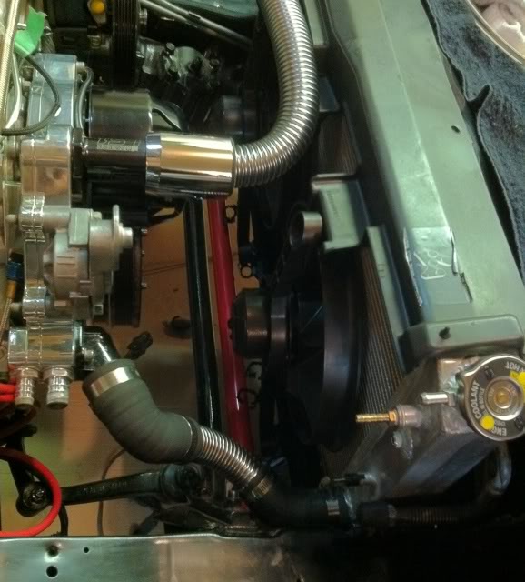
Moving on, I completed the wiring for my electric water pump, running the wiring to the relay and fuse which I located within the passenger side front fender. I routed this along the steam line to the rad and then ran it with the fan wiring to the relays.
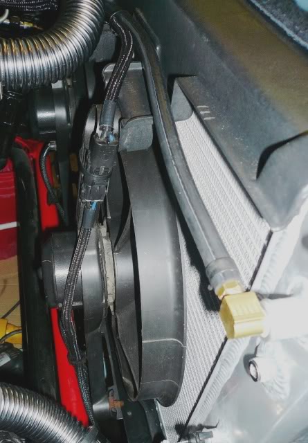
Also relocated the stock Lo/Hi speed fan relays, mounting them back to back just behind the passenger side bumper mounts so they will be protected from road damage. I have been installing quick connections where needed to keep the wiring modular to ease future removal.
Power distribution wiring interconnection up next ...
I am reusing the stock fuel filter location and hardlines to the engine bay where I installed a Aeromotive 13101 regulator. From the fuel supply hardline I ran a -6 AN line direct to the driver side fuel rail, through the -8 AN crossover in the rear and returning from the passenger side fuel rail with -6 AN to the inlet port of the regulator, using it to provide back pressure control on the fuel rails. From the reg another -6 AN line connects the bottom return port to the return hardline.
With hoping to have this intake fit under the stock hood I needed to rotate my throttle body 180 degrees to provide some additional clearance as there was no way it was going to fit with the throttle body right side up. Then had to extend the wiring to get it all tied back together. This should create some difficulty in hooking up a throttle cable, but will see what I can come up with.
Moving on, I completed the wiring for my electric water pump, running the wiring to the relay and fuse which I located within the passenger side front fender. I routed this along the steam line to the rad and then ran it with the fan wiring to the relays.
Also relocated the stock Lo/Hi speed fan relays, mounting them back to back just behind the passenger side bumper mounts so they will be protected from road damage. I have been installing quick connections where needed to keep the wiring modular to ease future removal.
Power distribution wiring interconnection up next ...
11-15-2011, 12:34 AM
#70
Member

Join Date: May 2011
Location: Andalusia, AL
Posts: 286
Likes: 0
Received 0 Likes
on
0 Posts
Car: 1991 Camaro RS
Axle/Gears: Stock
Re: LS1/6 build and swap .. so long SBC
i like the wire looming you used, where did you get it from? great conversion! looking forward to updates
11-15-2011, 09:52 AM
#71
Member
Join Date: Dec 2010
Location: ohio
Posts: 296
Likes: 0
Received 0 Likes
on
0 Posts
Car: OVRMYHD
Engine: H/C/I LS1
Transmission: 4L60E 3,200 Edge stall
Axle/Gears: 9 bolt w/3.90
Re: LS1/6 build and swap .. so long SBC
11-15-2011, 08:35 PM
#72
Re: LS1/6 build and swap .. so long SBC
Well local track is not always the best prepped and being at 3500' that will be working against me as well. Once I get her running, it will be time to start saving for a rear end upgrade to replace my built up 4th gen 10 bolt in her now. Then it will be time for the safety upgrades, drag radials and hammer time.
Till then I have 4 good 275s that are in need of some abuse.
1FSTBRD - The looming comes from my local Mopac Auto Supply. It is their in house brand called Performance World. Might be a stretch for you to get ahold of some as they are only located in Western Canada.
http://www.mopacautosupply.com/index.html
11-15-2011, 09:20 PM
#73
Senior Member
iTrader: (5)
Join Date: Dec 2008
Location: Alabama
Posts: 719
Likes: 0
Received 0 Likes
on
0 Posts
Car: 1986 camaro
Engine: ls2
Transmission: FLT stage 6 60e
Axle/Gears: 8.8 with 3.73's
Re: LS1/6 build and swap .. so long SBC
might i ask why you chose a 2 inch primary header over a 1 3/4 for a ls1?
11-15-2011, 10:10 PM
#74
Re: LS1/6 build and swap .. so long SBC
I think the 1 3/4" would have been better choice for this particular motor and my current use, but purchasing the headers from Canada makes them pretty costly. So, I went for the long term purchase and went with the 2" primaries with 3" collectors to hook up to my Mufflex exhaust, with the expectation of either S/C or bigger cubic inches in the future.
My buddy I bought the engine from also swore by the 2" primaries he was running on it at the time. He was primarily drag racing his 2001 TA with the bolt ons you see here and a 200 shot of N2O, running 10.60s once he went automatic. He researched it to death and from my own research, it also led me to believe 1 3/4" are holding back a little power on the top end, though they make up for it on the bottom. Mine is not a daily driver neither, more of a stress reliever, so when I do drive it I seem to like the loud pedal.
Also, I was buying when Hawks had them on sale for the same price as the 1 3/4".
11-15-2011, 10:24 PM
#75
Senior Member
iTrader: (5)
Join Date: Dec 2008
Location: Alabama
Posts: 719
Likes: 0
Received 0 Likes
on
0 Posts
Car: 1986 camaro
Engine: ls2
Transmission: FLT stage 6 60e
Axle/Gears: 8.8 with 3.73's
Re: LS1/6 build and swap .. so long SBC
I think the 1 3/4" would have been better choice for this particular motor and my current use, but purchasing the headers from Canada makes them pretty costly. So, I went for the long term purchase and went with the 2" primaries with 3" collectors to hook up to my Mufflex exhaust, with the expectation of either S/C or bigger cubic inches in the future.
My buddy I bought the engine from also swore by the 2" primaries he was running on it at the time. He was primarily drag racing his 2001 TA with the bolt ons you see here and a 200 shot of N2O, running 10.60s once he went automatic. He researched it to death and from my own research, it also led me to believe 1 3/4" are holding back a little power on the top end, though they make up for it on the bottom. Mine is not a daily driver neither, more of a stress reliever, so when I do drive it I seem to like the loud pedal.
Also, I was buying when Hawks had them on sale for the same price as the 1 3/4".
My buddy I bought the engine from also swore by the 2" primaries he was running on it at the time. He was primarily drag racing his 2001 TA with the bolt ons you see here and a 200 shot of N2O, running 10.60s once he went automatic. He researched it to death and from my own research, it also led me to believe 1 3/4" are holding back a little power on the top end, though they make up for it on the bottom. Mine is not a daily driver neither, more of a stress reliever, so when I do drive it I seem to like the loud pedal.
Also, I was buying when Hawks had them on sale for the same price as the 1 3/4".
 11-17-2011, 01:05 PM
#76
Member
Join Date: Dec 2010
Location: ohio
Posts: 296
Likes: 0
Received 0 Likes
on
0 Posts
Car: OVRMYHD
Engine: H/C/I LS1
Transmission: 4L60E 3,200 Edge stall
Axle/Gears: 9 bolt w/3.90
Re: LS1/6 build and swap .. so long SBC
Better to have to much header than too little
11-17-2011, 09:11 PM
#78
Member
Join Date: Dec 2010
Location: ohio
Posts: 296
Likes: 0
Received 0 Likes
on
0 Posts
Car: OVRMYHD
Engine: H/C/I LS1
Transmission: 4L60E 3,200 Edge stall
Axle/Gears: 9 bolt w/3.90
11-22-2011, 10:43 PM
#79
Re: LS1/6 build and swap .. so long SBC
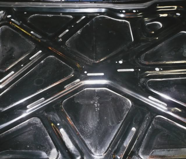
Pulled down the hood from its storage location on my garage roof and did a quick test fit to see if I am going to have to spend more bones on a new hood. I really want to keep this looking stock as I like the stock TransAm hood with the front and rear vents, which I also plan to make functional as well. Placed the stock hood on with the hood insulation and without it fully seated noticed the insulation was touching the intake right at the intake hose coupling. Hmmm, lets get out the dremel 
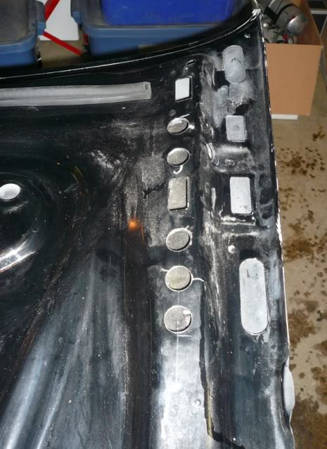
Here is the underside of the hood before any modifications.
Removal of the insulation itself was good for about a 1/2" of additional clearance and here is what I am looking to gain with the support removal.
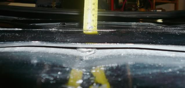
I marked up an 8" slot down the center for removal and brought out the dremel. I thought it might be a little light for the job, but it worked perfect. The finished cut. Looks like it is crooked in the picture but is actually squarely cut.
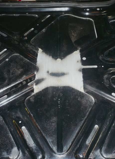
Installed the hood and gingerly click here down ... nothing touched that I could notice so I slithered the camera up from the bottom to get some pics of how things were sitting.
She's a fit, with some additional room for engine movement. How much, I am not sure as it was tough enough just to get a pic.
While I was in the hood cutting mood, I brought out the 1/2" hole saw and added a number of additional vent holes to add some functionality to the stock vents. Removed the front vents and left the rears in position for the modification. This should help keep the underhood temperature down a little.
The three front holes will have air aimed into the top of the radiator with the back two flowing clear into the engine bay.
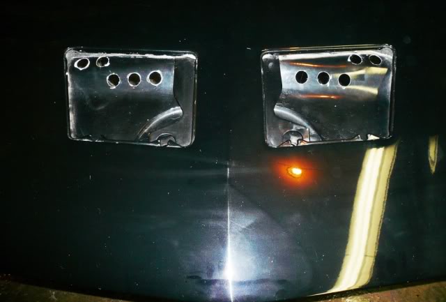
Additional holes also added at rear vents to help the air flow through.
Now some clean up and a fresh coat under hood to come.
Sorry for the crappy pics. My camera and I aren't getting along well lately.
Here is the underside of the hood before any modifications.
Removal of the insulation itself was good for about a 1/2" of additional clearance and here is what I am looking to gain with the support removal.
I marked up an 8" slot down the center for removal and brought out the dremel. I thought it might be a little light for the job, but it worked perfect. The finished cut. Looks like it is crooked in the picture but is actually squarely cut.
Installed the hood and gingerly click here down ... nothing touched that I could notice so I slithered the camera up from the bottom to get some pics of how things were sitting.
She's a fit, with some additional room for engine movement. How much, I am not sure as it was tough enough just to get a pic.
While I was in the hood cutting mood, I brought out the 1/2" hole saw and added a number of additional vent holes to add some functionality to the stock vents. Removed the front vents and left the rears in position for the modification. This should help keep the underhood temperature down a little.
The three front holes will have air aimed into the top of the radiator with the back two flowing clear into the engine bay.
Additional holes also added at rear vents to help the air flow through.
Now some clean up and a fresh coat under hood to come.
Sorry for the crappy pics. My camera and I aren't getting along well lately.
11-27-2011, 06:10 PM
#80
Re: LS1/6 build and swap .. so long SBC
Watching a few of you southern brothers working on your cars and engines in the driveway is making me jealous. With our weather holding (no snow at the moment) I am pushing to get this thing started, hoping that if I get things together and another chinook blows through I can get a run in before next summer.
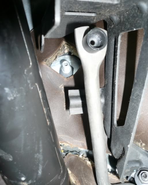
Got to work on the clutch, thinking I would slip the actuation rod of my Tick clutch master cylinder onto the stock 3rd gen clutch pedal to bleed the system only to find it is not a direct fit with the 3rd gen pedal. As the master cylinder is for the 4th gen, LS1 T56 the bore size at the clutch pedal is different. The stock 3rd gen clutch pedal has a 0.428" post for the master cylinder to attach to with the Tick master cylinder rod end bore only 0.375". Out came the Dremel again .... I don't know how a guy could live without one of these things! Enlarged the bore to fit, cleaned it up and slipped her onto the pedal post.
Not sure what others are using to hold the rod end on the pedal post as it is too wide to install any retaining clip on the outside, so I straped a tie-wrap around the rod end and the pedal to keep it in place. With the clutch load being on the post itself I don't think this will be a problem, but wouldn't mind knowing what others have done.
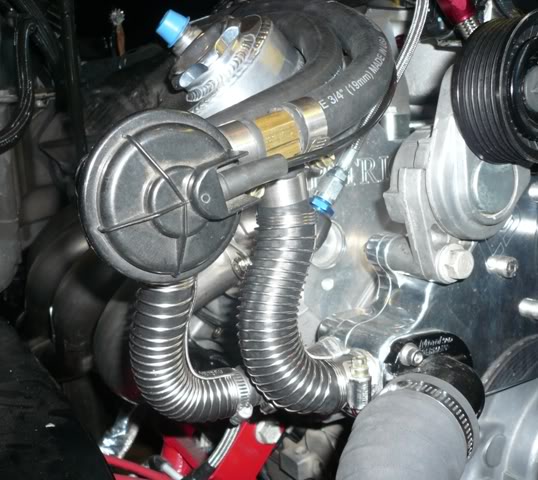
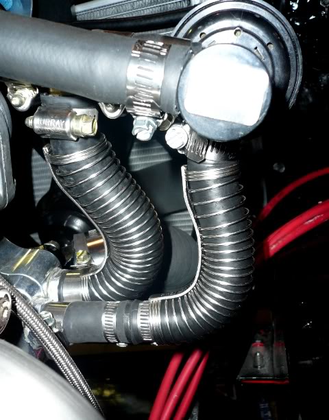
Then moved onto finishing off the cooling system, with now only having the the heater core hoses left to install. I wanted to keep the TPI heater core bypass valve in place to keep the car interior cooler in the summer time. (Yes, we do get some hot days here!)
When I picked up this engine, I grabbed all the heater core hoses (4th gen) as well which had two sizes of the S shaped elbow, same as the heater core return hose on the TPI setup. These actually worked out quite well with installing them at the water pump end. I extended the water pump outlet elbow by 2" to add some length for it to crossover to the connection point on the control valve and used the inlet elbow as it was, installing a T right above the control valve for coolant return when the heater core is being bypassed.
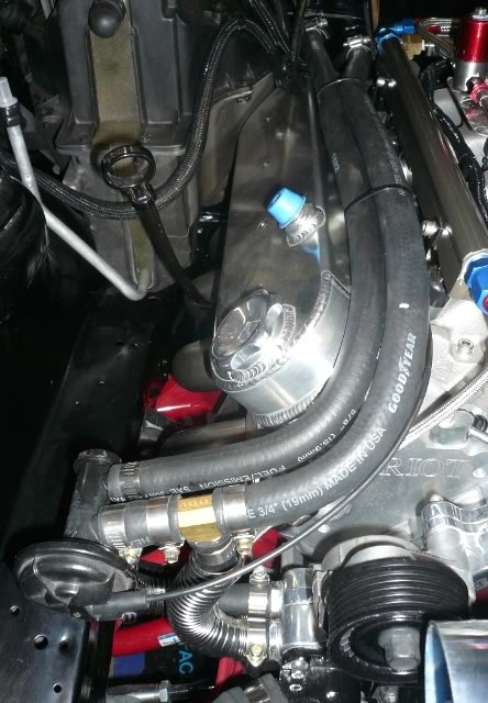
Also got started on my CAI which I am going to run to the passenger side and through the tray. I picked up some Vibrant 4" aluminum pieces to get started. In mocking up the intake, I decided to change out the stock radiator overflow tank with a Canton aluminum version, so I am waiting for that to arrive before the CAI is completed.
Been shopping around for some NGK plugs for this setup with 100 shot of nitrous in mind for now and have had some difficulty finding anything but the stock heat range here in Canada. Im my searching, I stumbled onto the clubplug.ca and order up some NGK R5724-8 race plugs.
While I am waiting for the plugs to arrive, I will get my valve cover breather setup installed and hopefully be ready for a start soon.
Got to work on the clutch, thinking I would slip the actuation rod of my Tick clutch master cylinder onto the stock 3rd gen clutch pedal to bleed the system only to find it is not a direct fit with the 3rd gen pedal. As the master cylinder is for the 4th gen, LS1 T56 the bore size at the clutch pedal is different. The stock 3rd gen clutch pedal has a 0.428" post for the master cylinder to attach to with the Tick master cylinder rod end bore only 0.375". Out came the Dremel again .... I don't know how a guy could live without one of these things! Enlarged the bore to fit, cleaned it up and slipped her onto the pedal post.
Not sure what others are using to hold the rod end on the pedal post as it is too wide to install any retaining clip on the outside, so I straped a tie-wrap around the rod end and the pedal to keep it in place. With the clutch load being on the post itself I don't think this will be a problem, but wouldn't mind knowing what others have done.
Then moved onto finishing off the cooling system, with now only having the the heater core hoses left to install. I wanted to keep the TPI heater core bypass valve in place to keep the car interior cooler in the summer time. (Yes, we do get some hot days here!)
When I picked up this engine, I grabbed all the heater core hoses (4th gen) as well which had two sizes of the S shaped elbow, same as the heater core return hose on the TPI setup. These actually worked out quite well with installing them at the water pump end. I extended the water pump outlet elbow by 2" to add some length for it to crossover to the connection point on the control valve and used the inlet elbow as it was, installing a T right above the control valve for coolant return when the heater core is being bypassed.
Also got started on my CAI which I am going to run to the passenger side and through the tray. I picked up some Vibrant 4" aluminum pieces to get started. In mocking up the intake, I decided to change out the stock radiator overflow tank with a Canton aluminum version, so I am waiting for that to arrive before the CAI is completed.
Been shopping around for some NGK plugs for this setup with 100 shot of nitrous in mind for now and have had some difficulty finding anything but the stock heat range here in Canada. Im my searching, I stumbled onto the clubplug.ca and order up some NGK R5724-8 race plugs.
While I am waiting for the plugs to arrive, I will get my valve cover breather setup installed and hopefully be ready for a start soon.
Last edited by HP52TA; 12-15-2011 at 10:52 PM. Reason: Changed plug numbers - NGK recommendation was wrong plugs
11-28-2011, 08:30 AM
#81
Senior Member
Re: LS1/6 build and swap .. so long SBC
its coming together nice! i have to admit, i didn't even touch mine over the holiday weekend. for the 3rd gen clutch pedal, i drilled out the post that was in the pedal and added a 3/8" hitch pin. bluezee(nick) has a post on here about the modification. i may have to borrow your idea for routing the heater core hoses, that looks really clean. we had heavy frost today in my area, it was sub 20*, so i know how you feel!
11-28-2011, 08:46 AM
#82
Supreme Member
iTrader: (1)
Join Date: Mar 2007
Location: Apopka, Florida
Posts: 1,237
Likes: 0
Received 7 Likes
on
6 Posts
Car: 1989 Pontiac Trans Am GTA
Engine: cammed LS1
Transmission: Monster SS 4L65E
Axle/Gears: 9 bolt posi w/ 3.70 gears
Re: LS1/6 build and swap .. so long SBC
Thanks for the pics of how you did your heater core hoses HP. That gives me an idea for mine. 
11-28-2011, 10:50 PM
#83
Re: LS1/6 build and swap .. so long SBC
I was running a 4th gen master previously with only the ty-wrap keeping it on the post without issue. Seems a little geto though, so might have to do the drill mod.
Post up pics when you get it sorted out.
11-29-2011, 09:38 AM
#84
Junior Member

Join Date: May 2011
Location: Fort Myers, FL
Posts: 10
Likes: 0
Received 0 Likes
on
0 Posts
 11-29-2011, 08:51 PM
#85
Re: LS1/6 build and swap .. so long SBC
Nothing real special on the fittings. Used a 1/8" NPT male to 1/8" NPT Female 90 degree fitting with a 1/8" NPT to barbed fitting for the hose connection. Before you head to the store, find the correct size hose for the crossover tube connection and take it with you to pickup the right sized barb fitting.
Not sure what rad you have, but mine was already tapped for the 1/8" NPT where the fitting is screwed into. I would confirm that connection first, before purchasing any other fittings.
Not sure what rad you have, but mine was already tapped for the 1/8" NPT where the fitting is screwed into. I would confirm that connection first, before purchasing any other fittings.
11-30-2011, 02:07 PM
#86

Re: LS1/6 build and swap .. so long SBC
1FSTBRD - The looming comes from my local Mopac Auto Supply. It is their in house brand called Performance World. Might be a stretch for you to get ahold of some as they are only located in Western Canada.
http://www.mopacautosupply.com/index.html
http://www.mopacautosupply.com/index.html
12-02-2011, 06:18 PM
#87
Junior Member
Join Date: May 2011
Location: Fort Myers, FL
Posts: 10
Likes: 0
Received 0 Likes
on
0 Posts
Re: LS1/6 build and swap .. so long SBC
I have a stock rad with plastic tanks. Looking to try to utilize the heater hose return port for the steam line...
back to the drawing board!
12-19-2011, 10:00 PM
#88
Re: LS1/6 build and swap .. so long SBC
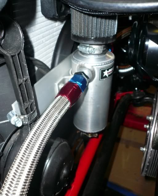
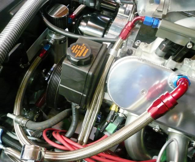
Been finishing off a few things over the last couple weeks, in hopes of getting this thing up and running over the xmas break. My Canton coolant reservoir showed up, so I pieced together my air intake. I am running a speed density tune, so no MAF inline, just the IAT under the elbow.
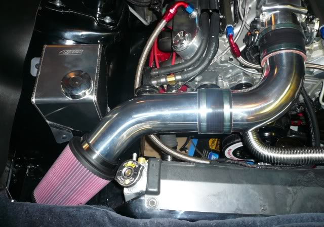
I was going to run the intake through the passenger side tray to have a true CAI intake, but decided to hold off for now. Going to save that cut for something better down the road.
Built up a quick and dirty bracket out of some aluminum plate to support the valve cover breather tubes catch can. Just cut some grooves in the plate to run through some clamps and tightened up to the fan supports.
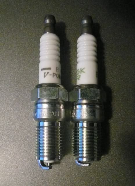
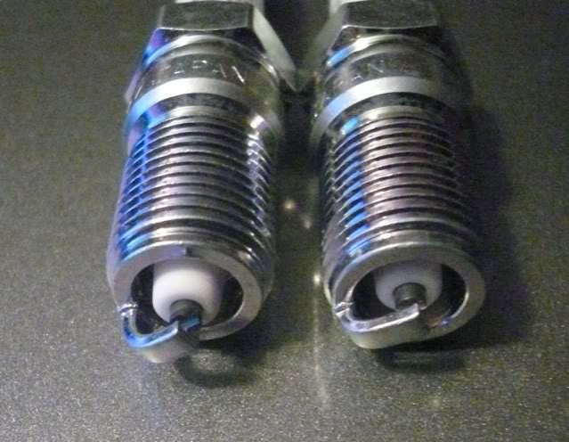
My plugs showed up but, with gaskets ... NGK tech support spec'd me the wrong plug from there race series plugs and I failed to check the plug dimensions before ordering. The plug was for a SBC. Luckily the boys at clubplug helped me get the correct plugs and let me return my first failed attempt. They found me the right race series plug I was looking for but upon opening the box ... found they are a projected nose plug. Was expecting the plug nose to be as per the NGK site pic.

I order two types of plugs, BR7EF for zero to small shot of nitrous and some R5724-8 race series for upping the nitrous pills. The R5724-8 is on the left with the projected nose. I am thinking of exchanging them for another set of the BR7EFs on the right. Any thoughts? Not planning more than a 125 shot.
I was going to run the intake through the passenger side tray to have a true CAI intake, but decided to hold off for now. Going to save that cut for something better down the road.
Built up a quick and dirty bracket out of some aluminum plate to support the valve cover breather tubes catch can. Just cut some grooves in the plate to run through some clamps and tightened up to the fan supports.
My plugs showed up but, with gaskets ...
NGK tech support spec'd me the wrong plug from there race series plugs and I failed to check the plug dimensions before ordering. The plug was for a SBC. Luckily the boys at clubplug helped me get the correct plugs and let me return my first failed attempt. They found me the right race series plug I was looking for but upon opening the box ... found they are a projected nose plug. Was expecting the plug nose to be as per the NGK site pic. I order two types of plugs, BR7EF for zero to small shot of nitrous and some R5724-8 race series for upping the nitrous pills. The R5724-8 is on the left with the projected nose. I am thinking of exchanging them for another set of the BR7EFs on the right. Any thoughts? Not planning more than a 125 shot.
12-28-2011, 11:40 PM
#89
Re: LS1/6 build and swap .. so long SBC
Got my plugs concerns all sorted out by doing a little more research. Found two good references:
http://www.ls1.com/forums/f10/spark-...e-chart-13070/
http://ls1tech.com/forums/8499298-post7.html
With flipping my throttle body 180 degrees to provide additional hood clerance, I have been trying to find a bracket for quite sometime without any luck, so I decided to build up a custom bracket to mount off the manifold. After a bunch of measurements and a few different cardboard designs, here is what I finally ending up with. For now I am only hooking up the throttle, but will be adding the 4th Gen cruise unit cable down the road.
Took the template to my favorite sign cutting fabrication shop to have them cut this template out of some 3/8" aluminum plate. They can cut some pretty amazing shapes with thin metals, but I wasn't sure if they could cut this kind of thickness. Here is the rough cut piece, which you can see a slight grain where the cut was made.
And the final product after drilling the holes and a little sanding / polishing. Turned out to be a real solid piece.

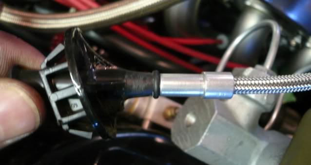
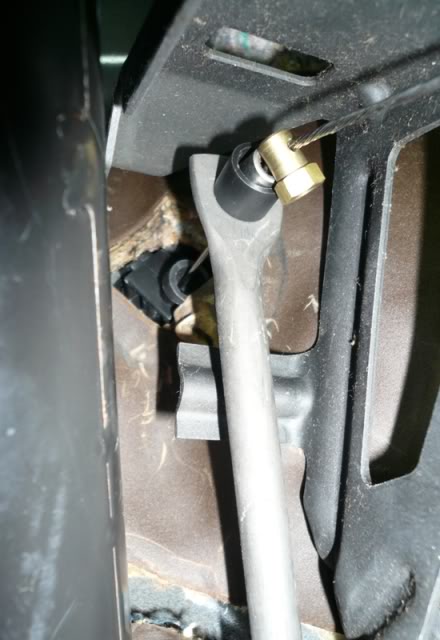
Installed the Lokar LS1 cable to the pedal next, with using fender washers on the Lokar adjuster where it goes through the body. When operating the pedal I could hear the cable scraping across the outlet of the Lokar adjuster. It worked but I think after lots of use it may fray and break the inner cable ... likely at the most inopportune time. Here you can see how the cable and pedal is mis-aligned.
Looking for a smoother operating solution, I went back to the stock TPI cable to see what angle it was using for entry into the cab. As you can see, the cable goes through the firewall connector at quite an angle.
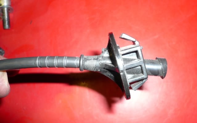
Even though the cable housing looked to be one piece I attempted to seperate the cable from the firewall connector. First I cut the housing off about three inches from the firewall connector, then scored the outer plastic housing, then put the housing in the vise and clamped her down tight. With a little work and pulling the inner housing pulled out of the firewall connector.
Max pics - post continued.
http://www.ls1.com/forums/f10/spark-...e-chart-13070/
http://ls1tech.com/forums/8499298-post7.html
With flipping my throttle body 180 degrees to provide additional hood clerance, I have been trying to find a bracket for quite sometime without any luck, so I decided to build up a custom bracket to mount off the manifold. After a bunch of measurements and a few different cardboard designs, here is what I finally ending up with. For now I am only hooking up the throttle, but will be adding the 4th Gen cruise unit cable down the road.
Took the template to my favorite sign cutting fabrication shop to have them cut this template out of some 3/8" aluminum plate. They can cut some pretty amazing shapes with thin metals, but I wasn't sure if they could cut this kind of thickness. Here is the rough cut piece, which you can see a slight grain where the cut was made.
And the final product after drilling the holes and a little sanding / polishing. Turned out to be a real solid piece.
Installed the Lokar LS1 cable to the pedal next, with using fender washers on the Lokar adjuster where it goes through the body. When operating the pedal I could hear the cable scraping across the outlet of the Lokar adjuster. It worked but I think after lots of use it may fray and break the inner cable ... likely at the most inopportune time. Here you can see how the cable and pedal is mis-aligned.
Looking for a smoother operating solution, I went back to the stock TPI cable to see what angle it was using for entry into the cab. As you can see, the cable goes through the firewall connector at quite an angle.
Even though the cable housing looked to be one piece I attempted to seperate the cable from the firewall connector. First I cut the housing off about three inches from the firewall connector, then scored the outer plastic housing, then put the housing in the vise and clamped her down tight. With a little work and pulling the inner housing pulled out of the firewall connector.
Max pics - post continued.
12-28-2011, 11:44 PM
#90
Re: LS1/6 build and swap .. so long SBC
(Continued from previous post)
Next up was the removal of the remaining outer casing left in the firewall connector which again I clamped down on in the vise and it pulled right out. Here is what I was trying to accomplish, fitting the Lokar cable end into the stock TPI firewall connector.
As the connector end was about the same size as the Lokar cable end, I cut the end of the firewall connector to provide more area, allowing me to drill out the connector large enough to fit the Lokar cable end. I was very careful when drilling this out not to drill through the connector all together. I stepped up every drill bit size and drilled slowly until the hole was just the right size and depth to fit the cable end.
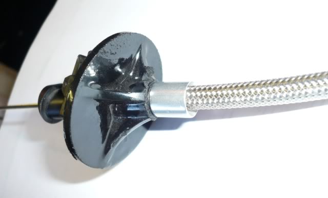
With the cable now entering the cab at the stock angle, it was much smoother and had no drag at all.
Have also been finishing up all the in cab wiring to complete the swap with the battery relocation, as well as all the 4th Gen cruise wiring as per Pockets great write ups. Only have the alternator cable left to add to the + power distribution block and the wiring will be complete.
Also checked to see how different my previous exhaust setup (SBC Hooker 2210s to Mufflex Y) was to fitting hoping for only a few modifications, but looks like it will be a redo between the LS headers to the 4" intermediate pipe. Another ghettocruiser Y-pipe to come. Start up might have to be through open headers ... one more reason for the neighbours to like me.
Next up was the removal of the remaining outer casing left in the firewall connector which again I clamped down on in the vise and it pulled right out. Here is what I was trying to accomplish, fitting the Lokar cable end into the stock TPI firewall connector.
As the connector end was about the same size as the Lokar cable end, I cut the end of the firewall connector to provide more area, allowing me to drill out the connector large enough to fit the Lokar cable end. I was very careful when drilling this out not to drill through the connector all together. I stepped up every drill bit size and drilled slowly until the hole was just the right size and depth to fit the cable end.
With the cable now entering the cab at the stock angle, it was much smoother and had no drag at all.
Have also been finishing up all the in cab wiring to complete the swap with the battery relocation, as well as all the 4th Gen cruise wiring as per Pockets great write ups. Only have the alternator cable left to add to the + power distribution block and the wiring will be complete.
Also checked to see how different my previous exhaust setup (SBC Hooker 2210s to Mufflex Y) was to fitting hoping for only a few modifications, but looks like it will be a redo between the LS headers to the 4" intermediate pipe. Another ghettocruiser Y-pipe to come. Start up might have to be through open headers ... one more reason for the neighbours to like me.
12-29-2011, 12:09 AM
#91
Supreme Member

Re: LS1/6 build and swap .. so long SBC
You did the same thing I did for my throttle cable going through the firewall.The tpi cable grommet made for the perfect angle and smooth operation of the lokar cable and adjusting it for a very snappy throttle response was very easy.very nice work on this build my friend.Hope that cam is ready for the first engine startup vid.Looking forward to hearing her purr with open headers
12-29-2011, 08:01 AM
#92
Supreme Member
iTrader: (1)
Join Date: Mar 2007
Location: Apopka, Florida
Posts: 1,237
Likes: 0
Received 7 Likes
on
6 Posts
Car: 1989 Pontiac Trans Am GTA
Engine: cammed LS1
Transmission: Monster SS 4L65E
Axle/Gears: 9 bolt posi w/ 3.70 gears
Re: LS1/6 build and swap .. so long SBC
Thanks for all of the photos and information on your throttle cable. I've been trying to figure out which way to go for the cable on my swap and now I know. I'm going to do it the same way you did. 
Your swap is coming along great. Keep up the good work!
Your swap is coming along great. Keep up the good work!
12-29-2011, 10:50 PM
#94
Re: LS1/6 build and swap .. so long SBC
86White_T/A305 - I like your thinking, I find it works as good as, if not better than the stock TPI setup. I have always liked a snappy return to the throttle as well and that previous cable drag wasn't cutting it.
Glad to be of help. Just be careful when drilling it out, using slow drill bit speeds. The bit wants to auger into the plastic, so go slow.
Yes, pretty much same. It is a split tube which overlaps itself, wraps the wires about 540 degrees and is available in different diameters. To prevent any fraying at the ends, you need to either heat shrink them or wrap the ends in electrical tape. I choose electrical tape method and after wrapping the loom, cut the tape with scissors to keep a clean square look to the ends.
Yes, pretty much same. It is a split tube which overlaps itself, wraps the wires about 540 degrees and is available in different diameters. To prevent any fraying at the ends, you need to either heat shrink them or wrap the ends in electrical tape. I choose electrical tape method and after wrapping the loom, cut the tape with scissors to keep a clean square look to the ends.
12-30-2011, 08:14 AM
#95
Senior Member
Re: LS1/6 build and swap .. so long SBC
it's coming along nicely! that throttle bracket looks clean.
01-02-2012, 12:25 AM
#96
Re: LS1/6 build and swap .. so long SBC
Was hoping this next post was going to be an idle clip but unfortunately it didn't go quite as planned.
Turned the ignition to run to set the fuel pressure reg only to find no pressure being built. As this is such a simple circuit in the swap, (PCM R9 through C100, G4 to the fuel pump relay coil) I went right to my fuel pump relay to confirm if I was getting +12 V. Sure enough ignition on +12V at the relay coil, ignition off 0 Volts, PCM circuit is working fine, but relay not picking up. Thinking the relay was toast (brand new Racetronix relay) I threw in a jumper across the fuel pump relay N/O contact to confirm fuel pump operation and set the regulator. Had to leave things at that ,as was heading out to a World Juniors hockey game.
Checking further into the relay problem today, I unplugged the Racetronix relay and tied in a spare relay into the wiring harness. Ignition on, relay did not pick up. Removed relay, check coil circuit again for +12V when ignition is on, sure enough +12V. ??? Checked voltage drop across relay coil when 12V applied and nothing. (Should have seen 12v across the coil, being the full voltage drop of the circuit)
Hooked up the OBDII reader to see if any DTCs were set. Sure enough codes:
P-1626 - Theft Deterrent Fuel Enable Signal Lost. VATS must still be enabled? Hmmm, VATS was to be have been removed with my reprogram.
P-0452 - EVAP Pressure Sensor Low. Must be from not having a tank pressure sensor hooked up? Hmmm, Fuel Pressure sensor was to have been removed with my reprogram.
P-0102 - MAF Low Inlet. With goiing with a Speed Density tune, MAF was to be removed. Hmmm, MAF was to be removed with my reprogram and setup for a Speed Density tune.
Attempted an anti-theft relearn procedure I found on my tuners website, where the forth start sequence is supposed to be the completion of the relearn and a normal start is to occur = failure.
Well, not really happy with my mail order tune right now, so will be tracking down my tuner to discuss further...
So much for a start today, she fired a few times and scared the heck out of my daughter so all was not lost. LOL
THEN,
Oil spill under rear of engine. No way! After kicking myself around the garage for awhile, I went after what I can only assume to be a rear oil seal leak. I was very very careful when I put this cover on and used the GM seal installation tool as well, so was in disbelief when I seen the oil pool.
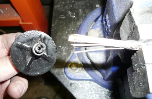
Pulled the tranny and everything else to get to the rear seal, fully expecting a folded lip occurred during installation. Removed the cover and all looks fine. Not sure what to think. I am sure the oil was seaping from the rear seal as where else could it have come from? Here are a couple pics of the seal.
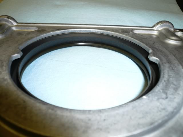
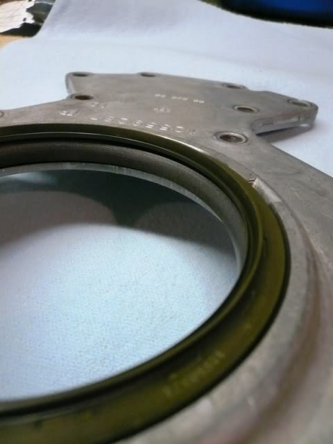
No folds or creases on the seal lips, so I doubt it had been folded.
When I originally put the engine together, I never installed a new rear seal as everything was clean and dry when I pulled the engine apart and the seal looked identical to the brand new one I have. Only thing I can think of is I put a very light film of oil on the seal to help with installation. I understand the rear seal is to be installed dry, so I am wondering if this light film of oil is the cause of my leak?
Turned the ignition to run to set the fuel pressure reg only to find no pressure being built. As this is such a simple circuit in the swap, (PCM R9 through C100, G4 to the fuel pump relay coil) I went right to my fuel pump relay to confirm if I was getting +12 V. Sure enough ignition on +12V at the relay coil, ignition off 0 Volts, PCM circuit is working fine, but relay not picking up. Thinking the relay was toast (brand new Racetronix relay) I threw in a jumper across the fuel pump relay N/O contact to confirm fuel pump operation and set the regulator. Had to leave things at that ,as was heading out to a World Juniors hockey game.
Checking further into the relay problem today, I unplugged the Racetronix relay and tied in a spare relay into the wiring harness. Ignition on, relay did not pick up. Removed relay, check coil circuit again for +12V when ignition is on, sure enough +12V. ??? Checked voltage drop across relay coil when 12V applied and nothing. (Should have seen 12v across the coil, being the full voltage drop of the circuit)
Hooked up the OBDII reader to see if any DTCs were set. Sure enough codes:
P-1626 - Theft Deterrent Fuel Enable Signal Lost. VATS must still be enabled? Hmmm, VATS was to be have been removed with my reprogram.
P-0452 - EVAP Pressure Sensor Low. Must be from not having a tank pressure sensor hooked up? Hmmm, Fuel Pressure sensor was to have been removed with my reprogram.
P-0102 - MAF Low Inlet. With goiing with a Speed Density tune, MAF was to be removed. Hmmm, MAF was to be removed with my reprogram and setup for a Speed Density tune.
Attempted an anti-theft relearn procedure I found on my tuners website, where the forth start sequence is supposed to be the completion of the relearn and a normal start is to occur = failure.
Well, not really happy with my mail order tune right now, so will be tracking down my tuner to discuss further...
So much for a start today, she fired a few times and scared the heck out of my daughter so all was not lost. LOL
THEN,
Oil spill under rear of engine. No way! After kicking myself around the garage for awhile, I went after what I can only assume to be a rear oil seal leak. I was very very careful when I put this cover on and used the GM seal installation tool as well, so was in disbelief when I seen the oil pool.
Pulled the tranny and everything else to get to the rear seal, fully expecting a folded lip occurred during installation. Removed the cover and all looks fine. Not sure what to think. I am sure the oil was seaping from the rear seal as where else could it have come from? Here are a couple pics of the seal.
No folds or creases on the seal lips, so I doubt it had been folded.
When I originally put the engine together, I never installed a new rear seal as everything was clean and dry when I pulled the engine apart and the seal looked identical to the brand new one I have. Only thing I can think of is I put a very light film of oil on the seal to help with installation. I understand the rear seal is to be installed dry, so I am wondering if this light film of oil is the cause of my leak?
01-02-2012, 06:25 AM
#97
Senior Member
iTrader: (5)
Join Date: Dec 2008
Location: Alabama
Posts: 719
Likes: 0
Received 0 Likes
on
0 Posts
Car: 1986 camaro
Engine: ls2
Transmission: FLT stage 6 60e
Axle/Gears: 8.8 with 3.73's
Re: LS1/6 build and swap .. so long SBC
I wouldnt think the film of oil would have caused it to leak.. Ive put my oil pan back on with a good amount of oil on the pan, not in the pan "on the pan" and it sealed back up fine. I did this because I was in a hurry and it takes me less than 30 minutes to remove my pan with a tubular k-member. Hate to hear it not going as you planned man. And btw the electric water pump looks like poo and will cause ur motor to run hot... You should trade straight up with me for a stock one ha ha
01-02-2012, 08:56 AM
#98
Senior Member
Re: LS1/6 build and swap .. so long SBC
hp52ta....is your oil pressure sender leaking? it's in kind of a bad spot to tighten down in the engine bay. were there traces of oil on the block/bellhousing/etc?
i had oil under mine the other day when i had to check my 02 sensors, turned out to be power steering fluid. just had the front end in the air, and my return line wasn't tight enough....
i had oil under mine the other day when i had to check my 02 sensors, turned out to be power steering fluid. just had the front end in the air, and my return line wasn't tight enough....
01-02-2012, 10:36 AM
#99
Re: LS1/6 build and swap .. so long SBC
I am not really convinced it is the rear seal either. Before I removed the rear cover, I tried to identify where the oil was coming from, but with clean oil and the time it takes to pull it apart, it was hard to tell where it originated. I checked around the oil pressure sender too and it seemed to be dry up top.
When I put the engine in the car I remember pouring a quart of oil down the cam position sensor hole before putting in the sensor (Poor man's prelube) so thought this may have been as issue. With everything removed from the rear of the block, you can see the sensor and sensor hole and all was dry and clean around there as well.
I am going to reinstall the rear cover today with the rear seal completely dry. I can't see the light film of oil I put on the seal previously causing such a leak, but after many hours of searching last night, the consensus (and GMs explicit recommendation) is to install the rear seal completely dry onto a completely dry crankshaft, throw on the flywheel and do some start attempts. Seeing that it won't run with the current tune, (pop, fart, quit) I may as well take advantage of the opportunity to help find the leak.
Thanks for the ideas.
Last edited by HP52TA; 01-02-2012 at 10:40 AM.
01-02-2012, 11:36 AM
#100
Supreme Member
iTrader: (5)
Join Date: Jan 2002
Location: Orland Park, IL
Posts: 13,619
Likes: 0
Received 3 Likes
on
3 Posts
Car: 1984 Z28
Engine: SLOW carbed ls
Transmission: TH400 with brake, 8" PTC converter
Axle/Gears: moser 9" 4.11
Re: LS1/6 build and swap .. so long SBC
Every rear main seal I've installed on gen 3/4 motors has been with an oil film on the crank before install. Guess it's the sbc guy inside me, but never installed one dry and no leaks out of the 7 that I've done. They were all fel-pro replacements, not sure if that matters compared to a GM gasket, but I doubt it would.