TPI Injector Swap
By Frank Twardoch ( ftwardoc@mail.portpack.com )
Changing injectors on your TPI motor is not a difficult project, just a bit time consuming.
Make sure you have the following before you start:
- A gasket set for the upper runner to plenum, lower runner to manifold, and throttle body to plenum
-
- Injectors . make sure that what you have is the correct part number.
- A wide range of hand tools to include a Torx socket size T-40 and a torque wrench.
- Disassembly with air tools saves work and time.
- Thread sealant . liquid type . for the intake manifold bolts.
- These instructions!
- Suggest you not drive the vehicle for a few hours prior to beginning this project, in order to allow the relatively high fuel pressure (43.5psi or higher) to bleed down.
Directions:
- Remove the negative cable from your battery and secure. I also took my positive off due to having a direct charge alternator. Can never be too safe.
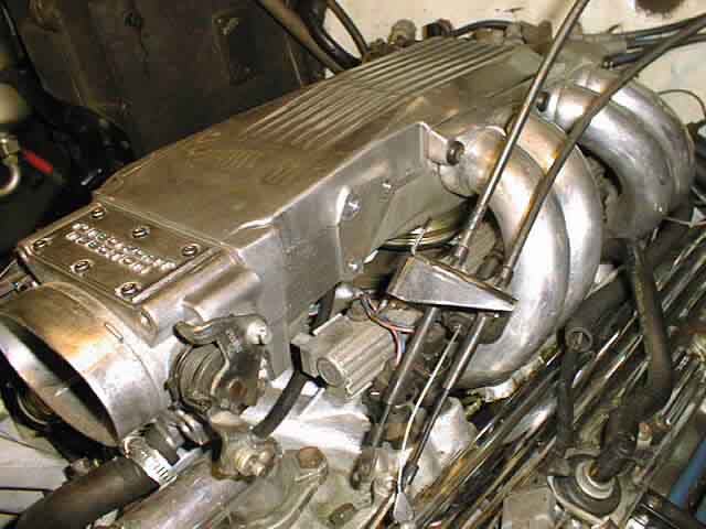
- Begin by removing the air filter from the front of the plenum. This requires a 5/16. socket or screwdriver.
- Disconnect the throttle cable, transmission kickdown cable (or TV cable if you have a 700R4) and the cruise control slotted cable (here applicable) from the throttle body.
- Using a 10mm socket and 10mm combination wrench, remove the three bolts holding the cable bracket to the plenum. Cable tie the cable array to the side, out of the way.
- Unplug the TPS at the front passenger side of the throttle body.
- If you have done a coolant bypass on the throttle body, unplug the IAC (idle air control) motor, and, with a 10mm socket, remove the 4 bolts holding the throttle body to the plenum and set the TB aside. If you have maintained the factory heater/cooling lines to the throttle body, use cable ties to hold the throttle body away from the plenum area. I tied it off to the alternator bracket.
- Remove the 8 top runner-to-plenum bolts, using a T-40 socket.
- Gently lift up on the plenum from front to rear. You will have to remove four connections (more or less, depending on your motor) at this point that go into the plenum. First is the MAT (manifold air temp) sensor, which is located on the bottom side of the plenum, towards the firewall. This is a simple plug. If you have power brakes, there is also a ½. (or comparable) vacuum hose at the very rear of the plenum on the driver.s side that will pull straight off. The last two connections are on the passenger side back near the distributor, both are vacuum connections, usually one is dedicated for the MAP sensor and the other is for various other vacuum actuated items such as the defrost motors, etc. Now that all the connections are free, remove the plenum.
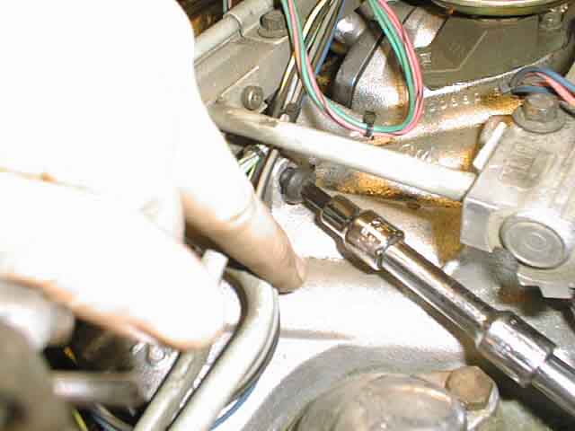
- Remove the lower runner-to-manifold bolts, using the T-40 socket. There are 6 per side. **One bolt per side is hidden and only accessed from inside the manifold area. The one for the passenger side is accessed near the thermostat housing area, and the one for the driver.s side is accessed between the fuel pressure regulator and the distributor. Having a good selection of extensions and a ¼. air ratchet makes removing that driver.s side one easy. LEAVE the bolts in the manifold, it will make it easier than trying to put them back in later.
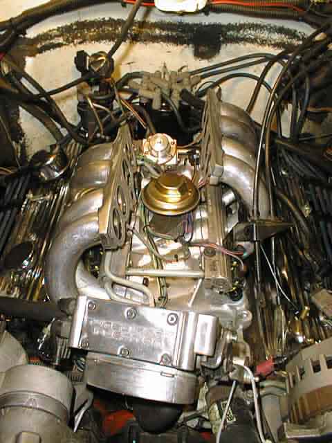
- Remove the passenger side plenum and set aside. IF you have a CSI (cold start injector), which will be on the driver.s side, you will need to first remove the nut holding the fuel supply tube from the fuel rail (using an 18mm end wrench), then you can remove the driver.s side runner.
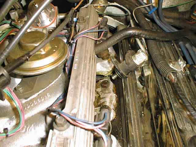
- With many SBC motors, and TPI motors with heads from .87 up, there is a tendency to have oil leakage on the manifold between the two middle manifold-to-head bolts (on both sides), usually brought on by normal shrinkage of the intake manifold gaskets over time, as well as the failure to use thread sealant on the bolts. NOW is the time to remove the center 4 bolts (at least those 4, if not all the bolts one at a time), and coat the threads with a sealant. Then re-torque the manifold bolts, first to 25 lb/ft, then to 45 lb/ft. IF you have aluminum heads, the torque rating is lower, 25 lb/ft. I believe.
- Remove the 8 injector plugs, depending on your wiring harness (I have a Painless), by pushing in on the steel clips and pulling the plug upwards. Tho the TPI system is not a sequential fuel injection system, and therefore all 4 injectors on each side fire at once, I suggest marking the locations (from 1-8) of the respective plug-to-injector, which will make it easier for reassembly and routing of the wiring.
- The fuel rail is the next item to remove. First remove the vacuum line that feeds the FPR (fuel pressure regulator). I have an IROC fuel rail, which exits towards the driver.s side, so the following directions are applicable to that type of fuel rail, but may differ slightly for a Corvette rail that exits to the passenger side. Remove the two fuel lines that connect the fuel rail to the supply hoses. In order to do this, I had to remove the T-40 bolt that holds my alternator to the serpentine belt system, loosen the other alternator mount bolt (15mm), and by using a ½. breaker bar, take tension off the serpentine belt, and un-loop it from the alternator, allowing the alternator to rotate clockwise towards the inner fender. This will allow the room needed to remove the fuel line hookup to the fuel rail, using a 5/8. flare nut wrench (DO NOT use a standard combination wrench) on the fittings and a ¾. end wrench to secure the fuel rail base. There will likely be some fuel dripping so I suggest having a rag under the fittings to absorb the fuel. Route the supply lines away and behind the alternator and set aside. There is a 9/16. nut that secures the front of the fuel rail to the block, remove it. Then, using a 10mm socket, remove the 4 bolts on the fuel rail that hold it to the manifold. You can now carefully pry up on and wiggle the fuel rail until the injectors come out of the manifold. They are a press fit, held in by o-rings, so be careful you don.t peel an o-ring as you remove the rail. Make sure all 8 injectors have the o-rings still on them, if not, use a small pick to retrieve them from the intake manifold). Take the entire fuel rail assembly (with injectors attached) to a well-lit work area for the injector swap.
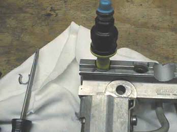
- Turn the fuel rail upside down so you have the injectors facing up. Using a flat blade screwdriver, rotate the clip that holds the injector to the fuel rail to the left (clockwise) only until it reaches the flat area, then grip the injector firmly and wiggle the injector while pulling up on it. It takes a fair amount of effort to remove the injector from the fuel rail, so be aware.
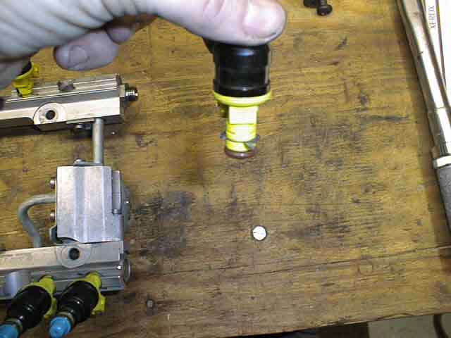
Using a pair of duckbill pliers (my favorite tool), remove the clip from the old injector, and install on the new injector. Using petroleum jelly, or a good o-ring lube, lubricate the new injector.s o-rings (both fuel rail side and manifold side). Then install the new injector, just as you removed the old one, taking care to make sure the retaining clip is in the correct orientation. Then again with the flat blade screwdriver, rotate the clip back to the .starting. position. Pay extremely close attention so you do not damage or cut any of the o-rings when reassembling. Do this process with all 8 injectors and you will be ready to begin the reinstallation.
- Reinstallation is much the reverse of the disassembly. There are a few tips I learned that I believe are important.
- When re-seating the fuel injectors into the manifold, you must ensure they all seat .cleanly., and in fact I heard a satisfying click (well, more a snap) that is not simply accomplished by tightening down the 10mm bolts. Do this in natural sets of 2, as you will see the fuel rail has each pair of injectors near each other. Failure to do this can and will result in fuel leakage and/or vacuum leaks.
- Make sure you are re-routing everything such as the injector plugs very cleanly, and ensure no wires can be pinched.
- Take the time while the fuel rail is off to clean all oil and dirt off the intake manifold using a lint free rag with brake cleaner.
- Put the new Felpro (or equivalent) gasket sets on AFTER you do the cleanup of the manifold areas.
- I strongly suggest you test the o-ring seals prior to putting the runners on. Accomplish this by hooking up the fuel rails and its. supply and return lines, hooking the battery back up, and pressurizing the fuel rails by turning on the ignition switch for a few seconds. Then very carefully smell and visually search for leaks. This step is CRITICAL, for not only time saving if you do have a leak, but for your SAFETY and well-being. Don.t forget to unhook the battery again after pressure checking the injector seals.
- I don.t recommend using air tools on reassembly except to run the bolts down, but not to tighten the bolts. The plenum is aluminum and can and will strip threads easily.
Overall this project took me about 6 hours total, taking my time and having a couple of minor interruptions (hey, food is a good thing!).