Do away with dizzy?
 07-28-2003, 09:41 PM
#1
Supreme Member

Thread Starter

Join Date: Feb 2000
Location: Johnstown, Ohio
Posts: 1,416
Likes: 0
Received 0 Likes
on
0 Posts
Car: 84 Z28
Engine: 355 (fastburn heads, LT4 HOT cam)
Transmission: 700R4
Axle/Gears: 9-bolt, 3.27
Do away with dizzy?
Ok, I know this isn't exactly a PROM burning topic, but it is a DIY-engine management thing, so I think it will fit here!
I have this hair-brained idea to get rid of the distributor on my car. I think all that I need for this is pretty simple. I need a crank sensor, which would be easily adapted from a newer small-block vortec engine (I already have this! I would just need to put the hole in the cover and install the sensor!) and I'm thinking I would use the Northstar ignition module. I haven't done all the legwork on this one yet (I intend to pull up some wiring diagrams tomorrow) but I'm just wondering if anyone else has tried this, or if there are any ideas floating in your heads that may help with this. If thigs work like I think they would, it would adapt to TPI, TBI, or even CC carbed apps!
I have this hair-brained idea to get rid of the distributor on my car. I think all that I need for this is pretty simple. I need a crank sensor, which would be easily adapted from a newer small-block vortec engine (I already have this! I would just need to put the hole in the cover and install the sensor!) and I'm thinking I would use the Northstar ignition module. I haven't done all the legwork on this one yet (I intend to pull up some wiring diagrams tomorrow) but I'm just wondering if anyone else has tried this, or if there are any ideas floating in your heads that may help with this. If thigs work like I think they would, it would adapt to TPI, TBI, or even CC carbed apps!
 07-29-2003, 12:14 AM
#2
Senior Member

Join Date: Jul 2003
Location: The Nest
Posts: 506
Likes: 0
Received 0 Likes
on
0 Posts
Car: 1985 GMC Jimmy/1998 Chevy Malibu
Engine: 3.2L turbo Hybrid/bone stock 3100
Transmission: T-5 soon to be 700R4/4T40E
LOL, I started reading this and thinking: "The North Star ignition would be perfect for a (V8) DIS conversion." 
There are other options for the crank trigger as I can see the cover conversion maybe having extra issues to deal with. like the trigger wheel, somehow attached to the crank, between the damper and the crank timing gear.
There are a couple of other options though:
You could make a bracket for the Crank Postion Sensor and a custom wheel that bolts onto the damper like an aftermarket crank trigger would, then spacing of the rest of the belt driven accessories could be done with shims and washers, to realign the belt, this will take a better look though.
If the NS ignition works like mine does on my V6 (which I believe it does) there will be 6 equally spaced notches, and a single home signal notch 10* before the #1 TDC notch. But this will also take some research into the NS specific ignition, to see what triggers it does need. I say six notches, because even the 4 cyl uses the same number of notches, it seems the module knows that it is a 4, 6 or 8 cylinder module.
Here is a pic of mine for my V6. Mine was custom and basically just mimicked the design of the factory crank trigger wheel, turned a few degrees due to the fact that the Crank Position Sensor now is "sooner" on the crank rotation than where GM put it.
A modified MSD crank trigger may also work, you would have to add an extra magnet at the proper position for the home signal.
The biggest problem I have heard is with the ECM, I know of one person who was trying this on their 3.4L OHV V6 in an S-10, with the stock ECM, and too date I have not heard any success. I have read though that it may be due to the trigger the ECM needs to see being inverted between the DIS and distributer signals, I have not been able to verify this however.
I'd be interested in hearing what you do find out.
Last edited by The_Raven; 07-29-2003 at 12:18 AM.
07-29-2003, 06:26 AM
#3
Supreme Member

Join Date: Jun 2000
Location: In reality
Posts: 7,554
Likes: 0
Received 1 Like
on
1 Post
Car: An Ol Buick
Engine: Vsick
Transmission: Janis Tranny Yank Converter
If your really wanting to do the best possible ignition system, then all you need is a set of LS1 coils, an eDIst, and the right distributor. Then wire as necessary.
Just remember once you swap over, you don't have any ignition until you get a cam pulse. The reason for the odd looking DIS triggers is so that they can figure out what cylinder is firing next instead of having to wait around for cam signal.
But, the LS1 coils are worth it.
Just remember once you swap over, you don't have any ignition until you get a cam pulse. The reason for the odd looking DIS triggers is so that they can figure out what cylinder is firing next instead of having to wait around for cam signal.
But, the LS1 coils are worth it.
07-29-2003, 06:57 AM
#4
Supreme Member
Thread Starter
Join Date: Feb 2000
Location: Johnstown, Ohio
Posts: 1,416
Likes: 0
Received 0 Likes
on
0 Posts
Car: 84 Z28
Engine: 355 (fastburn heads, LT4 HOT cam)
Transmission: 700R4
Axle/Gears: 9-bolt, 3.27
The crank trigger would be all OEM GM stuff like on the 5.7 vortec truck engines, and I possibly mod the trigger wheel for a sync notch. The LS1 coils, I'm sure would be a better idea thoug... More thinking to go on this!
07-29-2003, 11:14 AM
#5
Junior Member

Join Date: Nov 2002
Location: Anderson, Indiana
Posts: 20
Likes: 0
Received 0 Likes
on
0 Posts
What you want to do can be done with the correct trigger wheel; however, the Vortec 4X wheel is not even close to being correct. The N* DIS module can't read any trigger wheel input, only what the electronics is designed to decode.
Keep digging; you'll figure it out. we've done it here and it does work!
Keep digging; you'll figure it out. we've done it here and it does work!
07-29-2003, 02:17 PM
#6
Supreme Member
Join Date: Jun 2000
Location: In reality
Posts: 7,554
Likes: 0
Received 1 Like
on
1 Post
Car: An Ol Buick
Engine: Vsick
Transmission: Janis Tranny Yank Converter
Originally posted by Speartech
Keep digging; you'll figure it out. we've done it here and it does work!
Keep digging; you'll figure it out. we've done it here and it does work!
Silly me I thought this list was about helping others, and sharing info..
07-29-2003, 04:11 PM
#7
Junior Member
Join Date: Nov 2002
Location: Anderson, Indiana
Posts: 20
Likes: 0
Received 0 Likes
on
0 Posts
Because the guy sounds smart enough to figure some stuff out for himself. I think he can make the next logical step and say "hmmm, I wonder what the N* crank wheel looks like?"
I do this stuff for a living, so I don't have time to sit and roam the boards all day like some do.
I contribute when I can and in a way that I think is most beneficial. I could have ignored the post altogether (like you should've) and gone on, but it's interesting enough and the guy is on the ball enough that I thought I would give him some encouragement.
Silly you?.....I don't know, that could probably be a thread all of its own.
Trending Topics
07-29-2003, 04:37 PM
#8
Supreme Member
Join Date: Apr 2002
Location: Armpit state
Posts: 1,119
Likes: 0
Received 0 Likes
on
0 Posts
Car: 71 Nova
Engine: Superramed 383, Topline heads
Transmission: 700r4
Axle/Gears: 8.2 posi 3.08
Thats just plain weak. Everyone here doesnt act like that. If I know something someone else doesnt I make it clear and simple what to do. Anything else just makes it seem like you are makeing **** up. Whatever. I appreciate the people on this board that dont have to act like they are all knowing but dont share.
07-29-2003, 07:52 PM
#9
Supreme Member
Join Date: Jun 2000
Location: In reality
Posts: 7,554
Likes: 0
Received 1 Like
on
1 Post
Car: An Ol Buick
Engine: Vsick
Transmission: Janis Tranny Yank Converter
Originally posted by Speartech
Because the guy sounds smart enough to figure some stuff out for himself. I think he can make the next logical step and say "hmmm, I wonder what the N* crank wheel looks like?"
I do this stuff for a living, so I don't have time to sit and roam the boards all day like some do.
I contribute when I can and in a way that I think is most beneficial. I could have ignored the post altogether (like you should've) and gone on, but it's interesting enough and the guy is on the ball enough that I thought I would give him some encouragement.
Silly you?.....I don't know, that could probably be a thread all of its own.
but you do have time to roam the boards, if your not here to contribute then what are you doing?.
Most beneificial? Excuse me for laughing some more. Most beneifical would be saying this is how you do it, and explaining it. While he might get the drift of it, the idea of the board would appear to be helping everyone / anyone with sharing the how to do it. Not just playing some silly game.
Ya, would be easy to ignore alot of what gets said here and just look for info to use for commercial gain. But, to some the purpose is a two way deal with people charing info., not just commerical guys snooping out info to cash in on.
So how does one impliment what you've inferred works?. Or are you here just to snoop out info to cash in on?.
07-29-2003, 08:12 PM
#10
Senior Member
Join Date: Jul 2003
Location: The Nest
Posts: 506
Likes: 0
Received 0 Likes
on
0 Posts
Car: 1985 GMC Jimmy/1998 Chevy Malibu
Engine: 3.2L turbo Hybrid/bone stock 3100
Transmission: T-5 soon to be 700R4/4T40E
LOL
Anyway, I'm sure you will find that a trigger wheel will trigger the ignition, since hmm, well, all ignitions need some sort of trigger and where do those triggers come from? well most look like wheels, like trigger wheels. Even distributers have parts that you could call a trigger wheel although they are usually refered to as points or reluctors. The ECM just controls the timing.
Anyway, I'm sure you will find that a trigger wheel will trigger the ignition, since hmm, well, all ignitions need some sort of trigger and where do those triggers come from? well most look like wheels, like trigger wheels. Even distributers have parts that you could call a trigger wheel although they are usually refered to as points or reluctors. The ECM just controls the timing.
07-29-2003, 08:23 PM
#11
Supreme Member
Thread Starter
Join Date: Feb 2000
Location: Johnstown, Ohio
Posts: 1,416
Likes: 0
Received 0 Likes
on
0 Posts
Car: 84 Z28
Engine: 355 (fastburn heads, LT4 HOT cam)
Transmission: 700R4
Axle/Gears: 9-bolt, 3.27
Well, I DID have a chance to scope out what the Northstar crank wheel looks like (the shop at which I work at pays thousands of dollars for the software, so I make every use of it that I can!)
If you have some ideas that would make it possible to use such a setup, let me in on it, or if it's only something that is available commercially, link me, but please don't drop in here and just "tease" people with "I've done it"....
Now, in keeping myself from spouting off about board etiquette (sp?), Back to topic.
It seems the Northstar system is a bit more complex than I had anticipated. It uses 2 crank sensors, and a a higher resolution reluctor wheel (many more teeth), along with a high resolution cam sensor. Far more than I thought it would be, so, I think I'm dropping that particular system. I was thinking (more like hoping) that it would be as simple as the late 80's 2.8/3.1 FWD DIS, where I could simply use a modified vortec crank wheel. I have a few other ideas in mind, such as the vortec distributor, LS1 system....who knows what else I may come up with.
On a final note.....Thanks to the ones that have the time to sit and roam the boards "all day". These guys have some great experience that I have learned from by just spending a few hours a wekk on these boards...
07-29-2003, 09:05 PM
#12
Supreme Member
Thread Starter
Join Date: Feb 2000
Location: Johnstown, Ohio
Posts: 1,416
Likes: 0
Received 0 Likes
on
0 Posts
Car: 84 Z28
Engine: 355 (fastburn heads, LT4 HOT cam)
Transmission: 700R4
Axle/Gears: 9-bolt, 3.27
I guess my main issue is finding an ignition system (I think Grumpy mentioned the eDist???) that will work with the GM ECM timing control....
I was interested in keeping with OE parts for that reason, along with parts availability. I'll see what else I can turn up!
BTW....Any linkage for the eDist?
I was interested in keeping with OE parts for that reason, along with parts availability. I'll see what else I can turn up!
BTW....Any linkage for the eDist?
07-29-2003, 09:09 PM
#13
Senior Member
Join Date: Jul 2003
Location: The Nest
Posts: 506
Likes: 0
Received 0 Likes
on
0 Posts
Car: 1985 GMC Jimmy/1998 Chevy Malibu
Engine: 3.2L turbo Hybrid/bone stock 3100
Transmission: T-5 soon to be 700R4/4T40E
JP8, look deeper into the northstart system I have a feeling it's set-up ALOT like the newer V6 SFI, where the crank sensor runs to the ignition and the 24x crank sensor and cam sensor both go to the ECM and are used for the fuel delivery aspect more.
I do have the access to the files you do, but I seem to know how GM thinks on a lot of different areas, and they also seem to like simiarity between different engines, platforms etc.
I do have the access to the files you do, but I seem to know how GM thinks on a lot of different areas, and they also seem to like simiarity between different engines, platforms etc.
Last edited by The_Raven; 07-29-2003 at 11:52 PM.
07-29-2003, 09:15 PM
#14
Supreme Member
Thread Starter
Join Date: Feb 2000
Location: Johnstown, Ohio
Posts: 1,416
Likes: 0
Received 0 Likes
on
0 Posts
Car: 84 Z28
Engine: 355 (fastburn heads, LT4 HOT cam)
Transmission: 700R4
Axle/Gears: 9-bolt, 3.27
Well, I agree with the thinking of similarity between platforms....Until you get to Cadilac. I'm not so sure I want to go through with makinga trigger wheel for it. I do have someone that could EASILY turn out something like that (I could if I had access to the equipment!) but I'm still not liking the 24x for the cam. Maybe I'll get my hands on a module/coils and paly around with it.
Thanks for all the help so far!
Thanks for all the help so far!
07-29-2003, 09:32 PM
#15
Supreme Member
Thread Starter
Join Date: Feb 2000
Location: Johnstown, Ohio
Posts: 1,416
Likes: 0
Received 0 Likes
on
0 Posts
Car: 84 Z28
Engine: 355 (fastburn heads, LT4 HOT cam)
Transmission: 700R4
Axle/Gears: 9-bolt, 3.27
Quick update...
I found the eDist on th web, but I have yet to see any pricing. They only have 1 distributor in the state (Ohio), and it's not near me. I may have to put in some phone calls soon to see what's out there.
I also need to know if it will work with the GM ECM timing stuff (EST system)
I found the eDist on th web, but I have yet to see any pricing. They only have 1 distributor in the state (Ohio), and it's not near me. I may have to put in some phone calls soon to see what's out there.
I also need to know if it will work with the GM ECM timing stuff (EST system)
07-29-2003, 10:07 PM
#16
Supreme Member

Join Date: Jun 2001
Location: Charleston, SC
Posts: 9,550
Likes: 0
Received 2 Likes
on
2 Posts
Car: 91 Camaro Vert
Engine: 02 LS1, HX40
Transmission: 2002 LS1 M6
i think there are a few aftermarket crank triggered ignition systems.....
theres also a company that sells a LS1 coil pack conversion
might want to look into how thoes work......
theres also a company that sells a LS1 coil pack conversion
might want to look into how thoes work......
07-29-2003, 10:14 PM
#17
Supreme Member
Join Date: Jun 2000
Location: In reality
Posts: 7,554
Likes: 0
Received 1 Like
on
1 Post
Car: An Ol Buick
Engine: Vsick
Transmission: Janis Tranny Yank Converter
Originally posted by Speartech
I do this stuff for a living, so I don't have time to sit and roam the boards all day like some do.
I contribute when I can and in a way that I think is most beneficial.
I do this stuff for a living, so I don't have time to sit and roam the boards all day like some do.
I contribute when I can and in a way that I think is most beneficial.
To: gmecm@diy-efi.org
Subject: Re: DIS for GMECM
From: Speartech <speartec@iquest.net>
Date: Tue, 05 Dec 2000 23:26:07 -0500
Reply-to: gmecm@diy-efi.org
Sender: owner-gmecm@lists.diy-efi.org
...................................
No words can cover this.
07-29-2003, 10:17 PM
#18
Supreme Member
Join Date: Jun 2000
Location: In reality
Posts: 7,554
Likes: 0
Received 1 Like
on
1 Post
Car: An Ol Buick
Engine: Vsick
Transmission: Janis Tranny Yank Converter
Originally posted by JP84Z430HP
Quick update....
I found the eDist on th web, but I have yet to see any pricing. They only have 1 distributor in the state (Ohio), and it's not near me. I may have to put in some phone calls soon to see what's out there.
I also need to know if it will work with the GM ECM timing stuff (EST system)
Quick update....
I found the eDist on th web, but I have yet to see any pricing. They only have 1 distributor in the state (Ohio), and it's not near me. I may have to put in some phone calls soon to see what's out there.
I also need to know if it will work with the GM ECM timing stuff (EST system)
Just tied the oem module to coil connections with 1K resistors, and then used the negative side of the resistors as the EST signal to the eDist.
The FAST ecm generates an EST signal at crank speeds where as the GM ignitions use the module only for crank.
I think retail is about $300 on them.
07-29-2003, 10:32 PM
#19
Supreme Member

Join Date: Jun 2002
Location: great lakes
Posts: 1,787
Likes: 0
Received 0 Likes
on
0 Posts
im going to help a bit here. those 2 cranks signals arent needed. you need the low res 9 pulse wheel pattern. you may discard the cam as well the icm is simply converting the vrs into a halleffect. the secondary 27 tooth wheel is primarily to help the icm determine where the crank is in 180 of first crank. i might be wrong which ever whel has an offset tooth will be the one to copy. you can discard one of the crank signals im a bit fuzzy on which one im being honest here. now to rn that for boos youll need $8f in a 727/730 and for non boost any dis v6 code will work. if you wish to run * 58 theres a few thing need to happen code wise or any other non dis code. the min and max advance setting must be swapped with each other. secondly discrad the 24x 6x ref line and use the tach ouput for your ref pulse. the ecm will go bongo otherwise.
just advice and tidbits ive picked up putting a dis gm ecm together for my accord and my caprice with tpi. peace out.
or you could use 2 4cyl dis modules and run the sensors 180 out of phase and tie the est and the ref lines etc into a t . being 180 out of phase though will require experimenting with the firing order to get it right. but just make sure to put a clamping diode onto the est ect ect before the t going to the ecm so you dont get a back feed.
Last edited by funstick; 07-29-2003 at 10:47 PM.
07-29-2003, 10:54 PM
#20
Supreme Member
Thread Starter
Join Date: Feb 2000
Location: Johnstown, Ohio
Posts: 1,416
Likes: 0
Received 0 Likes
on
0 Posts
Car: 84 Z28
Engine: 355 (fastburn heads, LT4 HOT cam)
Transmission: 700R4
Axle/Gears: 9-bolt, 3.27
Thanks Funstick for your HELPFUL input. I may not scrap the Northstar setup after all. I'm gonna have to look at the documentation I printed out at work (and forgot to bring home!) and see what I can do! This could be getting interesting!
I was actually thinking what it would take to get 2 4 cyl modules runnig together, but that would still require a special trigger wheel. Even though the thing doesn't do anything on the "extra" notches (the ones the v-6 would use) it has to see them, correct? If I have to make a trigger wheel, I would rather just go with the Northstar system.... One up-side to using both crank sensors would be faster starting (theory). I know, the 3800's "Fast start" system didn't seem any different in starting times to me though!
As for the eDist setup, it sounds like you still HAVE to run the original ignition module. I'd really rather not have that thing even near the car! (I just don't care for the modules in the HEI stuff! At first, the DIS stuff wasn't any better, maybe worse, but it's come a long way!)
I have some time to think about this, and maybe even experiment on the S-10 before the V-8 goes into it.
BTW.....Anyone ever run a TBI setup with a 730? I'm thinking about trying it on the 2.8 S-10 and using a MEMCAL from a 2.8 MPFI to get the KS circuitry correct. This is a temporary project to get into the ECM tuning.....
I was actually thinking what it would take to get 2 4 cyl modules runnig together, but that would still require a special trigger wheel. Even though the thing doesn't do anything on the "extra" notches (the ones the v-6 would use) it has to see them, correct? If I have to make a trigger wheel, I would rather just go with the Northstar system.... One up-side to using both crank sensors would be faster starting (theory). I know, the 3800's "Fast start" system didn't seem any different in starting times to me though!
As for the eDist setup, it sounds like you still HAVE to run the original ignition module. I'd really rather not have that thing even near the car!
(I just don't care for the modules in the HEI stuff! At first, the DIS stuff wasn't any better, maybe worse, but it's come a long way!) I have some time to think about this, and maybe even experiment on the S-10 before the V-8 goes into it.
BTW.....Anyone ever run a TBI setup with a 730? I'm thinking about trying it on the 2.8 S-10 and using a MEMCAL from a 2.8 MPFI to get the KS circuitry correct. This is a temporary project to get into the ECM tuning.....
07-29-2003, 10:59 PM
#21
Supreme Member
Thread Starter
Join Date: Feb 2000
Location: Johnstown, Ohio
Posts: 1,416
Likes: 0
Received 0 Likes
on
0 Posts
Car: 84 Z28
Engine: 355 (fastburn heads, LT4 HOT cam)
Transmission: 700R4
Axle/Gears: 9-bolt, 3.27
SO the northstar ICM operates (interfaces with the ECM) pretty much the same as the good ole 2.8/3.1 ICM I've seen since 1987? Interesting...... Must not be that bad a design....
07-29-2003, 11:07 PM
#22
Supreme Member
Join Date: Jun 2000
Location: In reality
Posts: 7,554
Likes: 0
Received 1 Like
on
1 Post
Car: An Ol Buick
Engine: Vsick
Transmission: Janis Tranny Yank Converter
Originally posted by funstick
if you wish to run * 58 theres a few thing need to happen code wise
if you wish to run * 58 theres a few thing need to happen code wise
07-29-2003, 11:15 PM
#23
Supreme Member
Join Date: Jun 2002
Location: great lakes
Posts: 1,787
Likes: 0
Received 0 Likes
on
0 Posts
but that would still require a special trigger wheel
i think with 2 moduels it would work ut in pairs
1-4
3-7
5-8
2-6
with coils on the tdc module firing
1,3,5,7
and thre bottom pair
2,4,6,8
or something like that id have to pull out a crank and walk through the firing order. mind you 2 4cyl moduels new with coils are still cheaper the 1 n* dis module
07-29-2003, 11:20 PM
#24
Supreme Member
Join Date: Jun 2002
Location: great lakes
Posts: 1,787
Likes: 0
Received 0 Likes
on
0 Posts
if you wish to run * 58 theres a few thing need to happen code wise or any other non dis code. the min and max advance setting must be swapped with each other
on second thought the crank sensor for a dual modul setup need to be 90* apart ill explian tommorow when the codine wears off from me breaking my hand today.
Last edited by funstick; 07-29-2003 at 11:27 PM.
07-30-2003, 12:04 AM
#25
Senior Member
Join Date: Jul 2003
Location: The Nest
Posts: 506
Likes: 0
Received 0 Likes
on
0 Posts
Car: 1985 GMC Jimmy/1998 Chevy Malibu
Engine: 3.2L turbo Hybrid/bone stock 3100
Transmission: T-5 soon to be 700R4/4T40E
Originally posted by JP84Z430HP
SO the northstar ICM operates (interfaces with the ECM) pretty much the same as the good ole 2.8/3.1 ICM I've seen since 1987? Interesting...... Must not be that bad a design....
SO the northstar ICM operates (interfaces with the ECM) pretty much the same as the good ole 2.8/3.1 ICM I've seen since 1987? Interesting...... Must not be that bad a design....
Just so you can see the physical similarities between the V6 coil pack and the N* coil pack, here is a picture of mine.
The code will still have to be worked out, but I have a feeling funstick, knows how.
07-30-2003, 06:26 AM
#26
Supreme Member
Join Date: Jun 2000
Location: In reality
Posts: 7,554
Likes: 0
Received 1 Like
on
1 Post
Car: An Ol Buick
Engine: Vsick
Transmission: Janis Tranny Yank Converter
Originally posted by funstick
i already stated what needed to change. also and i havent had a chance to confirm this but someone else is the regular dis module puts out a 6x ref pulse ( which i blieve is the spark advance gremlin that an umentioned person ) was having.
i already stated what needed to change. also and i havent had a chance to confirm this but someone else is the regular dis module puts out a 6x ref pulse ( which i blieve is the spark advance gremlin that an umentioned person ) was having.
On the GN DIS the tach signal output isn't even used.
07-30-2003, 06:28 AM
#27
Supreme Member
Join Date: Jun 2000
Location: In reality
Posts: 7,554
Likes: 0
Received 1 Like
on
1 Post
Car: An Ol Buick
Engine: Vsick
Transmission: Janis Tranny Yank Converter
Date: Tue, 05 Dec 2000 23:26:07 -0500
From: Speartech <speartec@iquest.net>
Subject: Re: DIS for GMECM
Sender: owner-gmecm@diy-efi.org
To: gmecm@diy-efi.org
I'll just let this go without comment.
For the new guys got to DIYEFI.ORG and click on GMECM, then archives, then Dec 2000, and then look under authors and then this date.
From: Speartech <speartec@iquest.net>
Subject: Re: DIS for GMECM
Sender: owner-gmecm@diy-efi.org
To: gmecm@diy-efi.org
I'll just let this go without comment.
For the new guys got to DIYEFI.ORG and click on GMECM, then archives, then Dec 2000, and then look under authors and then this date.
07-30-2003, 10:50 AM
#28
Supreme Member
Join Date: Jun 2002
Location: great lakes
Posts: 1,787
Likes: 0
Received 0 Likes
on
0 Posts
On the GN DIS the tach signal output isn't even used
hhmm i wonder why ?? ahh becuase it doesnt carry the proper signals for the ecm to calculate crank and cam position so it wouldnt be able to run sequetially
07-30-2003, 12:40 PM
#29
Supreme Member
Join Date: Jun 2000
Location: In reality
Posts: 7,554
Likes: 0
Received 1 Like
on
1 Post
Car: An Ol Buick
Engine: Vsick
Transmission: Janis Tranny Yank Converter
Originally posted by funstick
hhmm i wonder why ?? ahh becuase it doesnt carry the proper signals for the ecm to calculate crank and cam position so it wouldnt be able to run sequetially
hhmm i wonder why ?? ahh becuase it doesnt carry the proper signals for the ecm to calculate crank and cam position so it wouldnt be able to run sequetially
The tach signal is for the TACH. The EST and Cam Synch are for the timing and fuel. Your the one that inferred it had something to do with anything ecm wise, which it doesn't.
Since it has nothing to do with anthing ecm wise, why did you even mention it as a source of the problem for the other guy?.
Never mind........
07-30-2003, 06:10 PM
#30
Supreme Member
Thread Starter
Join Date: Feb 2000
Location: Johnstown, Ohio
Posts: 1,416
Likes: 0
Received 0 Likes
on
0 Posts
Car: 84 Z28
Engine: 355 (fastburn heads, LT4 HOT cam)
Transmission: 700R4
Axle/Gears: 9-bolt, 3.27
Ok, I looked into the Northstar system a bit more, and I think it would actually be pretty simple! Since I have a few different sources for machine work, and some CAD background (I'm rusty on it though!) I think I could easily, and relatively inexpensively do this.
For a trigger wheel, I was thinking about just having some notches put into a harmonic balancer, then fabbing up a bracket to hold the sensor, and I could even design in some timing adjustment. My other thought was to make an internal reluctor wheel that would go in the place of the Vortec wheel, that would have the proper notches in it, and use the Vortec sensor.
One thing I need ot find out is where on the Northstar reluctor wheel is #1 TDC in order to get it to work......
The bad news of all this is that it would be several months before I could implement this, unless the wiring/signals would be compatible with my carbed HEI (CCC) system (LG4). If it would work with what I'm running right now, this could be just a few weeks off.
Again, thanks for all the info! Even if this doesn't work, or if I don't get to do it, I have definately learned some here, and I know we all can appreciate a good learning experience!
07-30-2003, 06:22 PM
#31
Supreme Member
Join Date: Jun 2000
Location: In reality
Posts: 7,554
Likes: 0
Received 1 Like
on
1 Post
Car: An Ol Buick
Engine: Vsick
Transmission: Janis Tranny Yank Converter
Originally posted by JP84Z430HP
The bad news of all this is that it would be several months before I could implement this, unless the wiring/signals would be compatible with my carbed HEI (CCC) system (LG4). If it would work with what I'm running right now, this could be just a few weeks off.
The bad news of all this is that it would be several months before I could implement this, unless the wiring/signals would be compatible with my carbed HEI (CCC) system (LG4). If it would work with what I'm running right now, this could be just a few weeks off.
07-30-2003, 07:29 PM
#32
Supreme Member
Thread Starter
Join Date: Feb 2000
Location: Johnstown, Ohio
Posts: 1,416
Likes: 0
Received 0 Likes
on
0 Posts
Car: 84 Z28
Engine: 355 (fastburn heads, LT4 HOT cam)
Transmission: 700R4
Axle/Gears: 9-bolt, 3.27
Well, as soon as I can get my hands on one, I'll have to give it a spin.....Or no spin, or.......
07-30-2003, 10:08 PM
#33
Senior Member
Join Date: Jul 2003
Location: The Nest
Posts: 506
Likes: 0
Received 0 Likes
on
0 Posts
Car: 1985 GMC Jimmy/1998 Chevy Malibu
Engine: 3.2L turbo Hybrid/bone stock 3100
Transmission: T-5 soon to be 700R4/4T40E
I also thought about notching the harmonic balancer, but due to the design of what it is supposed to do, the notches would not be a true refernce signal to crank postion and would most likely cause an out of balance situation.
Take a look at MSD, thay make custom trigger kits that use bolts with a magnet in the head, that are ment for custom instalations into the flywheel, but that may be more work than it's worth for this. You would also need to use the MSD sensor.
There was one guy on the diy-efi list that used bolts welded to the crank pulley at the proper postions and that worked for him, using the stock sensor, depending on space this may also be feasable.
I feel that the trigger wheel based off the OEM design would probably work best.
07-31-2003, 05:57 AM
#34
Supreme Member
Join Date: Jun 2000
Location: In reality
Posts: 7,554
Likes: 0
Received 1 Like
on
1 Post
Car: An Ol Buick
Engine: Vsick
Transmission: Janis Tranny Yank Converter
Originally posted by The_Raven
I also thought about notching the harmonic balancer, but due to the design of what it is supposed to do, the notches would not be a true refernce signal to crank postion and would most likely cause an out of balance situation.
I feel that the trigger wheel based off the OEM design would probably work best.
07-31-2003, 09:21 AM
#35
Supreme Member
Join Date: Jun 2002
Location: great lakes
Posts: 1,787
Likes: 0
Received 0 Likes
on
0 Posts
Take a look at MSD, thay make custom trigger kits that use bolts with a magnet in the head, that are ment for custom instalations into the flywheel, but that may be more work than it's worth for this. You would also need to use the MSD sensor.
07-31-2003, 06:20 PM
#36
Senior Member

Join Date: May 2001
Location: Hollywood, FL
Posts: 502
Likes: 0
Received 0 Likes
on
0 Posts
Car: 78 Regal
Engine: 82 FBod LG4 305, 730 ECM
Transmission: M20
Axle/Gears: 4.10
The MSD stuff will not work as it is used with a distributor, either normal mount or front mount. It doesn't have a TDC reference. AFAIK, no one has gotten a V8 DIS to work with waste spark and the factory ECM. And if someone has made it work, that person ain't saying. There has been some really good theory flying around, but no actual running system. Aftermarket ecm's and DIS is another story.
07-31-2003, 06:37 PM
#37
Senior Member
Join Date: Jul 2003
Location: The Nest
Posts: 506
Likes: 0
Received 0 Likes
on
0 Posts
Car: 1985 GMC Jimmy/1998 Chevy Malibu
Engine: 3.2L turbo Hybrid/bone stock 3100
Transmission: T-5 soon to be 700R4/4T40E
I only suggested the MSD parts, because it was suggest it may work with the factory ignition module, at least when we were discussing my set-up. The home signal can be added as MSD now makes a universal trigger kit where you add the notches where they must go. But if the signal will not work with the factory DIS, that is the larger problem. regardles of how the trigger wheel was designed to be used with/for.
You could always just use their brackets to hold the factory crank trigger, I don't remember if you can but each part seperate or not.
Grumpy, what do you mean by "boat pieces"?
Funstick, can you explain a little more in depth, about the differences in signals, AFAIK, the only difference between the 2 designs is that one has the magnet mounted in the sensor (GM) and the MSD use the magnets in the wheel. Is it because of teh magnet being mounted in the sensor, probably inside a coil that causes the A/C swing that you are talking about? That is about all I can think of.
07-31-2003, 06:42 PM
#38
Supreme Member

Join Date: Jun 2000
Location: the garage
Posts: 1,612
Likes: 0
Received 0 Likes
on
0 Posts
Car: 84 SVO
Engine: Volvo headed 2.3T
Transmission: WCT5
Axle/Gears: 8.8" 3.73
Originally posted by The_Raven
Grumpy, what do you mean by "boat pieces"?
Grumpy, what do you mean by "boat pieces"?
From: Speartech <speartec@iquest.net>
Subject: Re: DIS for GMECM
Sender: owner-gmecm@diy-efi.org
To: gmecm@diy-efi.org
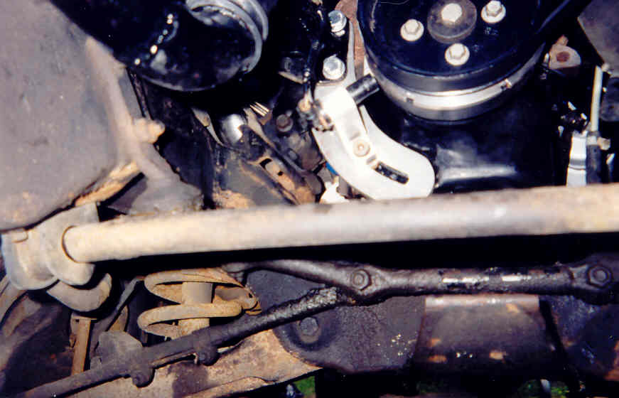
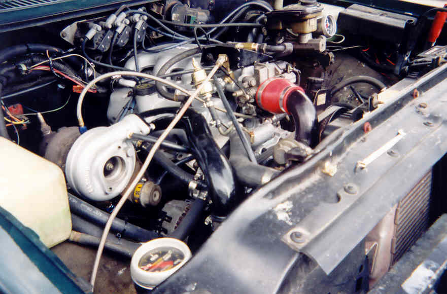
Exactly!! Makes me think back to the LT1 Optispark distributor. All the hoopla about 1 degree resolution with the 360 deg optical sensor, and then go and hook it all together with a timing chain and a little splined drive off the front of the camshaft! Many folks are unaware of the fact that when the LT1's were used in the Mastercraft ski boats, they used the Northstar DIS, NOT the Optispark. The Nstar reluctor wheel mounts on the back of the harmonic balancer, and a new timing chain cover is used with the 2 crank sensor mounting saddles cast right into the cover. It's a neat little package! The 2 crank sensors feed directly into the full-function DIS module, it decodes and processes the signals, and then you have the usual connection to the ECM (REF HI, REF LO, BYPASS, and EST. In the marine application they used the MEFI-2 controller, but hey, it COULD have been a 730/727 controller.

Look at the front of the left head.... HMMMMMMM!!!

BW
Last edited by SATURN5; 07-31-2003 at 07:10 PM.
07-31-2003, 08:00 PM
#39
Supreme Member
Join Date: Jun 2002
Location: great lakes
Posts: 1,787
Likes: 0
Received 0 Likes
on
0 Posts
now thats pretty kewl i was unaaware of the n* dis modules being used on boats hmm i may have to call mercruiser and get a balancer and a timing cover.
As for the signals the pole pie e on the GM vrs sensor generate an AC volatge. it works like an A/C genrator when the metal goes by it creates current when there is a notch. the magnatic feild collapses and createts a signal.
when a hal effect is used there is not pole piece its a bit of metal wrapped with a coil and create a DC feild. this DC filed only goe in one direction towards positive. thats why you need a manget in the trigger wheel to create a field.but the filed only goe in one direction.
the VRS is A/C current and when the notch moves by halfway across its span the current goes from positive to negative. when this occurs there is a a zero crossing. the DIS module is looking for this change from positive to negative. thats how it determine where the teeth are and that one even went by. dalec electronics sells all varietys and sizes of vrs sensor. im currently using a wells cps1 which is a ford edis snesor. it has wiring built in and is extermly easy to mount because it can be clamped or glue or how ever you need to fasten it. its also a great deal smaller then a factory sensor making it much easier to work with. but the airgap needs to be fairly tight for it to generate enough volatge to work effectively. so runout becomes paramount.
07-31-2003, 08:21 PM
#40
Supreme Member
Thread Starter
Join Date: Feb 2000
Location: Johnstown, Ohio
Posts: 1,416
Likes: 0
Received 0 Likes
on
0 Posts
Car: 84 Z28
Engine: 355 (fastburn heads, LT4 HOT cam)
Transmission: 700R4
Axle/Gears: 9-bolt, 3.27
Hmmm...Are the "Boat Pieces" still available? I would think so, but I'm just guessing.... That sounds like it may be the way to go though.
I think I'm still gonna do a CAD drawing of what I was htinking, which sounds pretty much the same as the boat pieces minus the second sensor hole...
This system is almost putting itself together!
Read earlier in the post, it has been done!
I think I'm still gonna do a CAD drawing of what I was htinking, which sounds pretty much the same as the boat pieces minus the second sensor hole...
This system is almost putting itself together!
AFAIK, no one has gotten a V8 DIS to work with waste spark and the factory ECM.
07-31-2003, 08:58 PM
#41
Supreme Member
Join Date: Jun 2000
Location: the garage
Posts: 1,612
Likes: 0
Received 0 Likes
on
0 Posts
Car: 84 SVO
Engine: Volvo headed 2.3T
Transmission: WCT5
Axle/Gears: 8.8" 3.73
This is $58 specific, however should provide clues for other masks.
To: gmecm@efi332.eng.ohio-state.edu
Subject: Hallelujah, I figured it out, or How to use a SyTy .bin with DIS
From: Tedscj@aol.com
Date: Thu, 4 Mar 1999 21:28:24 EST
Reply-to: gmecm@efi332.eng.ohio-state.edu
Sender: owner-gmecm@efi332.eng.ohio-state.edu
--------------------------------------------------------------------------------
I figured out how to get the reference pulses in sync with a SyTy .bin
I'll try to make this short but complete.
The Reference Pulse put out by the DIS module to the ECM is 70 degrees too far
advanced in comparison to what a HEI module would put out. So when the ECM
sends back the EST signal, it too is 70degrees too far advanced. Needless to
say, this causes drivability problems.
In Promgrammer '98, which programs SyTy bins, there is a KREFANGL value.
According to the P4 document (which describes the inner workings of the SyTy
Eprom) this KREFANGL is supposed to adjust for any difference between TDC and
the Reference Pulse timing.
The problem I was having is that no matter what value I put in for the
KREFANGL, nothing happened or changed.
So the solution is in KMAXRTRD2. This, according to the P4 Document is
supposed to be the maximum amount of retard *relative to KREFANGL*.
Apparently this is wrong. When I adjusted this value to 70dgrees it allowed
me to adjust KREFANGL back 70 degrees. And now everything is timed right.
So to sum up: You adjust KMAXRTRD2 to 70 and KREFANGL to 70, and then EST
signal comes in sync with the DIS module and everything SEEMS to be working.
Ted
PS The 70 degrees comes from: 60degrees is how far the reference pulse is
off PLUS 10degrees is how far advanced the DIS is in EST BYPASS mode for a
total of 70degrees.
To sum up...
A northstar coil pack (early) along with a northstar reluctor wheel or facimile on the crank, with the above mentioned timing cover and adjustments to the bin file.. should get you in the ballpark. Lots of reading in the GMECM/DIYEFI archives....
07-31-2003, 09:08 PM
#42
Supreme Member
Thread Starter
Join Date: Feb 2000
Location: Johnstown, Ohio
Posts: 1,416
Likes: 0
Received 0 Likes
on
0 Posts
Car: 84 Z28
Engine: 355 (fastburn heads, LT4 HOT cam)
Transmission: 700R4
Axle/Gears: 9-bolt, 3.27
I know this may sounds simple (Or even stupid) but is it possible that the DIS trigger wheel was/is 60 degrees asdvanced? I guess I'm just not catching on tho this right now, maybe after I look at it a bit more....
I plan to mess with a V-6 DIS setup on a non DIS setup if I can get the trigger wheel made easily enough...
The Raven....Did you have to do anything to get your DIS working? What ECM and base .bin are you working with?
I plan to mess with a V-6 DIS setup on a non DIS setup if I can get the trigger wheel made easily enough...
The Raven....Did you have to do anything to get your DIS working? What ECM and base .bin are you working with?
Last edited by JP84Z430HP; 07-31-2003 at 09:10 PM.
07-31-2003, 09:16 PM
#43
Supreme Member
Join Date: Jun 2002
Location: great lakes
Posts: 1,787
Likes: 0
Received 0 Likes
on
0 Posts
BTW the min and max advance setting need to be swapped and the ref angle is fine BTW. plus you cant use the 6x ref you have to use the tach output. the 6x signal screw up the tpu code in the $58 code. but then again what would i know ?
07-31-2003, 10:40 PM
#44
Supreme Member
Join Date: Jun 2000
Location: the garage
Posts: 1,612
Likes: 0
Received 0 Likes
on
0 Posts
Car: 84 SVO
Engine: Volvo headed 2.3T
Transmission: WCT5
Axle/Gears: 8.8" 3.73
Originally posted by funstick
BTW the min and max advance setting need to be swapped and the ref angle is fine BTW. plus you cant use the 6x ref you have to use the tach output. the 6x signal screw up the tpu code in the $58 code. but then again what would i know ?
BTW the min and max advance setting need to be swapped and the ref angle is fine BTW. plus you cant use the 6x ref you have to use the tach output. the 6x signal screw up the tpu code in the $58 code. but then again what would i know ?

Have you ever run DIS on a TPI V8?... or is this your Honda with fragile axles?
That chap has..
08-01-2003, 12:04 AM
#45
Senior Member
Join Date: Jul 2003
Location: The Nest
Posts: 506
Likes: 0
Received 0 Likes
on
0 Posts
Car: 1985 GMC Jimmy/1998 Chevy Malibu
Engine: 3.2L turbo Hybrid/bone stock 3100
Transmission: T-5 soon to be 700R4/4T40E
Originally posted by JP84Z430HP
I know this may sounds simple (Or even stupid) but is it possible that the DIS trigger wheel was/is 60 degrees asdvanced? I guess I'm just not catching on tho this right now, maybe after I look at it a bit more....
I know this may sounds simple (Or even stupid) but is it possible that the DIS trigger wheel was/is 60 degrees asdvanced? I guess I'm just not catching on tho this right now, maybe after I look at it a bit more....
IIRC the home signal on my crank was at #1 TDC, or just before, but I'll have to drop the crank in the block I'm working on now to verify, but then again, V8 and V6 home signals may not be in sync relative to #1 in comparison.
Originally posted by JP84Z430HP
I plan to mess with a V-6 DIS setup on a non DIS setup if I can get the trigger wheel made easily enough...
The Raven....Did you have to do anything to get your DIS working? What ECM and base .bin are you working with?
I plan to mess with a V-6 DIS setup on a non DIS setup if I can get the trigger wheel made easily enough...
The Raven....Did you have to do anything to get your DIS working? What ECM and base .bin are you working with?
I know that doesn't help your situation but that's what I am doing at this point.I am very interested in knowing what is to be changed in a "non DIS .bin" and so I continue to read this thread.
08-01-2003, 06:56 AM
#46
Supreme Member
Thread Starter
Join Date: Feb 2000
Location: Johnstown, Ohio
Posts: 1,416
Likes: 0
Received 0 Likes
on
0 Posts
Car: 84 Z28
Engine: 355 (fastburn heads, LT4 HOT cam)
Transmission: 700R4
Axle/Gears: 9-bolt, 3.27
We've been told what needs to be changed, but my issue is that I just don't quite understand why! I really need to get my hands on the source code for each, and learn it inside out, then I'm sure I could get it....
For my V-6 project, I planned on trying pretty much the same thing you did. I was going to start with a .bin from a DIS car to get it working, as it should be close to what I need anyway. This has me REALLY thinking now! I suppose I could get an F-car .bin from a 91-92 3.1 car and see what I can do....
Now for the toughy, where can I get commented disassemblies of the code for various apps? I've only seen a couple floating around, and I really want to learn what's goin on with the stuff! Otherwise, how does one do such a task? I'm sure it's very time consuming, and would probably require an ECM bench....
08-01-2003, 07:00 AM
#47
Senior Member
Join Date: May 2001
Location: Hollywood, FL
Posts: 502
Likes: 0
Received 0 Likes
on
0 Posts
Car: 78 Regal
Engine: 82 FBod LG4 305, 730 ECM
Transmission: M20
Axle/Gears: 4.10
funstick, I don't think this is relevant to the thread but what are you talking about with the hall effect making dc voltage? A pick up coil or hall effect will make ac voltage but it's not the voltage that matters. If you don't bellieve that a hall effect will run a GM module, you're crazy. MSD dist's and Chrysler dist's are hall effect and guess what, they will run a GM module as the break in the signal is what's being used. The module processes the info and sends it to the ecm as square wave DC.
And JP84, knock yourself out building a system but I will stick to my earlier research into this. No one has made it work with a factory ecm (165/730). Again, notice where it says it "should work with a 727/730". And the few people that have gotten it to work have not been V8 cars. Don't think for a moment that there won't need to be any code changes.
And JP84, knock yourself out building a system but I will stick to my earlier research into this. No one has made it work with a factory ecm (165/730). Again, notice where it says it "should work with a 727/730". And the few people that have gotten it to work have not been V8 cars. Don't think for a moment that there won't need to be any code changes.
08-01-2003, 07:08 AM
#48
Supreme Member
Thread Starter
Join Date: Feb 2000
Location: Johnstown, Ohio
Posts: 1,416
Likes: 0
Received 0 Likes
on
0 Posts
Car: 84 Z28
Engine: 355 (fastburn heads, LT4 HOT cam)
Transmission: 700R4
Axle/Gears: 9-bolt, 3.27
Beatin up the Hall Effect vs. VR sensor is a non issue. I think it's just as easy to find a vr sensor to fit the application that the module will DEFINATELY take correctly.
There is np reason that it won't work. It uses the same signals between the ECM and module that the V6 unit does, and most of the V6's use a 730 ECM. Now, I could just start with a V6 bin, a V8 memcal, and make the V6 bin do the things I want! This is why I want to get into source code early on in my experience with chip burning....
There is np reason that it won't work. It uses the same signals between the ECM and module that the V6 unit does, and most of the V6's use a 730 ECM. Now, I could just start with a V6 bin, a V8 memcal, and make the V6 bin do the things I want! This is why I want to get into source code early on in my experience with chip burning....
08-01-2003, 10:51 AM
#49
Supreme Member
Join Date: Jun 2002
Location: great lakes
Posts: 1,787
Likes: 0
Received 0 Likes
on
0 Posts
Originally posted by SATURN5
At times I do wonder...
Have you ever run DIS on a TPI V8?... or is this your Honda with fragile axles?
That chap has..
At times I do wonder...
Have you ever run DIS on a TPI V8?... or is this your Honda with fragile axles?
That chap has..
08-01-2003, 03:07 PM
#50
Supreme Member
Join Date: Aug 2001
Location: Costal Alabama
Posts: 2,136
Likes: 0
Received 1 Like
on
1 Post
Car: 1989 Iroc-Z
Engine: 350, ZZ4 equivalent
Transmission: Pro-Built Road Race 700R4
Axle/Gears: 3.23 Dana 44
Everyone here obviously knows a lot more them me on this but I have a few basic questions. I brought up the idea of using a LS1 PCM before for DIS and it quickly got bashed and the topic died, wouldn�t that just be the easiest way to go for DIS? Also some 730 cars came with DIS, so would you have to use that code if you want to use the N* Coil packs?