How to prep a 3rd gen harness
 09-08-2009, 05:42 PM
#1
Supreme Member

Thread Starter
iTrader: (24)
Join Date: Jun 2005
Location: NC
Posts: 7,890
Likes: 0
Received 59 Likes
on
43 Posts
Car: 92 Firebird
Engine: Supercharged 6.0
Transmission: T56
Axle/Gears: 8.8 3.73
How to prep a 3rd gen harness
This thread is a basic guide to stripping a 3rd gen harness and preparing it to be mated with a new PCM whether its a LT1, LS1, 0411 SBC, aftermarket or generic carb
Retaining part of the original harness allows you to keep the stock gauges without rewiring the interior harness. It also makes finding IGN power easy for the new harness
Ok before we begin, Ill get on my soapbox and try to save a bit of money. If you have a 90-92 TPI do not cut the first wire on the harness. Sell it
Buy a V6 or TBI harness and modify that one as they are significantly cheaper and the sale of the SD TPI harness should net you a good chunk back
Everything V6/TBI/TPI about your old harness is being removed
Next lets talk about harness selection. Match the trans type of the harness to the original trans equipped in the car. This will save you tons of headaches with reverse lights, pedal wiring and what-not. Dash harnesses are trans specific and are VERY rarely swapped.
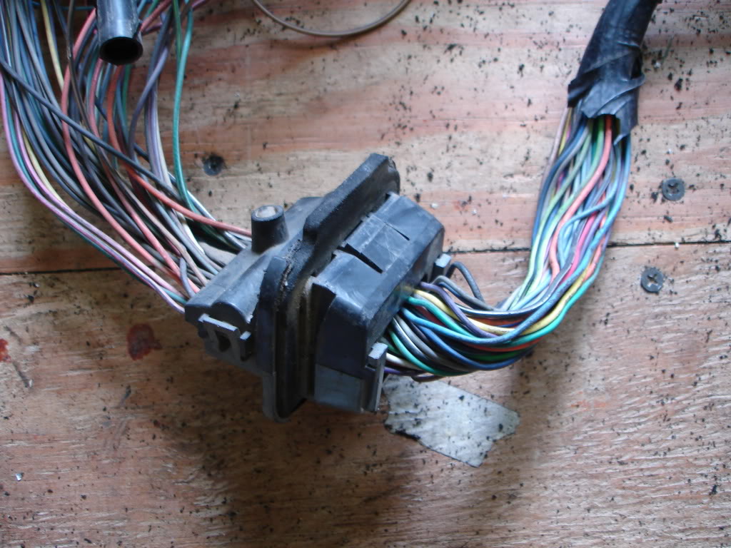
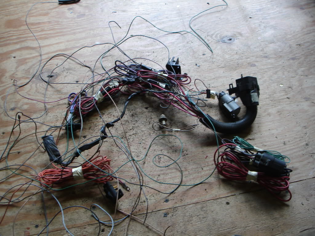
Ok lets get started. This is most of a V6 harness pulled from a 91 camaro. Notice the coil, dist and AC wiring is hacked and in some places missing. Do not fret as none of this is retained
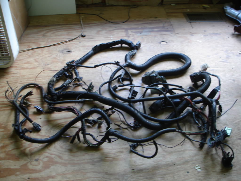
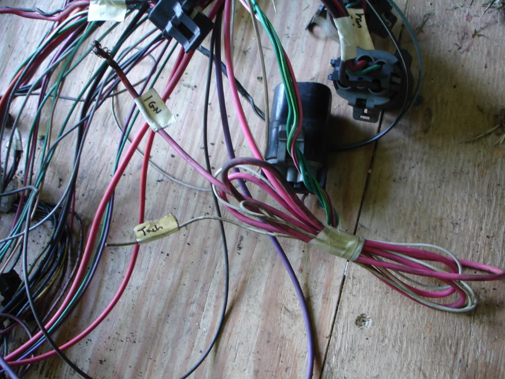
Label all of the connectors you know, namely the ones that are connected to your gauges
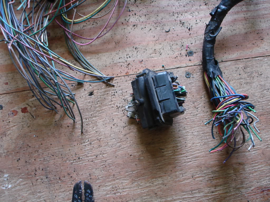
Next strip all of the loom/tape from the harness so you're left with a giant pile of spaghetti
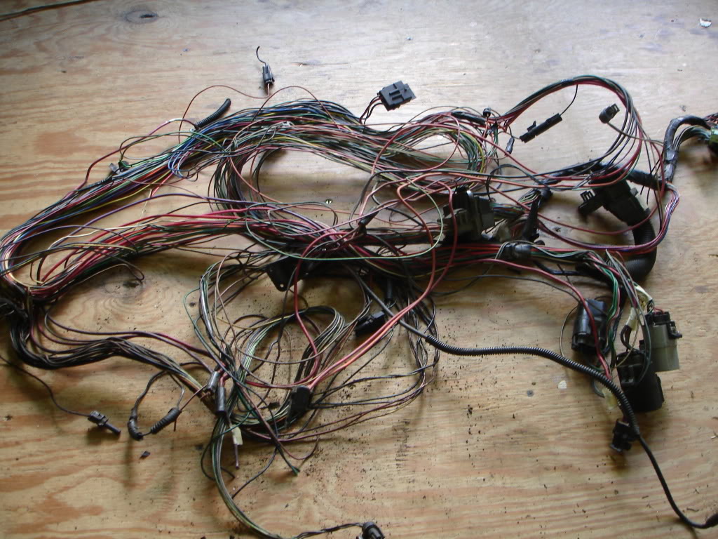
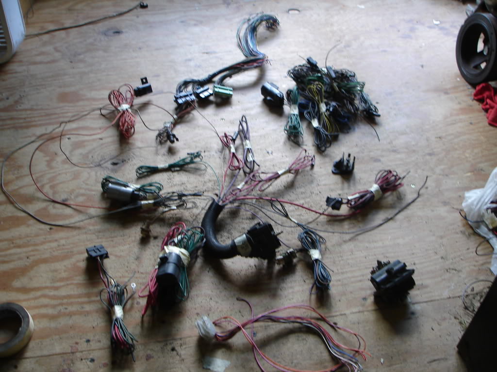
Now start bunching up individual connectors and taping them back so they dont get tangled up so much
All of them dont have to be done, just the more you do the easier the harness will be to separate
Max pics reached
Retaining part of the original harness allows you to keep the stock gauges without rewiring the interior harness. It also makes finding IGN power easy for the new harness
Ok before we begin, Ill get on my soapbox and try to save a bit of money. If you have a 90-92 TPI do not cut the first wire on the harness. Sell it
Buy a V6 or TBI harness and modify that one as they are significantly cheaper and the sale of the SD TPI harness should net you a good chunk back
Everything V6/TBI/TPI about your old harness is being removed
Next lets talk about harness selection. Match the trans type of the harness to the original trans equipped in the car. This will save you tons of headaches with reverse lights, pedal wiring and what-not. Dash harnesses are trans specific and are VERY rarely swapped.
Ok lets get started. This is most of a V6 harness pulled from a 91 camaro. Notice the coil, dist and AC wiring is hacked and in some places missing. Do not fret as none of this is retained
Label all of the connectors you know, namely the ones that are connected to your gauges
Next strip all of the loom/tape from the harness so you're left with a giant pile of spaghetti
Now start bunching up individual connectors and taping them back so they dont get tangled up so much
All of them dont have to be done, just the more you do the easier the harness will be to separate
Max pics reached

The following users liked this post:
bbenson5 (05-26-2023)
09-08-2009, 05:44 PM
#2
Supreme Member
Thread Starter
iTrader: (24)
Join Date: Jun 2005
Location: NC
Posts: 7,890
Likes: 0
Received 59 Likes
on
43 Posts
Car: 92 Firebird
Engine: Supercharged 6.0
Transmission: T56
Axle/Gears: 8.8 3.73
Re: How to prep a 3rd gen harness
Now the cutting starts. Located the fender grommet and cut all of the wires on the front/rear of it. Do not throw this piece away. You can hollow it out and run the new PCM harness thru the existing hole with this connector or put the cut bunch back in place to seal the hole if the PCM is elsewhere
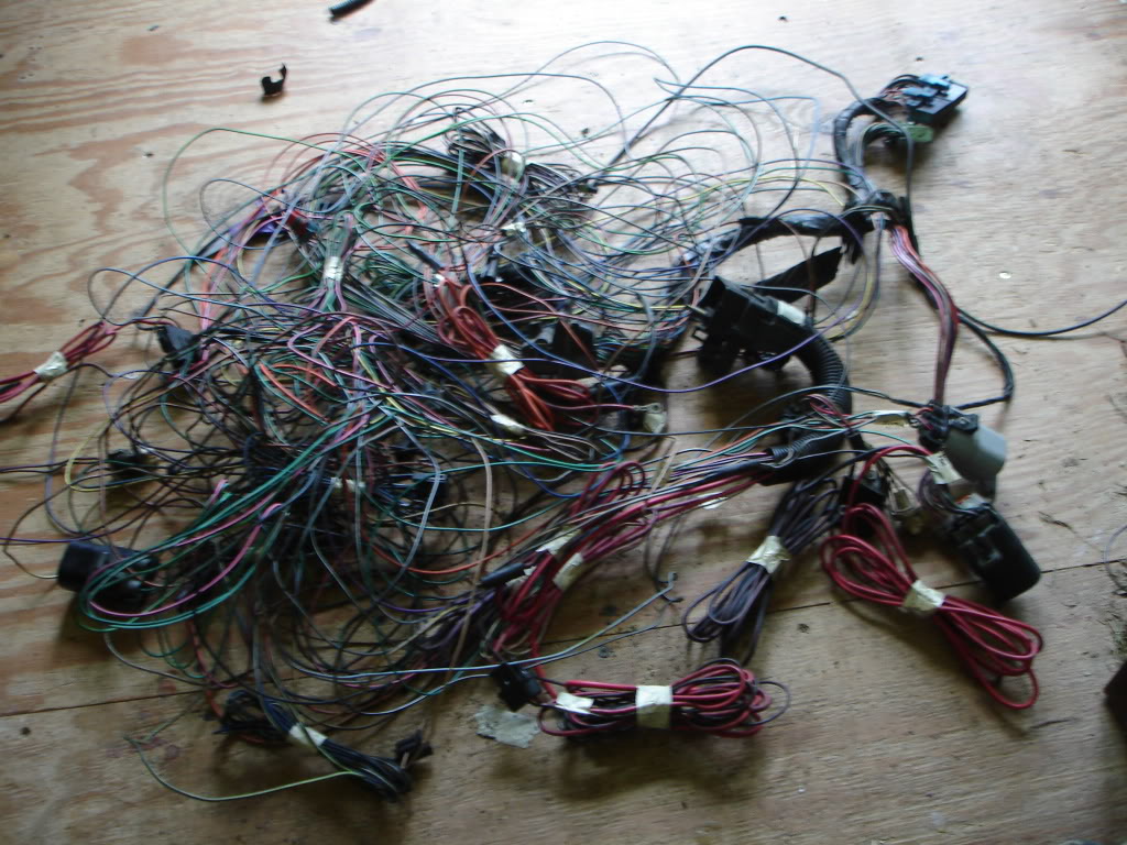
Next cut the C207 connector away from the ECM connectors and put it in the keeper's pile
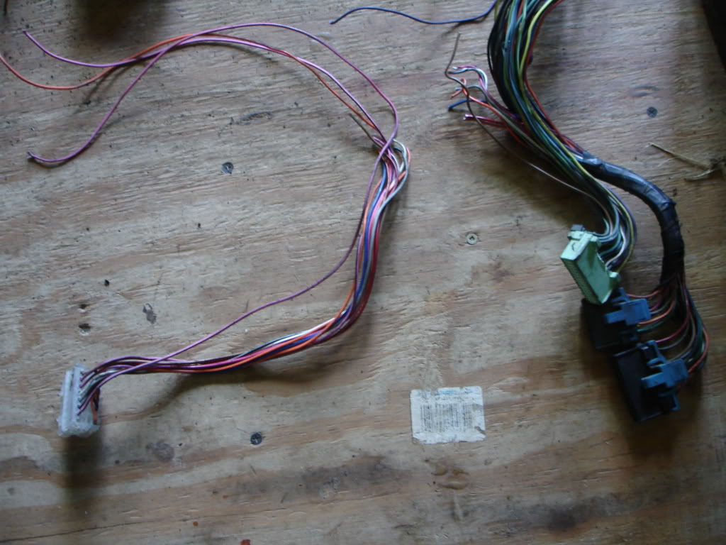
Now rummage thru the spaghetti and cut out any common you find. A common is where multiple wires are spliced from the factory. The usual suspects are grounds, IGN, emissions, AC etc
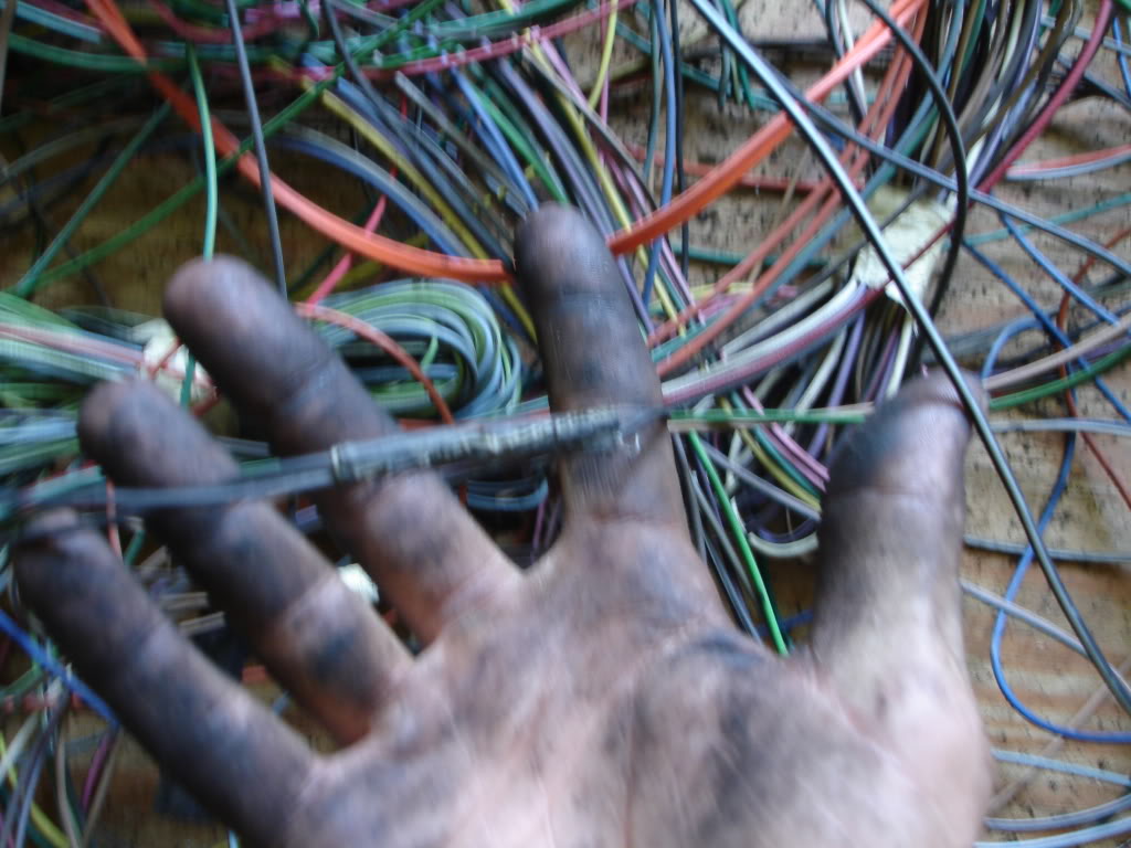
Continue separating the now loose connectors while bunching the still connected ones together
Next cut the C207 connector away from the ECM connectors and put it in the keeper's pile
Now rummage thru the spaghetti and cut out any common you find. A common is where multiple wires are spliced from the factory. The usual suspects are grounds, IGN, emissions, AC etc
Continue separating the now loose connectors while bunching the still connected ones together
The following users liked this post:
bbenson5 (05-26-2023)
09-08-2009, 05:47 PM
#3
Supreme Member
Thread Starter
iTrader: (24)
Join Date: Jun 2005
Location: NC
Posts: 7,890
Likes: 0
Received 59 Likes
on
43 Posts
Car: 92 Firebird
Engine: Supercharged 6.0
Transmission: T56
Axle/Gears: 8.8 3.73
Re: How to prep a 3rd gen harness
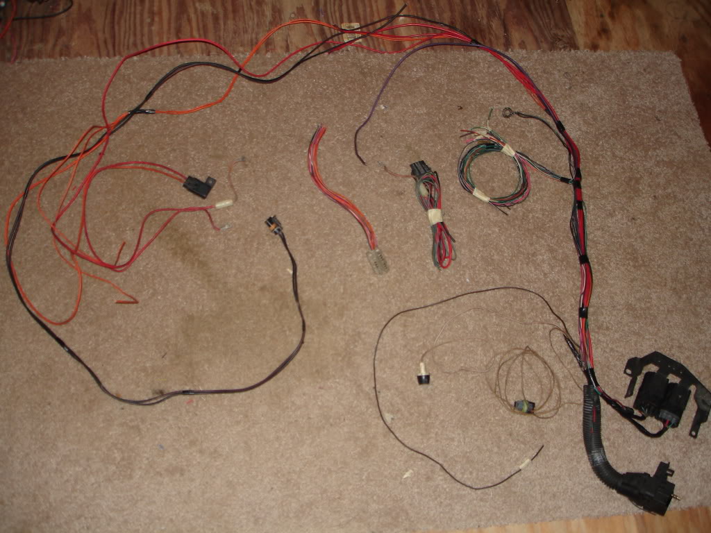
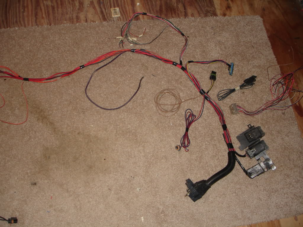
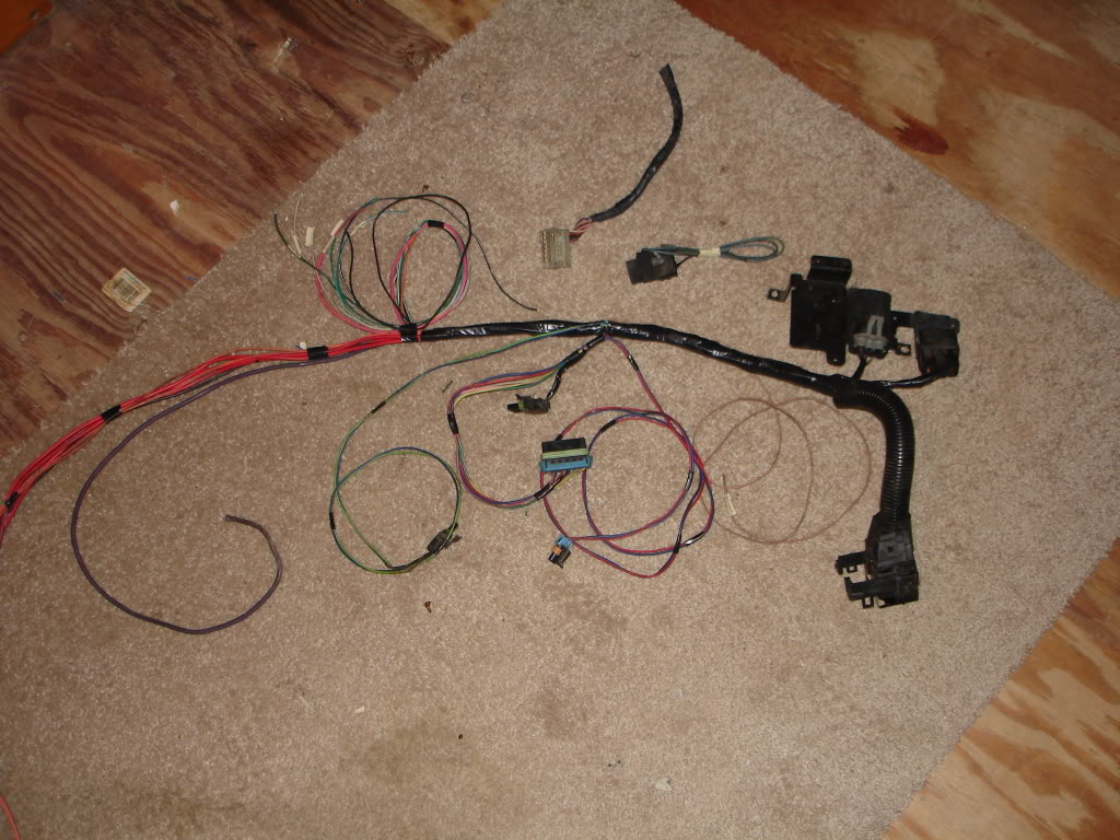
When you are done it should look like this
Starting where the loom ends on the C100
Fan relay and all related wiring. One brown wire should go to the C100 strait to the fan fuse
Brake warning light
Fuel pump relay and related wiring with separate fuse/holder
Coolant gauge
Oil pressure sending unit
Power dist off the starter (can be moved anywhere)
Starter soleniod wire
Emissions common
IGN with tach
Power dist with ALT connector
2x GRD
TCC with plug
Bottom left is the HVAC power connector
Bot middle C207
Bot right fender grommet
Top middle ECM connectors
Top right pile of unneeded engine control connectors. All the V6/TBI/TPI stuff is in here
The job is essentially done. The relays can me moved by lengthening a few wires to anywhere in the engine bay. I do not like the firewall mount so I moved it under the fender for my first swap. My second i found a cute little relay/fuse center from a 98 Cadillac STS
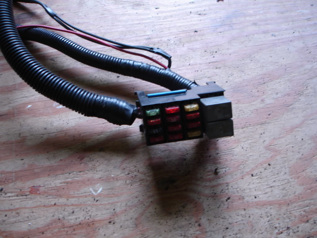
Since it contained enough relays for my swap and ample fuses, I cut out the large 3rd gen relays and wired them into this and mounted it near my battery
Some wires can be removed depending on your selected options
The ALT pigtail can be cutout if using LS1/truck alternator
Both relays can be removed if going mechanical or manually switched
The oil pressure sending unit has 3 wires going to it but only one controls the gauge. GM put a redundant circuit in there to override the fuel pump relay should it fail during driving. While it doesnt matter if its left in there, I usually remove the ORG and GRY wires to simplify the mess
Both power dist wires can be moved off of the starter to a power distribution block mounted anywhere in the engine bay. This cuts down on clutter and speeds troubleshooting when fusible links blow
Emissions common can be removed with no consequence. I opt to retain it since its a fused 12v source perfect for running HO2's
TCC can be removed for manual transmission cars
This is a bare bones setup I use on my race car
This is a 90-92 C100/C207 pinout
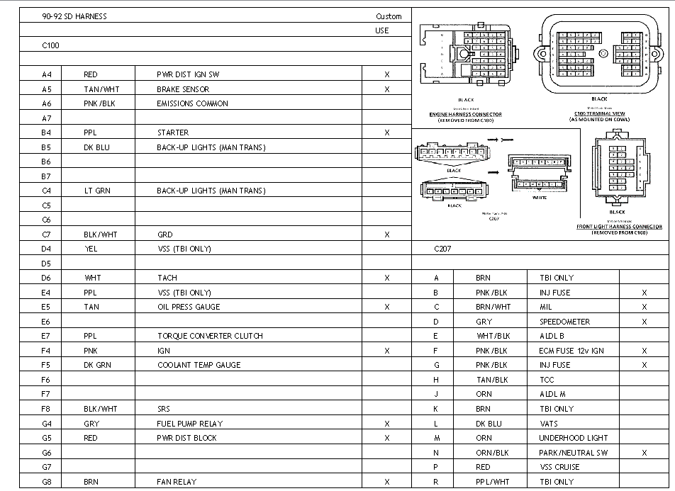
The C207 can be cut down to just 3 wires: speedo, MIL, park/neutral switch
The inj and PCM fuses will have to be moved
For TBI and older cars, you will have a VSS buffer box mounted under your dash. It is there because the PCM cannot understand the raw VSS signal and it must be broken down to something it can read. This is why the TBI cars run the VSS thru the C100 and V6/SD TPI cars run it directly to the ECM
Since the newer LS1/LT1/0411 PCM is quite capable of handling the VSS this box serves no purpose and must be wired around to get your speedo working
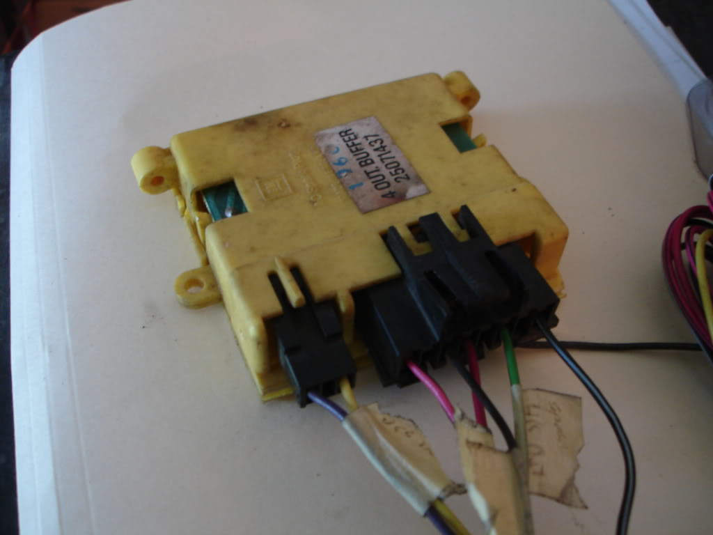
For correct speedo, run the VSS wires directly to the PCM, from there the PCM will output the correct 4,000PPM signal your speedo needs. It should go to pin D in the C207 then be connected to the green wire at the buffer box
Once I get a LS1/truck harness Ill write a how-to-swap it in to take the huge confusion out of most of the threads posted in here
Starting where the loom ends on the C100
Fan relay and all related wiring. One brown wire should go to the C100 strait to the fan fuse
Brake warning light
Fuel pump relay and related wiring with separate fuse/holder
Coolant gauge
Oil pressure sending unit
Power dist off the starter (can be moved anywhere)
Starter soleniod wire
Emissions common
IGN with tach
Power dist with ALT connector
2x GRD
TCC with plug
Bottom left is the HVAC power connector
Bot middle C207
Bot right fender grommet
Top middle ECM connectors
Top right pile of unneeded engine control connectors. All the V6/TBI/TPI stuff is in here
The job is essentially done. The relays can me moved by lengthening a few wires to anywhere in the engine bay. I do not like the firewall mount so I moved it under the fender for my first swap. My second i found a cute little relay/fuse center from a 98 Cadillac STS
Since it contained enough relays for my swap and ample fuses, I cut out the large 3rd gen relays and wired them into this and mounted it near my battery
Some wires can be removed depending on your selected options
The ALT pigtail can be cutout if using LS1/truck alternator
Both relays can be removed if going mechanical or manually switched
The oil pressure sending unit has 3 wires going to it but only one controls the gauge. GM put a redundant circuit in there to override the fuel pump relay should it fail during driving. While it doesnt matter if its left in there, I usually remove the ORG and GRY wires to simplify the mess
Both power dist wires can be moved off of the starter to a power distribution block mounted anywhere in the engine bay. This cuts down on clutter and speeds troubleshooting when fusible links blow
Emissions common can be removed with no consequence. I opt to retain it since its a fused 12v source perfect for running HO2's
TCC can be removed for manual transmission cars
This is a bare bones setup I use on my race car
This is a 90-92 C100/C207 pinout
The C207 can be cut down to just 3 wires: speedo, MIL, park/neutral switch
The inj and PCM fuses will have to be moved
For TBI and older cars, you will have a VSS buffer box mounted under your dash. It is there because the PCM cannot understand the raw VSS signal and it must be broken down to something it can read. This is why the TBI cars run the VSS thru the C100 and V6/SD TPI cars run it directly to the ECM
Since the newer LS1/LT1/0411 PCM is quite capable of handling the VSS this box serves no purpose and must be wired around to get your speedo working
For correct speedo, run the VSS wires directly to the PCM, from there the PCM will output the correct 4,000PPM signal your speedo needs. It should go to pin D in the C207 then be connected to the green wire at the buffer box
Once I get a LS1/truck harness Ill write a how-to-swap it in to take the huge confusion out of most of the threads posted in here
The following users liked this post:
Ethelms (01-18-2023)
09-08-2009, 06:23 PM
#4
Senior Member
iTrader: (3)

Join Date: May 2005
Location: Detroit, MI
Posts: 563
Likes: 0
Received 0 Likes
on
0 Posts
Car: 1991 Z28 Vert
Engine: LT1 350
Transmission: T56 6 Speed
Axle/Gears: 3.42 LSD
Re: How to prep a 3rd gen harness
Good Thread!!! Kinda similar to what I did for my LT1 swap. I had a whole mess of wires.
Jay
Jay
09-08-2009, 06:26 PM
#5
Supreme Member
iTrader: (2)
Join Date: Feb 2006
Location: 39.84N 105.11W
Posts: 1,547
Likes: 0
Received 0 Likes
on
0 Posts
Car: '89 Trans Am GTA
Engine: WAS 350 - now L92 (alum. 378/6.2L)
Transmission: WAS 700R4, now a built T56
Axle/Gears: 3.27 9-bolt
Re: How to prep a 3rd gen harness
GREAT info Pocket, thanks for taking the time to make this thread! 
Mods - I'm thinking that this might just be worth adding to the sticky section...
Mods - I'm thinking that this might just be worth adding to the sticky section...
09-08-2009, 06:42 PM
#6
Supreme Member
iTrader: (30)
Join Date: Sep 2005
Location: O'Fallon, MO
Posts: 6,258
Likes: 0
Received 4 Likes
on
4 Posts
Car: 1991 Z28 convertible built 3/1/1990
Engine: Cammed 6.0L LSX
Transmission: T56
Axle/Gears: custom Ford 8.8", 4.10 gears
Re: How to prep a 3rd gen harness
Hey, my car was an auto but I'm swapping in a T56 if that makes any difference with my wiring harness you and I were talking about.
Trending Topics
09-08-2009, 07:12 PM
#8
Supreme Member
Thread Starter
iTrader: (24)
Join Date: Jun 2005
Location: NC
Posts: 7,890
Likes: 0
Received 59 Likes
on
43 Posts
Car: 92 Firebird
Engine: Supercharged 6.0
Transmission: T56
Axle/Gears: 8.8 3.73
Re: How to prep a 3rd gen harness
Hey, my car was an auto but I'm swapping in a T56 if that makes any difference with my wiring harness you and I were talking about.
I posted about matching your tranny type to harness from the original car because to go manual you have to add pins to the C100. Ive never seen that successfully done short of buying a new C100
09-08-2009, 07:19 PM
#9
Re: How to prep a 3rd gen harness
Nice write up! I think this might be the only thread dedicated to detailing harness work. I know I tried to take pics and make a write up when I did my harness, but I got so involved with it I soon forgot about pics and didnt even really take diligent notes like I intended.
This is GREAT info to help someone get started on their harness!!!
J.
This is GREAT info to help someone get started on their harness!!!
J.
09-08-2009, 08:27 PM
#10
Re: How to prep a 3rd gen harness
like you said about ip harness selection.....use one specific to the tranny u plane to use.
from my exprience, i think there is a bit of qurkiness bw if ur car was orginally carbed or efi.
good thread....wish u had written this earlier.
maybe i am being a baby...can u provide specific details on how u transfered the wires from the ls1 underhood fuse box to that tiny little one.
did u have to cut each wire ends and soder it to the caddilac box or do they just plug in.
09-08-2009, 09:40 PM
#12
Supreme Member
iTrader: (30)
Join Date: Sep 2005
Location: O'Fallon, MO
Posts: 6,258
Likes: 0
Received 4 Likes
on
4 Posts
Car: 1991 Z28 convertible built 3/1/1990
Engine: Cammed 6.0L LSX
Transmission: T56
Axle/Gears: custom Ford 8.8", 4.10 gears
Re: How to prep a 3rd gen harness
So is the harness you have for me from a T5 car or auto, or does it even matter since a T56 isn't a T5? When you say re-pinning the connector, is it just re-soldering the wires into the new positions on the new C100?
09-09-2009, 12:01 AM
#13
Supreme Member
iTrader: (2)
Join Date: Feb 2006
Location: 39.84N 105.11W
Posts: 1,547
Likes: 0
Received 0 Likes
on
0 Posts
Car: '89 Trans Am GTA
Engine: WAS 350 - now L92 (alum. 378/6.2L)
Transmission: WAS 700R4, now a built T56
Axle/Gears: 3.27 9-bolt
Re: How to prep a 3rd gen harness
Originally Posted by Pocket
You will have to update your dash wiring for the new tranny just like any T56 swap
I posted about matching your tranny type to harness from the original car because to go manual you have to add pins to the C100. I've never seen that successfully done short of buying a new C100
I posted about matching your tranny type to harness from the original car because to go manual you have to add pins to the C100. I've never seen that successfully done short of buying a new C100
 Care to elaborate on that?? The only electrical connectors on the transmission are:
the reverse lockout,
the backup light switch,
CAGS

& the VSS output.
In my case, I've read that it won't be necessary to use one of the Dakota Digital boxes with the electronic speedometer in my GTA, as long as the ECM is tuned/programmed correctly - but I'd like to know for sure what you're referring to...
Thanks.
09-09-2009, 08:28 AM
#14
Supreme Member
Thread Starter
iTrader: (24)
Join Date: Jun 2005
Location: NC
Posts: 7,890
Likes: 0
Received 59 Likes
on
43 Posts
Car: 92 Firebird
Engine: Supercharged 6.0
Transmission: T56
Axle/Gears: 8.8 3.73
Re: How to prep a 3rd gen harness
https://www.thirdgen.org/forums/faq-...questions.html
You need to build a new pigtail that runs from the rear of the engine down to the various trans connectors. These are contained in the swap harness, not the original
In addition to moving the connectors around for the new pedals, a few connectors may need to be swapped/added ex. clutch switch
Your auto dash harness will have none of this and using a T5 engine harness will send your backup lights (and VSS for TBI harnesses) to dead ends at the C100
You possibly could cut the C100 wires in question and move them to another pin use on the dash and engine side but in most swaps, ALL C100 pins are retained so you simply dont have any extra pins to move to
Make sense?
09-09-2009, 08:35 AM
#15
Supreme Member
Thread Starter
iTrader: (24)
Join Date: Jun 2005
Location: NC
Posts: 7,890
Likes: 0
Received 59 Likes
on
43 Posts
Car: 92 Firebird
Engine: Supercharged 6.0
Transmission: T56
Axle/Gears: 8.8 3.73
Re: How to prep a 3rd gen harness
https://www.thirdgen.org/forums/tran...-thread-3.html
Post 145 begins the wiring with better pics
One difference i saw was he has a carb car so the ECM is not used. Most swaps reading about this wiring will have some sort of EFI which wants a park/neutral input
From his auto trans connector he leaves two wires off and simply wraps and forgets them. The ORG/BLK is the P/N wire from the PCM. The BLK/WHT is GRD
09-09-2009, 09:28 AM
#16
Supreme Member
iTrader: (2)
Join Date: Feb 2006
Location: 39.84N 105.11W
Posts: 1,547
Likes: 0
Received 0 Likes
on
0 Posts
Car: '89 Trans Am GTA
Engine: WAS 350 - now L92 (alum. 378/6.2L)
Transmission: WAS 700R4, now a built T56
Axle/Gears: 3.27 9-bolt
Re: How to prep a 3rd gen harness
https://www.thirdgen.org/forums/faq-...questions.html
You need to build a new pigtail that runs from the rear of the engine down to the various trans connectors. These are contained in the swap harness, not the original
In addition to moving the connectors around for the new pedals, a few connectors may need to be swapped/added ex. clutch switch
Your auto dash harness will have none of this and using a T5 engine harness will send your backup lights (and VSS for TBI harnesses) to dead ends at the C100
You possibly could cut the C100 wires in question and move them to another pin use on the dash and engine side but in most swaps, ALL C100 pins are retained so you simply dont have any extra pins to move to
Make sense?
You need to build a new pigtail that runs from the rear of the engine down to the various trans connectors. These are contained in the swap harness, not the original
In addition to moving the connectors around for the new pedals, a few connectors may need to be swapped/added ex. clutch switch
Your auto dash harness will have none of this and using a T5 engine harness will send your backup lights (and VSS for TBI harnesses) to dead ends at the C100
You possibly could cut the C100 wires in question and move them to another pin use on the dash and engine side but in most swaps, ALL C100 pins are retained so you simply dont have any extra pins to move to
Make sense?
 Thanks Pocket, I'd forgotten about the clutch switch...
09-09-2009, 09:50 AM
Thanks Pocket, I'd forgotten about the clutch switch...
09-09-2009, 09:50 AM
#17
Supreme Member
Thread Starter
iTrader: (24)
Join Date: Jun 2005
Location: NC
Posts: 7,890
Likes: 0
Received 59 Likes
on
43 Posts
Car: 92 Firebird
Engine: Supercharged 6.0
Transmission: T56
Axle/Gears: 8.8 3.73
Re: How to prep a 3rd gen harness
In my case, I've read that it won't be necessary to use one of the Dakota Digital boxes with the electronic speedometer in my GTA, as long as the ECM is tuned/programmed correctly - but I'd like to know for sure what you're referring to...
All 3rd gen electric speedos that Ive seen require 4,000 PPM input. The best I can tell is LS1s use a 40 pulse per revolution input and change it to 4,000 PPM output to the speedo. The cruise output is 2,000PPM just like 3rd gen cruise
Regardless of older 3rd gens using a 2,000 or 4,000 PPM signal, the value can easily be changed when tuning the LS1 PCM to make what you have work
The dakota box is used to change LT1 T56 11/17 pulse per revolution signal to 2,000/4,000PPM 3rd gen signal when keeping the TPI
09-09-2009, 02:57 PM
#18
09-09-2009, 06:24 PM
#19
Supreme Member
Thread Starter
iTrader: (24)
Join Date: Jun 2005
Location: NC
Posts: 7,890
Likes: 0
Received 59 Likes
on
43 Posts
Car: 92 Firebird
Engine: Supercharged 6.0
Transmission: T56
Axle/Gears: 8.8 3.73
Re: How to prep a 3rd gen harness
Im not using a LS1 fuse box
The Cadillac unit is pretty simple
It has two relays with specific fuses for each as well as extra fuses for whatever else you like
They are simple 4 wire relays. Google relay and youll see how they work
Fuses should be a no brainer
Only 5 are used, 2 for relays, 2 for INJ, one for PCM
The Cadillac unit is pretty simple
It has two relays with specific fuses for each as well as extra fuses for whatever else you like
They are simple 4 wire relays. Google relay and youll see how they work
Fuses should be a no brainer
Only 5 are used, 2 for relays, 2 for INJ, one for PCM
09-10-2009, 06:30 AM
#20
Re: How to prep a 3rd gen harness
What are you running with the two relays? Fuel pump and...? Fans? Do you have the "pink" wire items all running off of the ignition source (big pink wire) or do you have all of that powered from the battery via a relay?
Ide like to knock my fuse boxes down from 2 to 1... I sort of cleaned them up as best I could, but left everything in the stock f-body configuration to get the car running. Tried to avoid wire splices wherever possible.
Still good info in here! Im betting wiring scares a lot of people away from the LS swap...or makes them go carb'd.
J.
09-10-2009, 11:17 AM
#21
Senior Member
Join Date: Aug 2006
Location: Ontario, Canada
Posts: 807
Likes: 0
Received 2 Likes
on
2 Posts
Car: 1991 Trans Am GTA
Engine: LSX (swapping)
Transmission: 4L60E (swapping)
Axle/Gears: 2.73 Posi 10 Bolt
Re: How to prep a 3rd gen harness
Can you elaborate on cutting out the commons Pocket? Where to cut and what to do with the other ends exactly?
09-10-2009, 09:21 PM
#22
Supreme Member
Thread Starter
iTrader: (24)
Join Date: Jun 2005
Location: NC
Posts: 7,890
Likes: 0
Received 59 Likes
on
43 Posts
Car: 92 Firebird
Engine: Supercharged 6.0
Transmission: T56
Axle/Gears: 8.8 3.73
Re: How to prep a 3rd gen harness
What are you running with the two relays? Fuel pump and...? Fans? Do you have the "pink" wire items all running off of the ignition source (big pink wire) or do you have all of that powered from the battery via a relay?
Ide like to knock my fuse boxes down from 2 to 1... I sort of cleaned them up as best I could, but left everything in the stock f-body configuration to get the car running. Tried to avoid wire splices wherever possible.
Still good info in here! Im betting wiring scares a lot of people away from the LS swap...or makes them go carb'd.
J.
Ide like to knock my fuse boxes down from 2 to 1... I sort of cleaned them up as best I could, but left everything in the stock f-body configuration to get the car running. Tried to avoid wire splices wherever possible.
Still good info in here! Im betting wiring scares a lot of people away from the LS swap...or makes them go carb'd.
J.
Everything but the HO2s are off the heavy pink IGN wire from the C100. INJ and PCM pinks are ran thru the mini fuse box. HO2s are off the emissions common
Can you elaborate on cutting out the commons Pocket? Where to cut and what to do with the other ends exactly?
I cut all the wires free just before and just after then discard the common. Most of the wires are either not reused or are rerouted requiring lengthening or trimming to fit with the new harness
In regard to your question about the one closest to the C100, it should be gray and have 3 wires to it. This is the fuel pump common. The relay output goes to the common which goes thru the C100 to the pump itself. This is all you need. The rest can be cut out of the circuit without issue
09-13-2009, 06:31 PM
#23
Senior Member
Join Date: Aug 2006
Location: Ontario, Canada
Posts: 807
Likes: 0
Received 2 Likes
on
2 Posts
Car: 1991 Trans Am GTA
Engine: LSX (swapping)
Transmission: 4L60E (swapping)
Axle/Gears: 2.73 Posi 10 Bolt
Re: How to prep a 3rd gen harness
I think I have gotten myself into a mess lol. I may have to send you some pics so we can go over some things lol.
11-22-2009, 07:14 PM
#25
Supreme Member
Thread Starter
iTrader: (24)
Join Date: Jun 2005
Location: NC
Posts: 7,890
Likes: 0
Received 59 Likes
on
43 Posts
Car: 92 Firebird
Engine: Supercharged 6.0
Transmission: T56
Axle/Gears: 8.8 3.73
Re: How to prep a 3rd gen harness
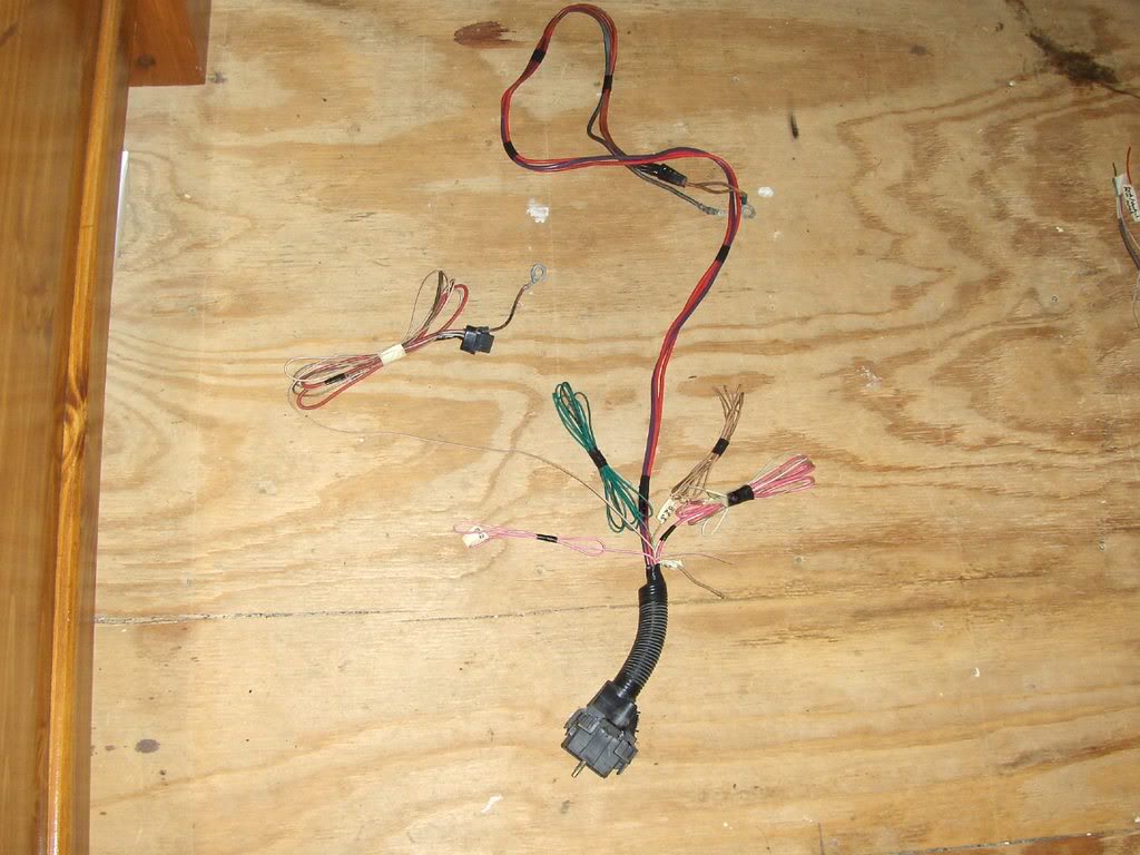
This is what the end result should look like cleaned up and ready to install. The difference between auto and manual is in the rev lights and brake switch. Match your harness to your original trans type
90-92 Auto
Starting lower right and coming around
C100 and relay center. Single fan and fuel pump relay. Dual fan cars will have 3 relays
Brake warning switch
Oil pressure switch
Long brown lead went to the 3rd gen alt. To upgrade to dual fans, splice the brown wire to this lead and run an additional wire to the coil to be connected to the new harness
Coil of leads gets connected to the new harness
Purple starter solenoid wire
Orange and red wires go to the power dist block. The orange wire is connected to an inline fuse holder which powers the PCM constant 12v and fuel pump
End of the trail is the fan connector
The two loose connectors are the HVAC and C207. Non AC swaps simply connect the red to the power dist block and black to ground. AC swaps hook the LT GRN or LT BLU wire to R17 in the swap harness
89 auto
Much the same
Notice the 3 additional connectors for wiper/washer control
The fan fuse is ran through the C207, so that'll have to be lengthened to install this harness
89 manual
Same again except the brake switch wire is missing and the reverse lights connector is present
The three connections regardless of year or swap type(except carb, then no connections are needed)
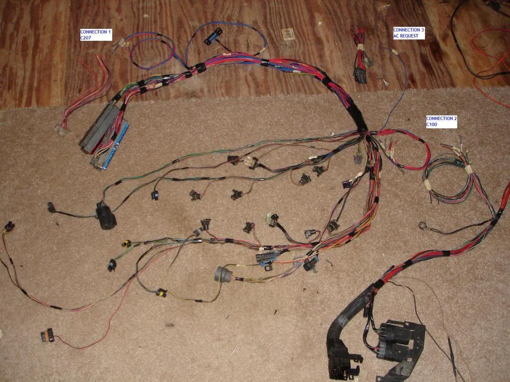
Once these are done, the harness is 100% plug and play as far as engine wiring is concerned
Auto to T56 will require dash wiring modifications for reverse lights, clutch switch and park/neutral. TBI and pre-90 cars with the VSS buffer box will require speedo changes at the buffer connector. All VATS equipped cars will have to bypass the starter relay behind the drivers kick panel. Either connect the two heavy wires or ground the BLK/YEL wire. Grounding the BLK/YEL wire via hidden toggle switch is a good owner anti-theft method
90-92 Auto
Starting lower right and coming around
C100 and relay center. Single fan and fuel pump relay. Dual fan cars will have 3 relays
Brake warning switch
Oil pressure switch
Long brown lead went to the 3rd gen alt. To upgrade to dual fans, splice the brown wire to this lead and run an additional wire to the coil to be connected to the new harness
Coil of leads gets connected to the new harness
Purple starter solenoid wire
Orange and red wires go to the power dist block. The orange wire is connected to an inline fuse holder which powers the PCM constant 12v and fuel pump
End of the trail is the fan connector
The two loose connectors are the HVAC and C207. Non AC swaps simply connect the red to the power dist block and black to ground. AC swaps hook the LT GRN or LT BLU wire to R17 in the swap harness
89 auto
Much the same
Notice the 3 additional connectors for wiper/washer control
The fan fuse is ran through the C207, so that'll have to be lengthened to install this harness
89 manual
Same again except the brake switch wire is missing and the reverse lights connector is present
The three connections regardless of year or swap type(except carb, then no connections are needed)
Once these are done, the harness is 100% plug and play as far as engine wiring is concerned
Auto to T56 will require dash wiring modifications for reverse lights, clutch switch and park/neutral. TBI and pre-90 cars with the VSS buffer box will require speedo changes at the buffer connector. All VATS equipped cars will have to bypass the starter relay behind the drivers kick panel. Either connect the two heavy wires or ground the BLK/YEL wire. Grounding the BLK/YEL wire via hidden toggle switch is a good owner anti-theft method
The following users liked this post:
WOTFBIRD (05-20-2022)
 01-11-2010, 02:12 PM
#27
Junior Member

Join Date: Jan 2005
Posts: 37
Likes: 0
Received 0 Likes
on
0 Posts
Swap Wiring
My Ram Jet 350 came with it's own harness and I will be using aftermarket gauges. I am mainly concerned about non-engine underhood wiring, such as the AC power, Powersteering over pressue switch. How do I deal with these?
01-11-2010, 02:33 PM
#28
Supreme Member
Thread Starter
iTrader: (24)
Join Date: Jun 2005
Location: NC
Posts: 7,890
Likes: 0
Received 59 Likes
on
43 Posts
Car: 92 Firebird
Engine: Supercharged 6.0
Transmission: T56
Axle/Gears: 8.8 3.73
Re: How to prep a 3rd gen harness
AC and PS pressure switches simply bump up the idle when engaged to prevent stalls on the base engines (V6 and TBI). They are part of the EFI harness and will not be reused
01-12-2010, 01:54 PM
#31
Junior Member
Join Date: Jan 2005
Posts: 37
Likes: 0
Received 0 Likes
on
0 Posts
Re: How to prep a 3rd gen harness
What does the HVAC control and where are the two ends of this harness? What does the C207 and C221 do? Where do they connect? My fan has it it's own thermostat, the Ram Jet 350 ECM controls the fuel pump and the BowTie Overdrives 700R4 doesn't use the stock harness (or so I think)
01-18-2010, 07:53 AM
#32
Supreme Member
Thread Starter
iTrader: (24)
Join Date: Jun 2005
Location: NC
Posts: 7,890
Likes: 0
Received 59 Likes
on
43 Posts
Car: 92 Firebird
Engine: Supercharged 6.0
Transmission: T56
Axle/Gears: 8.8 3.73
Re: How to prep a 3rd gen harness
Heating Ventilation Air Conditioning
When you turn the AC on, it sends 12v to engage the compressor clutch. It also sends a 12v reference back to the ECM to let it know AC is engaged and functioning. The ECM sees this is a additional draw on the engine and will bump up the idle speed to prevent stalling. If the new ECM does not have a AC request wire, this wire is ignored and you must manually watch the tach at idle with the AC on much like older carbed cars did
As listed above, the C207 houses many of the critical wires that controls both fuses and gauges. It is the clear connector near the ECM. The dash side has two black halves. It is often wrapped in adhesive foam. Pre 89 cars run the fuel pump wire through this as well
The C221 is only found on pre 89 Fbodys. It houses the Fan relay fuse and injectors fuse wires
If you are using a temp switch (looks like a knock sensors in the cyl head) then the ECM doesnt need to control your fans. The sensor does it for you. Be sure to wire it on the ground side of the fan relay
Why would the BTO control the trans instead of your ECM harness? BTO uses vacuum solneoids or manual switches to control lockup. The ECM uses multiple circumstances to electronically engage lockup, namely speed, gear and RPM. Im unfamiliar with RAMJets ECM, but it would be silly for GM to release a trans that is incapable of controlling the 700R4 and 200R4, arguably the two MOST popular overdrive GM transmissions for non stock cars
01-23-2010, 08:35 AM
#33
Member
Re: How to prep a 3rd gen harness
Does the VATS need to be addressed at this time? Mine has been bypassed already due to steering column/ignition replacement.
I'm thinking I got lucky in that my LT1 setup came in a running car, and therefore, with a chipped key.
I'm thinking I got lucky in that my LT1 setup came in a running car, and therefore, with a chipped key.
01-23-2010, 09:09 AM
#34
Supreme Member
Thread Starter
iTrader: (24)
Join Date: Jun 2005
Location: NC
Posts: 7,890
Likes: 0
Received 59 Likes
on
43 Posts
Car: 92 Firebird
Engine: Supercharged 6.0
Transmission: T56
Axle/Gears: 8.8 3.73
Re: How to prep a 3rd gen harness
Short of every wire in the donor car along with the donor's steering column/key, VATS must be disabled in the LT1 PCM
The 3rd gen VATS seems to be hit or miss. The only aspect of it remaining is the starter relay and how to bypass it is posted. An alternative would be the resistor bypass. Some folks just luck out and the 3rd gen VATS is just fine with the new PCM, even though it doesnt have the fuel/IGN kill it used to. Others require it to be bypassed
The 3rd gen VATS seems to be hit or miss. The only aspect of it remaining is the starter relay and how to bypass it is posted. An alternative would be the resistor bypass. Some folks just luck out and the 3rd gen VATS is just fine with the new PCM, even though it doesnt have the fuel/IGN kill it used to. Others require it to be bypassed
01-23-2010, 09:44 AM
#35
Member
Re: How to prep a 3rd gen harness
I actually have the resistor bypass already in place, I think I just misunderstood how the resisitance values are read. It was my understanding that the resistance value required was stored in the PCM.
regardless, great info thanks again. Can't wait to see that 305 land very hard onto a scrap pile.
regardless, great info thanks again. Can't wait to see that 305 land very hard onto a scrap pile.
01-23-2010, 09:52 AM
#36
Supreme Member
Thread Starter
iTrader: (24)
Join Date: Jun 2005
Location: NC
Posts: 7,890
Likes: 0
Received 59 Likes
on
43 Posts
Car: 92 Firebird
Engine: Supercharged 6.0
Transmission: T56
Axle/Gears: 8.8 3.73
Re: How to prep a 3rd gen harness
3rd gens have a VATS module under the dash. When the correct key is inserted, it send the correct signals to the ECM to allow the engine to run
02-15-2010, 04:22 PM
#37
Member
iTrader: (3)
Join Date: Feb 2007
Location: CT
Posts: 232
Likes: 0
Received 0 Likes
on
0 Posts
Car: 1992 RS
Engine: 01' LS1
Transmission: T56
Axle/Gears: 10 bolt auburn pro posi, 4.10 gears
Re: How to prep a 3rd gen harness
excellent write up. i will be using this when i start wiring my ls1/t56 build
05-05-2010, 10:53 PM
#38
Supreme Member
iTrader: (1)
Join Date: Mar 2007
Location: Arlington, Tx
Posts: 3,525
Likes: 0
Received 6 Likes
on
5 Posts
Car: 91 Camaro RS
Engine: empty bay (for now)
Transmission: Built T-56
Axle/Gears: 3.42 stock posi disc
Re: How to prep a 3rd gen harness
Can we make this a sticky? Over the past month I think I've sent about 15 people to this thread for engine wiring help.
05-06-2010, 04:23 PM
#39
Supreme Member
Thread Starter
iTrader: (24)
Join Date: Jun 2005
Location: NC
Posts: 7,890
Likes: 0
Received 59 Likes
on
43 Posts
Car: 92 Firebird
Engine: Supercharged 6.0
Transmission: T56
Axle/Gears: 8.8 3.73
Re: How to prep a 3rd gen harness
Its in the LSx and LTx swap stickies. Only other place it should go is the carb forum
05-15-2010, 09:18 PM
#40
Supreme Member
iTrader: (1)
Join Date: Mar 2007
Location: Arlington, Tx
Posts: 3,525
Likes: 0
Received 6 Likes
on
5 Posts
Car: 91 Camaro RS
Engine: empty bay (for now)
Transmission: Built T-56
Axle/Gears: 3.42 stock posi disc
Re: How to prep a 3rd gen harness
Im never really in the LSx/LTx forum so I guess thats why I didnt see it. Maybe it sould be in the general engine swap forum since it doesnt just apply to LSx/LTx swaps
05-19-2010, 08:34 PM
#41
Member
iTrader: (1)
Join Date: May 2010
Location: Chickamauga, GA
Posts: 426
Likes: 0
Received 0 Likes
on
0 Posts
Car: 89 IROC-Z
Engine: 355ci SBC
Transmission: TH700R4 - 2500 stall
Axle/Gears: 3.70 9 bolt
Re: How to prep a 3rd gen harness
So, correct me if I'm wrong but on the harness coming out of the drivers side there are two plugs. One is the front headlight connector and the other holds all the essential wiring needed for my LS1 swap. My car is a 91 Trans Am with the TPI 305 and automatic. My question is, the red and white wires that go to the coil. The white is for my Tach correct? And where would the red wire go on the LS1 harness? Also that 4 pin plug that went to the automatic trans, can I get rid of it or do I need that purple wire? I think I'm tracking just wanted to make sure.
Also inside the car when I took the ECM out there was a plug that went across the dash from the computer harness. What on earth goes there? Anything I should be concerned with? I'm using a painless harness btw. Thanks!
Also inside the car when I took the ECM out there was a plug that went across the dash from the computer harness. What on earth goes there? Anything I should be concerned with? I'm using a painless harness btw. Thanks!
05-19-2010, 09:20 PM
#42
Supreme Member
Thread Starter
iTrader: (24)
Join Date: Jun 2005
Location: NC
Posts: 7,890
Likes: 0
Received 59 Likes
on
43 Posts
Car: 92 Firebird
Engine: Supercharged 6.0
Transmission: T56
Axle/Gears: 8.8 3.73
Re: How to prep a 3rd gen harness
91 TPI would be a SD TPI harness. You should sell it
Old coil connector should have a heavy pink and small white. Heavy pink is the main IGN wire from the IGN switch
White is tach
PPL wire from the old TCC connector is the brake switch. It goes to B33 for 99-04 LS1 PCMs
The under dash connector should be clear. Its the C207 and contains the majority of your fuses along with the speedo and MIL wires
If the painless is a stand along harness, then the fuse wires are ignored. Several connections are still necessary at that connector though
08-08-2010, 09:58 AM
#43
Senior Member

Join Date: Sep 2007
Location: Long Island, NY
Posts: 599
Likes: 0
Received 1 Like
on
1 Post
Car: 1992 z28
Engine: 383 LT1 in the works
Transmission: T-56 in the works
Axle/Gears: 3.73 in the works
Re: How to prep a 3rd gen harness
Pocket - still not sure what to do with the C207 for the LT1 swap. The C100 is all hooked up to my stand alone lt1 harness with exception to the brown wire for the fans. No idea what to do with that. Anyone know?
Then for the C207 how does this get hooked up? there are a dozen or so wires and the helm manual isnt much help for identifying the wiring for this.
I am using all new autometer gauges so do I wire all of these into the C207 (clear white connector side)? or something elsE?
What have you guys done? This is the last thing i need. Thanks
08-08-2010, 11:31 AM
#44
Supreme Member
Thread Starter
iTrader: (24)
Join Date: Jun 2005
Location: NC
Posts: 7,890
Likes: 0
Received 59 Likes
on
43 Posts
Car: 92 Firebird
Engine: Supercharged 6.0
Transmission: T56
Axle/Gears: 8.8 3.73
Re: How to prep a 3rd gen harness
If the brn fan wire is the fused leg, then hook it to the alt wire in the C100. 3rd gens put the fan relay fuse and alt fuse in the same spot for some reason
With a stand alone, the C207 is mostly empty save a few gauge wires. The stand alone will have INJ1, INJ2, PCM IGN fuses already so pins B, F, G will be skipped
You need to attach the PCM speedo output signal to pin D (gry V6/TPI) or pin K (brn TBI with buffer box bypass). PCM MIL signal (brn/wht) to pin C and the ALDL wires if the connector is not already included. The P/Neutral wire is recommended for 4L60E swaps to improve idle quality. It is also a direct output from the PCM
08-13-2010, 04:49 PM
#45
Senior Member
Join Date: Sep 2007
Location: Long Island, NY
Posts: 599
Likes: 0
Received 1 Like
on
1 Post
Car: 1992 z28
Engine: 383 LT1 in the works
Transmission: T-56 in the works
Axle/Gears: 3.73 in the works
Re: How to prep a 3rd gen harness
If the brn fan wire is the fused leg, then hook it to the alt wire in the C100. 3rd gens put the fan relay fuse and alt fuse in the same spot for some reason
With a stand alone, the C207 is mostly empty save a few gauge wires. The stand alone will have INJ1, INJ2, PCM IGN fuses already so pins B, F, G will be skipped
You need to attach the PCM speedo output signal to pin D (gry V6/TPI) or pin K (brn TBI with buffer box bypass). PCM MIL signal (brn/wht) to pin C and the ALDL wires if the connector is not already included. The P/Neutral wire is recommended for 4L60E swaps to improve idle quality. It is also a direct output from the PCM
With a stand alone, the C207 is mostly empty save a few gauge wires. The stand alone will have INJ1, INJ2, PCM IGN fuses already so pins B, F, G will be skipped
You need to attach the PCM speedo output signal to pin D (gry V6/TPI) or pin K (brn TBI with buffer box bypass). PCM MIL signal (brn/wht) to pin C and the ALDL wires if the connector is not already included. The P/Neutral wire is recommended for 4L60E swaps to improve idle quality. It is also a direct output from the PCM
So am i only connecting two wires to the C207 then? I have a T56 so dont need to wire for 4L60E like you said. There is also a green A/C clutch wire from the stand alone harness but i have no AC so that will just get tucked away then.
the LAST wire i will have left then is the brown coolant fan relay wire which you said goes into the alt wire of the C100. which is the alternator wire? i think that was removed when i took apart the harness OR is it the heavy gauge purple wire that is for "charging system" ?
08-30-2010, 04:24 PM
#46
Senior Member
Join Date: Sep 2007
Location: Long Island, NY
Posts: 599
Likes: 0
Received 1 Like
on
1 Post
Car: 1992 z28
Engine: 383 LT1 in the works
Transmission: T-56 in the works
Axle/Gears: 3.73 in the works
Re: How to prep a 3rd gen harness
Pocket - what does this brown wire from the C100 do? do I need to hook it up? my stand alone harness has the relays and all wiring to hook up to the fans and is controlled by computer. I dont see how there is any relation between the stand along setup and this brown wire for fan relay from the C100.
im not sure how to go about to check if this thing is fused or not. i'll have to pull out the C100 from the car and check the wiring diagrams to see whats on the interior side and then see if that goes to a fuse? if it does you say to go into the alt wire of the C100... i have no alternator wire on the engine side so how would i connect this?
my stand alone harness does not have a connector for the alternator. i dont think i need one right? the battery hooks up to it and thats it?
08-30-2010, 10:05 PM
#47
Supreme Member
Thread Starter
iTrader: (24)
Join Date: Jun 2005
Location: NC
Posts: 7,890
Likes: 0
Received 59 Likes
on
43 Posts
Car: 92 Firebird
Engine: Supercharged 6.0
Transmission: T56
Axle/Gears: 8.8 3.73
Re: How to prep a 3rd gen harness
Stand alone doesnt require it, thats the point of it being stand alone
To see if it's fused (and it is) flick the IGn switch on and check for 12v. Now pull the fan fuse and check for 12v. It should be gone now
Is there an alt connector wired into the harness? LTx harnesses use the resistor wire on a 12v IGN source, LSx are controlled by the PCM. Neither should have a direct fuse in the stand alone harness. It should be integrated unless its a crappy harness and no connector was supplied
08-31-2010, 08:02 AM
#48
Senior Member
Join Date: Sep 2007
Location: Long Island, NY
Posts: 599
Likes: 0
Received 1 Like
on
1 Post
Car: 1992 z28
Engine: 383 LT1 in the works
Transmission: T-56 in the works
Axle/Gears: 3.73 in the works
Re: How to prep a 3rd gen harness
hmm... then i guess i have a crappy harness lol because i dont have any connector for the alternator. Soo now what can i do about this? im also using an after market alternator not a factory LT1 because i relocated the alt mount to low passenger side which required a specific GM alternator, I dont have the number now but i can get it if i need to.
my battery and all the interior is not completely hooked up yet so i cant test the brn wire for 12v with ign on but i trust you.
wish you were closer so i can atleast get you a case of beer or something for all the help you are providing. i'd never get this car done without your help. after this is all said and done i think i will put together a write up for using stand alone harnesses.
lol because i dont have any connector for the alternator. Soo now what can i do about this? im also using an after market alternator not a factory LT1 because i relocated the alt mount to low passenger side which required a specific GM alternator, I dont have the number now but i can get it if i need to.my battery and all the interior is not completely hooked up yet so i cant test the brn wire for 12v with ign on but i trust you.
wish you were closer so i can atleast get you a case of beer or something for all the help you are providing. i'd never get this car done without your help. after this is all said and done i think i will put together a write up for using stand alone harnesses.
08-31-2010, 08:30 AM
#49
Supreme Member
Thread Starter
iTrader: (24)
Join Date: Jun 2005
Location: NC
Posts: 7,890
Likes: 0
Received 59 Likes
on
43 Posts
Car: 92 Firebird
Engine: Supercharged 6.0
Transmission: T56
Axle/Gears: 8.8 3.73
Re: How to prep a 3rd gen harness
Several low end companies cut corners by building a harness with only the absolute necessary connectors for the engine control. Trans, accys, relays etc are an added cost. I see this frequently with the $350 LS1 ebay harnesses
Dont fret about it, since you changed alt type the stock connector wouldnt be much help unless it lucked out matching up exactly. Now, what vehicles did the alt come on originally? Id find one in the yard and snip the connector free. Its either a 1 wire, 2 wire, or 3 wire alt, so figuring out which goes where is the next job. Most require 12v battery (large wire), 12v fused IGN (small wire) and/or the dummy light wire that needs the voltage knocked down from 12v with a resistor or in line light bulb (small wire)
EX: 3rd gens use the battery wire and fuse wire
Early LT1s used the fuse wire and dummy light, laters the dummy light only
LS1s used a PCM controlled dummy light wire
Trucks and later LSx used the fuse wire and dummy light
08-31-2010, 09:39 AM
#50
Senior Member
Join Date: Sep 2007
Location: Long Island, NY
Posts: 599
Likes: 0
Received 1 Like
on
1 Post
Car: 1992 z28
Engine: 383 LT1 in the works
Transmission: T-56 in the works
Axle/Gears: 3.73 in the works
Re: How to prep a 3rd gen harness
Several low end companies cut corners by building a harness with only the absolute necessary connectors for the engine control. Trans, accys, relays etc are an added cost. I see this frequently with the $350 LS1 ebay harnesses
Dont fret about it, since you changed alt type the stock connector wouldnt be much help unless it lucked out matching up exactly. Now, what vehicles did the alt come on originally? Id find one in the yard and snip the connector free. Its either a 1 wire, 2 wire, or 3 wire alt, so figuring out which goes where is the next job. Most require 12v battery (large wire), 12v fused IGN (small wire) and/or the dummy light wire that needs the voltage knocked down from 12v with a resistor or in line light bulb (small wire)
EX: 3rd gens use the battery wire and fuse wire
Early LT1s used the fuse wire and dummy light, laters the dummy light only
LS1s used a PCM controlled dummy light wire
Trucks and later LSx used the fuse wire and dummy light
Dont fret about it, since you changed alt type the stock connector wouldnt be much help unless it lucked out matching up exactly. Now, what vehicles did the alt come on originally? Id find one in the yard and snip the connector free. Its either a 1 wire, 2 wire, or 3 wire alt, so figuring out which goes where is the next job. Most require 12v battery (large wire), 12v fused IGN (small wire) and/or the dummy light wire that needs the voltage knocked down from 12v with a resistor or in line light bulb (small wire)
EX: 3rd gens use the battery wire and fuse wire
Early LT1s used the fuse wire and dummy light, laters the dummy light only
LS1s used a PCM controlled dummy light wire
Trucks and later LSx used the fuse wire and dummy light
I'll be home early this afternoon and will check up on this. I will have the large ga wire from the battery to the alt and also the purple wire from the thirdgen C100 (engine side) goes to the alternator too. Would this be enough? Or would i keep those two and then also go for the dummy light wire (what does this wire do and what is it?)