No ECM TCC Lockup Diagram
 07-15-2012, 11:13 PM
#1
Senior Member

Thread Starter
Join Date: Sep 2006
Location: San Antonio, Tx
Posts: 568
Likes: 0
Received 7 Likes
on
6 Posts
Car: 1988 Camaro IROC-Z
Engine: LB9 (305 TPI)
Transmission: 700R4
Axle/Gears: 2.73 Positraction
No ECM TCC Lockup Diagram
I'm running an aftermarket ECM that doesn't control TCC Lockup, and after searching the various diagrams available online developed my own wiring circuit that allows for both normal 4th gear only TCC lockup, as well as manual 2, 3, 4 TCC lockup control. This is also useful for those who have switched to a carb setup on a previously ECM controlled car, or have installed a later model computer lockup-controlled 700R4 / 4L60 into an earlier model car. The benefits to my circuit are that is much simpler than most of the other solutions I have seen, uses a simple SPST (ON / OFF) switch instead of a 3-position DPDT switch, it allows easy troubleshooting of the TCC lockup circuit, and it won't cost you anywhere near what the aftermarket kits will.
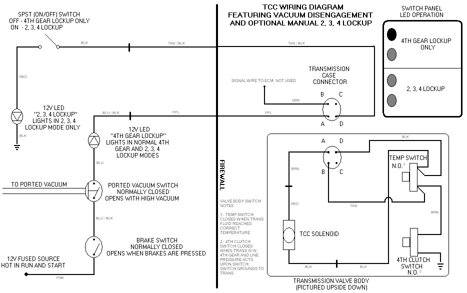
The normal "4TH GEAR ONLY" TCC lockup circuit path flows from a 12V fused Hot In Run and Start source (usually a pink wire in GM applications), flows thru the normally closed brake switch (opens when brakes are applied to disengage TCC lockup when braking or coming to a stop), then thru a normally closed ported vacuum switch (opens when vacuum rises to disengage TCC lockup for passing / WOT. Ported vacuum is preferred, and a switch can be sourced from an early 80's full size carb'ed Chevy truck. Manifold vacuum can be used, but you may need an adjustable normally closed vacuum switch to properly work). The circuit then passes thru a 12V LED with built in resistor to indicate when the normal 4th gear lockup circuit has a complete path to ground, and then to the "A" port on the transmission case connector. This is the 12V feed wire to the TCC solenoid. The circuit continues on in normal 4th gear only mode to the trans temp switch, which closes when the trans fluid reaches the correct temperature and allows the switch to close. The circuit then flows to the 4th clutch switch, which is closed by fluid pressure in the valve body when the trans shifts to 4th gear. The 4th clutch switch grounds to the valve body and transmission, completing the circuit.
The alternate "MANUAL 2, 3, 4" TCC lockup circuit is identical to the first part of the "4TH GEAR ONLY" TCC lockup path, but flows from negative side of the TCC solenoid to the "D" port on the transmission case connector by way of a jumper at the feed terminal of the trans temp switch. This provides an alternate ground path for the TCC solenoid that bypasses both the trans temp switch and the 4th clutch switch. The circuit flows out of the trans and to a SPST ON/OFF switch mounted in the cabin, which in the normal 4th gear TCC lockup only mode is left in the OFF position. This opens the circuit path and forces the circuit to complete thru the trans temp switch and 4th clutch switch to reach ground. When the SPST switch is ON, the circuit closes and flows to a second 12V LED with resistor, then finally to ground. This second LED lights along with the 4th gear lockup LED in the manual 2, 3, 4 TCC lockup mode. Note that the wire from the "C" terminal of the transmission case connector (normally used to send a signal to the ECM that the trans is in lockup) is not used.
The benefit of this is arrangement is that it allows for a TCC circuit test any time the ignition is on. For example: If both LEDs light when the switch is in the ON (manual 2, 3, 4 lockup) position, then the TCC circuit has a good flow path thru the brake switch, vacuum switch, both LEDs, and the TCC solenoid to ground (TCC solenoid operation can be verified audibly by listening for a "click" from the transmission pan when the SPST switch is flipped to the ON position). If you are not getting lockup in normal 4th gear only mode when the SPST switch is in the OFF mode and the first LED does not light, but you get lockup and both LED's light when the SPST switch is in the ON mode, then you know you either have a faulty trans temp switch or 4th clutch switch. If you are not getting lockup in either mode, the first LED does not light when the SPST switch is OFF, but both LEDs light when the SPST switch is ON, then you most likely have a line pressure, fluid problem, or a converter problem. This could also be due to a shorted TCC solenoid, but again can be checked audibly. If you are not getting lockup in either mode, and neither LED is lighting, then you have a problem in the TCC circuit such as the brake switch, vacuum switch, or TCC solenoid.
Note: If a third option of no TCC lockup is wanted, a second SPST ON/OFF switch could be added to the circuit anywhere ahead of the first LED. This would open the circuit in the OFF mode, cutting off 12V supply from reaching the TCC solenoid and preventing lockup.
The wire colors are for my specific application (1988 Chevrolet IROC-Z LB9 700R4/4L60), so they may vary in your setup. If anyone has questions about my circuit, or needs a higher quality file copy of it, feel free to PM me.
 07-16-2012, 02:00 AM
#2
Supreme Member

Join Date: Jun 2005
Location: Sydney, Australia
Posts: 1,380
Likes: 0
Received 5 Likes
on
5 Posts
Car: '86 TA
Engine: '74 350
Transmission: 700r4
Axle/Gears: 2.77
Re: No ECM TCC Lockup Diagram
Good write-up. There's been a few similar diagrams posted here over the years; I did something similar to yours myself, but used the dash 'Shift' light as the indicator.
The simplest idea I found posted, was to remove ecm, keep the factory wiring, and just connect the new vacuum switch across terminals B & D of the tranny connector. This retains the stock brake and 4th gear switches, but doesn't give you any indicators or 2-3-4 (if that's what you want)
Just a question about the led placement - it's got a current limit resistor as generally required by leds. You've got it in series with the tcc solenoid, limiting current to that as well, which requires a few amps iirc. Does the solenoid still pull in reliably?
07-16-2012, 10:39 AM
#3
Senior Member
Thread Starter
Join Date: Sep 2006
Location: San Antonio, Tx
Posts: 568
Likes: 0
Received 7 Likes
on
6 Posts
Car: 1988 Camaro IROC-Z
Engine: LB9 (305 TPI)
Transmission: 700R4
Axle/Gears: 2.73 Positraction
Re: No ECM TCC Lockup Diagram
It seems to with the car off, when it's only getting about 10.25V. With the car running it gets a little over 12V, as the alternator steps up the available voltage to closer to 14V. I was worried about the drop in current as well, but the drop is minimal, and the solenoid does "click" audibly in the pan.
07-29-2012, 12:03 AM
#4
Senior Member
Thread Starter
Join Date: Sep 2006
Location: San Antonio, Tx
Posts: 568
Likes: 0
Received 7 Likes
on
6 Posts
Car: 1988 Camaro IROC-Z
Engine: LB9 (305 TPI)
Transmission: 700R4
Axle/Gears: 2.73 Positraction
Re: No ECM TCC Lockup Diagram
**UPDATE**
I was having problems getting lockup in normal mode, with the "4th Gear Only" LED not lighting in "Normal" mode, but both LEDs lighting in "2, 3, 4" mode. I drained and dropped my pan and tested the circuit, finding that the 12V LEDs I had selected with built in resistors were dropping the current too much (Thanks TreeFiddy!). I removed both LEDs from the circuit, and verified solenoid function with the pan still off. The TCC solenoid tested sucessfully in "2, 3, 4" mode with the SPST switch in the "On" position, and after refilling the trans and test driving has proper lockup in both "Normal" and "2, 3, 4" modes. The converter locks in 4th gear around 40-45 mph, disengaging if the brakes are pressed or if the vacuum switch senses low vacuum. Light throttle input does not cause TCC disengagement in either "Normal" or "2, 3, 4" mode. The only downside is I have no LED confirmation of circuit completion as of yet, until I find an LED rated for 12V that will not draw too much current. My modified diagram is below, and is road tested and functional.
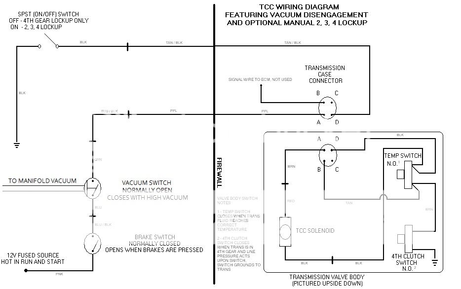
I also changed to a normally open vacuum switch as these are far more available in junkyards. Look on the driver side firewall of early 80's full size Chevy trucks. Be sure to grab the pigtail as well, and enough wire length. This also necessitated a change to a manifold vacuum source instead of ported vacuum, as I needed a vacuum source that is fairly constant except in WOT conditions. Either setup will work, but it is important to use the right vacuum; Normally closed vacuum switch uses a ported source, normally open vacuum switch uses a manifold source.
I was having problems getting lockup in normal mode, with the "4th Gear Only" LED not lighting in "Normal" mode, but both LEDs lighting in "2, 3, 4" mode. I drained and dropped my pan and tested the circuit, finding that the 12V LEDs I had selected with built in resistors were dropping the current too much (Thanks TreeFiddy!). I removed both LEDs from the circuit, and verified solenoid function with the pan still off. The TCC solenoid tested sucessfully in "2, 3, 4" mode with the SPST switch in the "On" position, and after refilling the trans and test driving has proper lockup in both "Normal" and "2, 3, 4" modes. The converter locks in 4th gear around 40-45 mph, disengaging if the brakes are pressed or if the vacuum switch senses low vacuum. Light throttle input does not cause TCC disengagement in either "Normal" or "2, 3, 4" mode. The only downside is I have no LED confirmation of circuit completion as of yet, until I find an LED rated for 12V that will not draw too much current. My modified diagram is below, and is road tested and functional.
I also changed to a normally open vacuum switch as these are far more available in junkyards. Look on the driver side firewall of early 80's full size Chevy trucks. Be sure to grab the pigtail as well, and enough wire length. This also necessitated a change to a manifold vacuum source instead of ported vacuum, as I needed a vacuum source that is fairly constant except in WOT conditions. Either setup will work, but it is important to use the right vacuum; Normally closed vacuum switch uses a ported source, normally open vacuum switch uses a manifold source.
07-29-2012, 09:17 AM
#5
Supreme Member
Join Date: Jun 2005
Location: Sydney, Australia
Posts: 1,380
Likes: 0
Received 5 Likes
on
5 Posts
Car: '86 TA
Engine: '74 350
Transmission: 700r4
Axle/Gears: 2.77
Re: No ECM TCC Lockup Diagram
Ideally, the LED or bulb should be wired in parallel with the solenoid.
07-29-2012, 11:00 AM
#6
Senior Member
Thread Starter
Join Date: Sep 2006
Location: San Antonio, Tx
Posts: 568
Likes: 0
Received 7 Likes
on
6 Posts
Car: 1988 Camaro IROC-Z
Engine: LB9 (305 TPI)
Transmission: 700R4
Axle/Gears: 2.73 Positraction
Re: No ECM TCC Lockup Diagram
I tried with the ones I have, still caused the same problem. Until I can get some different LEDs I have the circuit without them. Thanks for the help again tho!
03-04-2013, 08:50 PM
#7
Junior Member

Join Date: Mar 2013
Posts: 4
Likes: 0
Received 0 Likes
on
0 Posts
Re: No ECM TCC Lockup Diagram
i am going to put this circuit in my 84 caprice. i have everything to do it, but dont know what the manifold vacuum opperated vacuum switch looks like... for when i go to the junkyard to get it. can someone put a picture of it up for me. thanks
Trending Topics
03-04-2013, 11:48 PM
#8
Supreme Member
iTrader: (13)

Join Date: Apr 2005
Location: Not in Kansas anymore
Posts: 7,732
Likes: 0
Received 11 Likes
on
11 Posts
Car: 82 Z28
Engine: 383 SP EFI/ 4150 TB
Transmission: T400
Axle/Gears: QP 9" 3.73
03-05-2013, 12:23 AM
#9
Junior Member
Join Date: Mar 2013
Posts: 4
Likes: 0
Received 0 Likes
on
0 Posts
Re: No ECM TCC Lockup Diagram
03-05-2013, 12:28 AM
#10
Junior Member
Join Date: Mar 2013
Posts: 4
Likes: 0
Received 0 Likes
on
0 Posts
Re: No ECM TCC Lockup Diagram
[quote=rosas2;5504830]oh thanks... but is this an aftermarket part, or can i steal it off an early 80's chevy truck at the the junk yard like 1983 chimiera said?[/qu
otherwise, i should be able to recognise something with 2 wires and a vacuum line that goes to manifold vacuum. i think ill just look around at the junk yard tomorrow
otherwise, i should be able to recognise something with 2 wires and a vacuum line that goes to manifold vacuum. i think ill just look around at the junk yard tomorrow
03-06-2013, 06:03 PM
#12
Senior Member
Thread Starter
Join Date: Sep 2006
Location: San Antonio, Tx
Posts: 568
Likes: 0
Received 7 Likes
on
6 Posts
Car: 1988 Camaro IROC-Z
Engine: LB9 (305 TPI)
Transmission: 700R4
Axle/Gears: 2.73 Positraction
Re: No ECM TCC Lockup Diagram
If you believe the circuit has issues, please elaborate in a helpful manner.
03-10-2013, 12:56 AM
#13
Junior Member
Join Date: Mar 2013
Posts: 4
Likes: 0
Received 0 Likes
on
0 Posts
Re: No ECM TCC Lockup Diagram
i dont ever use overdrive because there are so many mountains where i live. do you think i will have any problems if i just leave the wire connector off of the tcc soleniod? isnt the solenoid only activated when the car is in overdrive?
03-11-2013, 02:44 AM
#14
Senior Member
Thread Starter
Join Date: Sep 2006
Location: San Antonio, Tx
Posts: 568
Likes: 0
Received 7 Likes
on
6 Posts
Car: 1988 Camaro IROC-Z
Engine: LB9 (305 TPI)
Transmission: 700R4
Axle/Gears: 2.73 Positraction
Re: No ECM TCC Lockup Diagram
If you mean the trans case connector, then you simply won't have lockup function on your 700R4 anymore. Lockup varied by year model, some only allowed lockup in 4th gear, some in 2nd through 4th, and some had temperature switches that would force lockup if the trans fluid temp was too high. Be aware that the trans is mechanically prevented from lockup up in 1st or reverse.
What my circuit does is allow for either normal mode (4th gear only lockup) or manual 2nd, 3rd, and 4th gear lockup as controlled by an SPST ON/OFF switch, the brake switch, and a vacuum switch. If you leave your connector off, you will simply have no TCC lockup function at all. You will still have an overdrive, just not the lockup generated "2nd overdrive". If you live in a hilly or mountainous area, you probably wouldn't get much use out of the lockup function anyway, but it does have the added benefit of helping to lower trans temps by eliminating slippage. An option for you is to use a circuit like mine to retain lockup function, use it in the "normal" 4th gear only mode, and keep the trans in D (3rd) only when in hilly areas so it doesn't go into 4th gear and subsequent lockup.
A good book to research all this is Cliff Ruggles' GM Automatic Overdrive Transmission Builder's and Swapper's Guide. It explains the entire lineage of the 700R4, including every change done to the trans over its lifespan and the reasons behind them, a complete detailed teardown and rebuild, shift kits, torque converter selection, and all in full color high detail pictures. WAY better than the Haynes trans book by far!
05-21-2021, 09:41 PM
#15
Junior Member

Join Date: Mar 2021
Posts: 12
Likes: 0
Received 0 Likes
on
0 Posts
Car: 86 Trans am
Engine: 350
Transmission: 700r4
Axle/Gears: 3.73
Re: No ECM TCC Lockup Diagram
Hi I am replacing my tpi set up with a carb and also had the problem with the TCC Lockup no longer existing.
I saw the link below and it looks to easy
https://www.thirdgen.org/torqueswitch/
I also saw a few kits but didn't know the answers to the questions they were asking. ( see below for example)
https://www.monstertransmission.com/...l#.YKhsKqhKhPZ
I am trying to find a easy kit so I can do it myself and hopefully not drop the pan or any of it for that matter.
Thanks I really appreciate the help.
05-21-2021, 10:44 PM
#16

Re: No ECM TCC Lockup Diagram
i did tons of research... ended up with the one at the link below, I believe its the best on the market.
https://www.hgmelectronics.com/compu...and-gm-200-4r/
https://www.hgmelectronics.com/compu...and-gm-200-4r/
05-22-2021, 12:10 AM
#17
Junior Member
Join Date: Mar 2021
Posts: 12
Likes: 0
Received 0 Likes
on
0 Posts
Car: 86 Trans am
Engine: 350
Transmission: 700r4
Axle/Gears: 3.73
Re: No ECM TCC Lockup Diagram
That looks like a really good set up thanks! how easy is it to install? Do you have to drop the pan or nothing?
05-22-2021, 07:13 AM
#18
Re: No ECM TCC Lockup Diagram
No, you don't have to drop the pan. its been a while but i think you tap into the throttle position sensor wire and add a screw-in pressure sensor in the transmission case.
the next input is your speed. they provided a mechanical converter that screwed onto the speedometer connection, but i think you can also use an electronic speed sensor wire if you have one.
i have the older version, the new one with bluetooth looks really sweet.
no affiliation, but this is who i purchased mine from. manufacturer provided the vendor information
Procare Transmissions DBA TruTech Transmissions
406 East Park Ave
Enterprise, Alabama 36330 USA
h: 334*470*1288
05-22-2021, 09:30 AM
#19
Junior Member
Join Date: Mar 2021
Posts: 12
Likes: 0
Received 0 Likes
on
0 Posts
Car: 86 Trans am
Engine: 350
Transmission: 700r4
Axle/Gears: 3.73
Re: No ECM TCC Lockup Diagram
Alright thats good. Do they provide a new throttle position sensor and how does that work with a carberator? Cause I know with TPI it use to have one but with the carb is there like another linkage that has to attach to the carb?

Thread
Thread Starter
Forum
Replies
Last Post

