When you click on links to various merchants on this site and make a purchase, this can result in this site earning a commission. Affiliate programs and affiliations include, but are not limited to, the eBay Partner Network.
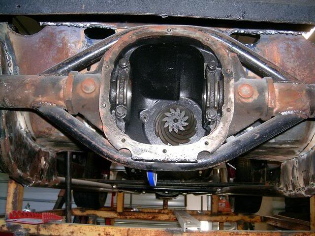
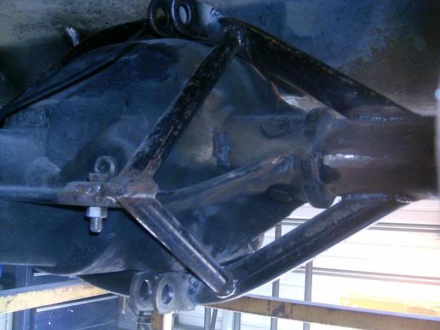
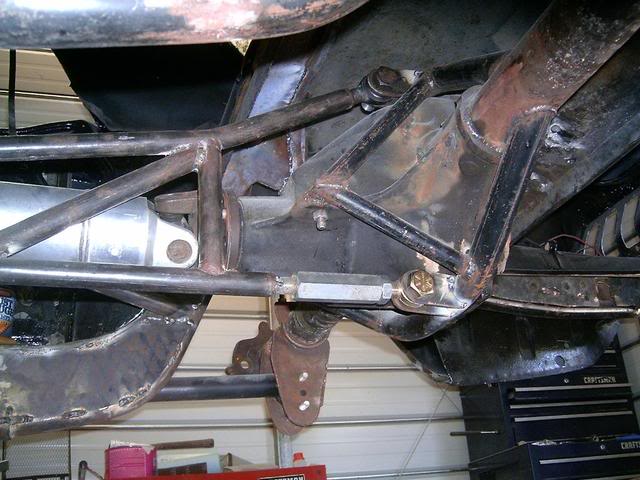
ok guys, heres the finished product. steel is 3/16" mild steel, partially tig welded and the rest is mig welded. the tubing is 1/8" thick. the assembly slips over the snout of the pumpkin(center section) and then has 2 brackets that slip over the pumpkins supports which will be drilled (see holes) and bolted to the pumpkin with grade 8, 1.5"x 3/8" bolts. its pretty close to the stock setup as far as the tq arm mount on the stock 9bolt. My TQ arm is an aftermarket Jegster shorty tunnel mount tq arm.
im pretty happy with the way it turned out... its a really tight fit (bang on with a mallet) even with the bolts not put in i cant pull it off or twist it at all. i wanted it to be removable which is why its not welded but there are a bunch of points at which i can if i ever decided to down the road.
now all thats left is to dissassemble the rear(axles,posi, etc) transfer my brackets over from my 9bolt and then put it all back.
let me know wat you guys think. i took a couple of ideas from some members,BMR, grannys etc. and im super jealous of anyone with a plasma cutter since cutting 3/16" steel with a sawzaw and a jig saw is NOT FUN OR FAST! took me 3 days, last day for painting etc. i think its plenty strong but im interested to see what you guys have to say
looks interesting. Im liking it. I assume you have checked out BIGMODS torque arm mount? he has through bolts going through the case itself with nuts inside the diff. They would add some more strength if you are questioning strength.
It seems that all the force would be transferred to the front of the pumpkin, so unless that broke off, all should be fine.
Either way...doesnt look bad. Im anxious to see it fully attached and set up with a torque arm. I have a bunch of 8.8s since I collect them apparently haha. I gave thought to using one in an f-body build but I never get past thinking about the torque arm mount. I usually assume that Ide just run a ladder bar type setup.
ghettocruiser... lol yea im pretty sure its 3/16" but if it was 1/4" i wouldnt be surprised! it was insane to cut with a jigsaw and sawzaw. yea im tryin to get it in so i can post pics i just swapped both spring perches/panhard bar bracket to the ford 8.8 from the 9bolt.
shagwell... i wanted to do something like yours but once u welded it to the tubes it was no longer removable. in case i trash the rear i wanted it removable, like the idea of bolt on LCARBS... they work fine bolted in but if i ever wanted to have them welded in i could. also one u welded to the axle tubes u changed the tq arm mount. basically when load is on the tq arm its energy is no longer only forced onto the pumpkin/center section but its transfered to the axle tubes. which would require fully welding the axle tubes. granny in my original thread explained it in more detail. i wanted it to only bolt onto the pumpkin so 95% of the load is transfered to the pumpkin and the axle tubes dont need anymore reinforcement. (this is why granny never welds the tubes to the housing on his rears that he builds) bc its not needed with a stock type setup TQ Arm. still yours turned out nice, but u also made your own tq arm, i will be using the tubular shorty jegster one.... which is designed to fit into a stock type setup at the pumpkin.
I realize that you were going for a bolt-on type tq arm mount, just saying I would probably run a brace up the top of the pumpkin and through bolt as 86TA noted. You are placing a lot of stress on the one housing brace. - Basically, the pumpkin is going to try to bend the plates/break the one cast section and twist/slide upwards to pivot out of the collar. A section of 1" angle run up the top and through bolted would add a lot of strength to the mount.
Not trying to bash your design, just a little "constructive criticism"; all-in-all you're doing a great job. It is probably fine as is for mild power, but I'm an over-kill person. I'd rather build it to handle 1000hp and have it never put through over 500 than build it for 500 and have some put it through 700.
I did distribute some of the load to the axle tubes, but the down-leg braces that tie to the factory pinion dampner holes also distribute much of that load to the pumpkin. What you can't really see in those pics is that the pipes that run from tube to tube are also welded to the pumpkin for almost 6", on each side of the pipe. Not really worrried about hurting the housing, as it will be assembled with the proper parts from the git-go. Welding the axles tubes is considerably easy when compared to the fab work you're doing.
i appreciate ur constructive criticism... not really following you with the 1" angle. if you could draw something out like on a napkin id appreciate it lol. i was thinkin maybe a peice of the 3/16" steel curved to fit the pumpkin set at 90degrees (like the bolted areas) but have it twist and reach around to the back support girdle bolts. wont be able to do this until i get the support girdle which is on the way
Welded to the top of your mount and running directly up the top of the housing, then through bolted just before the cover flange. You would have to drill a hole or two through to the inside of the housing. The top would be the most important, and would be less likely to cause you any leaks.
is there enough clearance in the inside of the housing to run a bolt? im most worried about the bolt failing and falling into the gears/fluid, or there just not being enough room for the head of the bolt with all the moving parts.
thats kinda what i was thinking... didnt really wanna do the bottom of the housing but the top would be alil easier
Nice designs. I wish you guys were round when I did mine a couple of years ago. Either of yours look stronger that the sandwitch design I used. I might have to revise it now that I have a plasma cutter.
Nice job.
kory
Just make sure you position it so it's not directly over the ring gear and you'll be fine. A good qualit grade 8 bolt and lock nut would not give you any trouble(use good loc-tite and the primer). - You could drill and tap the housing, so as to have nothing to be able to come loose inside; I'm not sure it would be thick enough to hold well on it's own, but if you tightened a bolt down from the outside a nut on the inside could then be like a jamb nut, thus being very secure.
you guys both need to seek some further education.
its a SAWZALL!
tomato TO MATO... same $HIT! everyone has a diff way of calling/describing something, u must not be a real mechanic... never heard anyone call it a SAWZALL, most abbreviate it to sawzaw.
by the way i googled sawzaw and thats the pic i posted.
custom, how much you charge to make one and send it my way? im on my 3rd rear end with my ls3 swapped 01 ta and it always breaks when i dont have money to buy a better rear and I need the car right now... so if i could do this and not have to be so worried about it untill I up the power more so
custom, how much you charge to make one and send it my way? im on my 3rd rear end with my ls3 swapped 01 ta and it always breaks when i dont have money to buy a better rear and I need the car right now... so if i could do this and not have to be so worried about it untill I up the power more so
Well my ford 8.8 survived behind my 521 BBF, has been as quick at 12s in the 1/4 (traction and valve float issues) and is now behind my 5.3 LS supercharged. This is with the stock 28 spline axles.
I've never contemplated making another one for anyone so I have no idea. I'm not sure if the front nose of the ford 8.8 pumpkin changed at any time either. Is it possible... sure but I don't have a spare rear to build one on.
Less weight an less power to turn the 8.8 and they are just as strong. I have built several that have run 7s in the 1/4 in heavy cars.
Bingo! 9" consume the most power of all the rear ends. I would love to get a S60 built for my car in which case I would just sell the ford 8.8.
Ford 8.8s are cheap anywhere from $150-300 for a complete rear.
Most come with trac lock posi... even if they don't they are cheap to get. Posi can be rebuilt or beefed up with cheap friction plates. Pinions and rings are just as strong as the 12bolt. Your only limited by axle size. Most car (non mustang) run 28 spline axles but mustangs and explorers run 31 spline stock.
I have a total of like $600 in my rear including the price of the rear itself, 3.55 gear swap and new seals/bearings, solid pinon spacer, Moser support girdle/cover, ARP Cap studs and a carbon fiber clutch upgrade.
The claims of the 9 inch eating power is way overblown. One magazine did an article and did a back to back on three rearends, just one article, that seems everyone bases their decision off.12 bolt is comparable to a 8.8. It was a miniscule number the difference. Besides that Ive read people who say they have gone faster(before 9inch swap) and some they have run the same numbers( after the swap) Its a wash really and not worth mentioning. The power loss quoted from running a 9 inch youd think your dropping 50rwhp. Put a spool in a fab 9 rear with aluminum case and see where you are weight wise. I muscled my 9 bolt out and put the fab 9 in and the weight was dam close. So is that a midwest tq arm?
2.375" of hypoid offset in the 9" gearset makes them more like a worm gear and less like a bevel gear. Lots of rubbing transferring power thru a worm gear, not much with a bevel gear. More rubbing action between teeth = more heat generated under load = less efficiency.
8.5 10 bolt, 12 bolt, and Ford 8.8 all have 1.5" of hypoid offset.
If you can gain a few HP here and there plus drop some weight, esp in a race car, why not?
Yes your right. The gain is only a few hp. The hp loss is overstated and overblown. Every internet discussion on this topic quotes that magazine article on rear ends. The hp loss was miniscule to the 12bolt. On a 600hp car you would never know the difference. I like piece of mind though. I never weighed mine but it was the same or less than my 9 bolt, and that is a tooth pick axel compared to the 9 inch. 9 inch is a tried and true vetted axel. What it loses in terms of hp and weight ( and that is using the nodular iron center) makes up for itself in durability and parts availability. Youd think by now most of the bigger manufactures would make an 8.8 bolt in rear for more than just a fox, but they dont. Any reason why? Still wondering on the source of the tq arm and mounting points. Looks exactly like the mwc stuff.
Yes your right. The gain is only a few hp. The hp loss is overstated and overblown. Every internet discussion on this topic quotes that magazine article on rear ends. The hp loss was miniscule to the 12bolt. On a 600hp car you would never know the difference. I like piece of mind though. I never weighed mine but it was the same or less than my 9 bolt, and that is a tooth pick axel compared to the 9 inch. 9 inch is a tried and true vetted axel. What it loses in terms of hp and weight ( and that is using the nodular iron center) makes up for itself in durability and parts availability. Youd think by now most of the bigger manufactures would make an 8.8 bolt in rear for more than just a fox, but they dont. Any reason why? Still wondering on the source of the tq arm and mounting points. Looks exactly like the mwc stuff.
Using less hp isn't the only reason, sure it's good to know ur saving a few but does it matter no! The whole point is dollar per hp it's able to handle. Stock 8.8 are stronger than 9 bolts and 10bolts and are the same price if not cheaper most of the time and not to mention the cost of replacing parts are cheap compared to the 9 bolt. Even then the cost is comparable to a 10bolt but the parts are stronger.
If your going to spend the money on a 9" u might as well just go strange 60. Stronger than the 9" and cost about the same.
Also 8.8s are found just about everywhere, mustangs, crown Vic, Mercury marquis, F150s yadda yadda. They are fords go to rear.
Speaking of the 9" strength first time I was at the strip guy was loading his car at the line and BAM car lurched forward and out came the 9" in peices. Even then I know their strong but I just not a fan of the design and the offset pinon. There are better designs out their. Hell even my RAM has the Dana 60 in it.
I started mine about 8 years ago, drove it, then removed to have it narrowed. I got it narrowed, Eaton posi, 4:30 gears and lost interest for awhile. I'm getting back to it. I have 235 miles on the engine. I think it was an 84 crown vic, needed spring perches and torque arm mount. Now it needs axles and brakes. I'll play with the 7.5 4:10 posi for awhile.
ok guys, heres the finished product. steel is 3/16" mild steel, partially tig welded and the rest is mig welded. the tubing is 1/8" thick. the assembly slips over the snout of the pumpkin(center section) and then has 2 brackets that slip over the pumpkins supports which will be drilled (see holes) and bolted to the pumpkin with grade 8, 1.5"x 3/8" bolts. its pretty close to the stock setup as far as the tq arm mount on the stock 9bolt. My TQ arm is an aftermarket Jegster shorty tunnel mount tq arm.
im pretty happy with the way it turned out... its a really tight fit (bang on with a mallet) even with the bolts not put in i cant pull it off or twist it at all. i wanted it to be removable which is why its not welded but there are a bunch of points at which i can if i ever decided to down the road.
now all thats left is to dissassemble the rear(axles,posi, etc) transfer my brackets over from my 9bolt and then put it all back.
let me know wat you guys think. i took a couple of ideas from some members,BMR, grannys etc. and im super jealous of anyone with a plasma cutter since cutting 3/16" steel with a sawzaw and a jig saw is NOT FUN OR FAST! took me 3 days, last day for painting etc. i think its plenty strong but im interested to see what you guys have to say
I started mine about 8 years ago, drove it, then removed to have it narrowed. I got it narrowed, Eaton posi, 4:30 gears and lost interest for awhile. I'm getting back to it. I have 235 miles on the engine. I think it was an 84 crown vic, needed spring perches and torque arm mount. Now it needs axles and brakes. I'll play with the 7.5 4:10 posi for awhile.
nope, it�s a one off. Good news is the rear is still in service and has survived no issues. It�s now holding up to 3 years of boosted 5.3 LS or about 650 crank hp. I�ve also drilled the axles out for GM bolt pattern with a hand drill and run MT street Drag radials and all is ok.
nope, it�s a one off. Good news is the rear is still in service and has survived no issues. It�s now holding up to 3 years of boosted 5.3 LS or about 650 crank hp. I�ve also drilled the axles out for GM bolt pattern with a hand drill and run MT street Drag radials and all is ok.
Yes Ive seen those and Ive also heard of them failing at the welds... since that style needs welding to the cast iron case. Its a very difficult thing to weld cast for the average person. I can weld pretty well on most metals but I'm not comfortable on welding cast iron given its such a stressed/important key suspension piece.
If you have a machine shop perform the service it will be fine, or use a high nickel rod most welds break because these people used the wrong welder or didn't get proper penetration. I suggest a machine shop because who else has more experience welding cast iron and they usually guarantee their work. Yes on some of these welds break but it's usually because of installation experience and a lack there of
If you have a machine shop perform the service it will be fine, or use a high nickel rod most welds break because these people used the wrong welder or didn't get proper penetration. I suggest a machine shop because who else has more experience welding cast iron and they usually guarantee their work. Yes on some of these welds break but it's usually because of installation experience and a lack there of
Sure but then you have added cost of transport, paying for the service, plus once its welded your $hit outa luck if you screw up that rear. That actually happened to me... I totaled my first rear (slid into a curb) and bend the axle tube and snapped the axel while destroying the rim. I just slid the bolt on tq arm mount and slid it over the replacement rear. Had it been welded it would have been wasted. Also. its not usually just the rod thats the issue, with cast iron you have to/should preheat the area for welding and then have a slow cool down. Just saying that cast iron is a finicky little biotch and I prefer not to have the strength of the part be depended on a cast iron weld.
If you can weld or know someone who can lay a good cast iron weld the bracket kit you posted would be of great value as long as you don't destroy the rear. Overall costs I have less in my material than purchasing that kit and its reusable.
 06-06-2009, 03:19 PM