There's Something Wrong With Your Head
 01-10-2010, 12:58 AM
#1
Supreme Member

Thread Starter
iTrader: (2)
Join Date: May 2007
Location: right behind you
Posts: 2,574
Likes: 0
Received 0 Likes
on
0 Posts
Car: '85 maro
Engine: In the works...
Transmission: TH700 R4
Axle/Gears: 3.73 posi
There's Something Wrong With Your Head
Heads, actually. They're iron. So what do you do? Get 3x00 heads.
But wait, you don't want to swap in a 3.4 block and you certainly don't want to drop in a whole rwd motor. What a headache!") And you can't use a distributor without some major hacking. Well I may have the solution for the meiserly penny pincher and the DIY'er. 'Cause I'm a bit of both.
And you can't use a distributor without some major hacking. Well I may have the solution for the meiserly penny pincher and the DIY'er. 'Cause I'm a bit of both. 
I've recieved a few questions recently about how to set up a DIS ignition system. So I figured I might as well be the guinea pig. You'll need a coil pack & oil pump drive from a 3x00 and either the 7x sensor from the 3x00 or an abs sensor from just about anything (mine's from a '99 durango). I preffer the abs sensor because it has a nice strong neodymium magnet that gives a clear strong signal.
Here's a pic of the 'bracket'. It's a washer welded to the side of the timing tab with a flat ground on one side to keep the sensor from rotating. Placement on the tab isn't critical since you're going to adjust it later, just needs to line up with the reluctor and the 0 mark on the tab. Adjust the air gap to .04"
SANY0364.jpg?SSImageQuality=Full
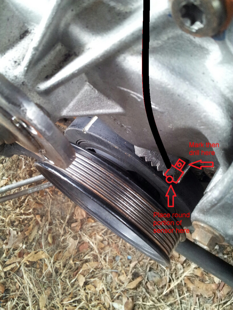
For those of you with the longer tab missing the sensor tube you can place the sensor like so by grinding the 'v' for the 0 mark back 1/8", drilling a bolt hole and adjusting the air gap with washers.
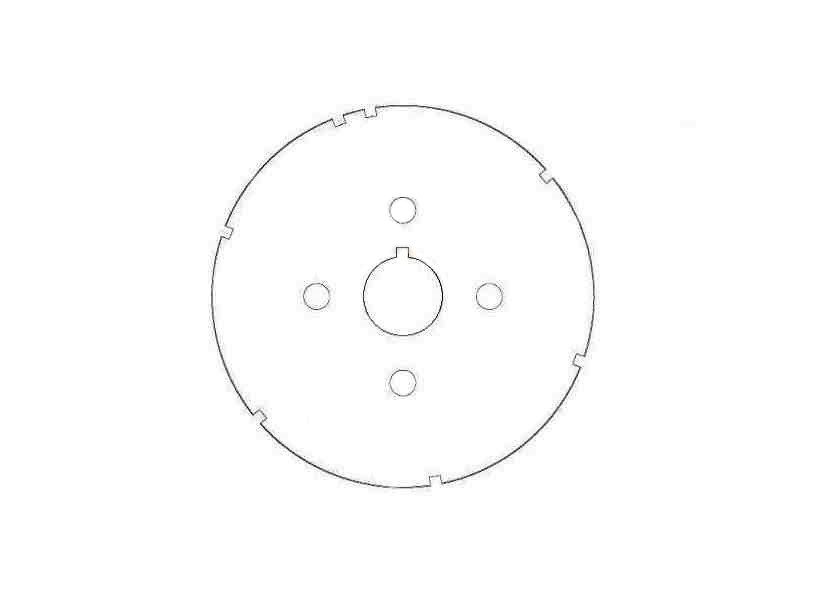
You can either cut notches in the pulley using this diagram as a template or transfer it to a 1/4" steel plate to make a reluctor.
When you swap connector ends on the abs sensor make sure you have the polarity correct. If not the car won't fire, just swap wires.
Rewiring should work as follows.
B ----------> Ign pwr (coil orange or pink wire)
A ----------> Crank sens. high
B ----------> N/A
C ----------> Crank sens. low
A ----------> Bypass (dist. pin B)
B ----------> EST (dist. pin D)
C ----------> Tach Lead (coil black w/ white stripe wire)
D ----------> N/A
E ----------> Refrence (dist. pin C)
F ----------> Ground (dist. pin A)
You don't neccecarily have to replace the distributor with an oil pump drive, but replacement's simple. Just 1 bolt. You won't need new plug wires either, just move the longest to the far side and route behind the plenum, then trim the rest to fit. The coil pack almost bolts in place, all you need to do is cut off one side of the coil bracket and enlarge the bolt holes a bit.
And finally here's a bin to get you started, post #158. A few features like an mpg estimate and power estimate are included in the datalog file and it's compatible with any vehicle using $6E, not just DIS.
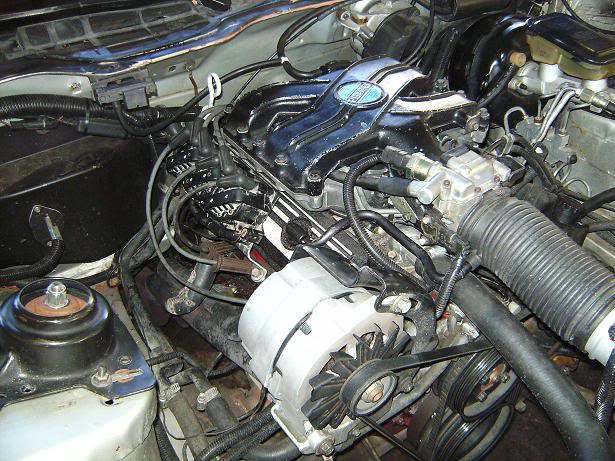
After everything's assembled start it up and verify your timing with a timing light. You can program another chip with the main table set to 0* to make things a little easier or disconnect the EST line. You will need to make your own timing marks somewhere if you mount the sensor to the timing tab since the sensor moves with it. And please, don't try adjusting the sensor with the motor running. Here's a pic of it assembled. Looks right at home, doesn't it?
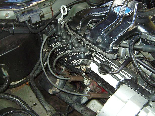
And a close up.
But wait, you don't want to swap in a 3.4 block and you certainly don't want to drop in a whole rwd motor. What a headache!
And you can't use a distributor without some major hacking. Well I may have the solution for the meiserly penny pincher and the DIY'er. 'Cause I'm a bit of both. I've recieved a few questions recently about how to set up a DIS ignition system. So I figured I might as well be the guinea pig. You'll need a coil pack & oil pump drive from a 3x00 and either the 7x sensor from the 3x00 or an abs sensor from just about anything (mine's from a '99 durango). I preffer the abs sensor because it has a nice strong neodymium magnet that gives a clear strong signal.
Here's a pic of the 'bracket'. It's a washer welded to the side of the timing tab with a flat ground on one side to keep the sensor from rotating. Placement on the tab isn't critical since you're going to adjust it later, just needs to line up with the reluctor and the 0 mark on the tab. Adjust the air gap to .04"
SANY0364.jpg?SSImageQuality=Full
For those of you with the longer tab missing the sensor tube you can place the sensor like so by grinding the 'v' for the 0 mark back 1/8", drilling a bolt hole and adjusting the air gap with washers.
You can either cut notches in the pulley using this diagram as a template or transfer it to a 1/4" steel plate to make a reluctor.
When you swap connector ends on the abs sensor make sure you have the polarity correct. If not the car won't fire, just swap wires.
Rewiring should work as follows.
DIS pin -----> Connection
A ----------> Ground to blockB ----------> Ign pwr (coil orange or pink wire)
A ----------> Crank sens. high
B ----------> N/A
C ----------> Crank sens. low
A ----------> Bypass (dist. pin B)
B ----------> EST (dist. pin D)
C ----------> Tach Lead (coil black w/ white stripe wire)
D ----------> N/A
E ----------> Refrence (dist. pin C)
F ----------> Ground (dist. pin A)
You don't neccecarily have to replace the distributor with an oil pump drive, but replacement's simple. Just 1 bolt. You won't need new plug wires either, just move the longest to the far side and route behind the plenum, then trim the rest to fit. The coil pack almost bolts in place, all you need to do is cut off one side of the coil bracket and enlarge the bolt holes a bit.
And finally here's a bin to get you started, post #158. A few features like an mpg estimate and power estimate are included in the datalog file and it's compatible with any vehicle using $6E, not just DIS.
After everything's assembled start it up and verify your timing with a timing light. You can program another chip with the main table set to 0* to make things a little easier or disconnect the EST line. You will need to make your own timing marks somewhere if you mount the sensor to the timing tab since the sensor moves with it. And please, don't try adjusting the sensor with the motor running
. Here's a pic of it assembled. Looks right at home, doesn't it?And a close up.
Last edited by bl85c; 03-10-2014 at 10:17 PM. Reason: Clarification
 01-11-2010, 10:11 PM
#2
Senior Member

Join Date: Nov 2001
Location: Tenino, Washington
Posts: 825
Likes: 0
Received 0 Likes
on
0 Posts
Car: 89 f-bird and some others
Engine: 3.4
Transmission: 700R4
Axle/Gears: 3.42
Re: There's Something Wrong With Your Head
Saw some 3100s at pick-a-part last week.
Tempting.
I can't even get the 165 swap to work though. I can't imagine the nightmare I'd face with a head change, SFI, distributorless ingnition, wiring harness swap, and throttle cable linkage fabrication.
Tempting.
I can't even get the 165 swap to work though. I can't imagine the nightmare I'd face with a head change, SFI, distributorless ingnition, wiring harness swap, and throttle cable linkage fabrication.
01-11-2010, 11:28 PM
#3
Supreme Member
Thread Starter
iTrader: (2)
Join Date: May 2007
Location: right behind you
Posts: 2,574
Likes: 0
Received 0 Likes
on
0 Posts
Car: '85 maro
Engine: In the works...
Transmission: TH700 R4
Axle/Gears: 3.73 posi
Re: There's Something Wrong With Your Head
Why do you need to swap harnesses? Rewiring's pretty easy.
Last edited by bl85c; 01-13-2010 at 11:14 PM.
01-15-2010, 06:51 PM
#4
Supreme Member
Thread Starter
iTrader: (2)
Join Date: May 2007
Location: right behind you
Posts: 2,574
Likes: 0
Received 0 Likes
on
0 Posts
Car: '85 maro
Engine: In the works...
Transmission: TH700 R4
Axle/Gears: 3.73 posi
Re: There's Something Wrong With Your Head
Still no luck. I'm going to take a second look at how I have this wired and then it's down to the sensor.
Edit- you can ignore the rest of this stuff. I went back and edited the 1st post after I got it running.
Edit- you can ignore the rest of this stuff. I went back and edited the 1st post after I got it running.
Last edited by bl85c; 04-25-2011 at 12:11 AM.
01-15-2010, 09:33 PM
#5
Supreme Member
iTrader: (8)
Join Date: Aug 2003
Location: LeRoy, NY
Posts: 7,240
Likes: 0
Received 5 Likes
on
4 Posts
Car: 2003 Hyundai Tiburon GT
Engine: 2.7L V6
Transmission: 6-speed
Axle/Gears: 4.41
Re: There's Something Wrong With Your Head
The connections look good according to swap charts I've seen. However, I could swear that the sensor connections were yellow and purple (similar to the VSS)... Anyways, if you have a scanner, look at the 7x signal... If it isn't giving one while cranking, try a new sensor. A guy I went to school with had problems with his 3100 Lumina where the CKP was only putting out a signal when the key was released from cranking...
You can also check for a VAC signal coming out of the sensor while cranking...
You can also check for a VAC signal coming out of the sensor while cranking...
01-16-2010, 08:20 AM
#6
Moderator
iTrader: (1)

Join Date: Mar 2002
Location: Chasing Electrons
Posts: 18,400
Likes: 0
Received 215 Likes
on
201 Posts
Car: check
Engine: check
Transmission: check
Re: There's Something Wrong With Your Head
I think that you are using the wrong crank sensor. It needs to be a reluctor type sensor. With you mentioning wiring +5 v to the sensor, that would be a hall effect.
Then for the reluctor type sensor pin B of the DIS module sensor connector is the ground for the shield. The sensor wires are a twisted-pair and are shielded.
RBob.
Then for the reluctor type sensor pin B of the DIS module sensor connector is the ground for the shield. The sensor wires are a twisted-pair and are shielded.
RBob.
01-16-2010, 02:04 PM
#7
Supreme Member
Thread Starter
iTrader: (2)
Join Date: May 2007
Location: right behind you
Posts: 2,574
Likes: 0
Received 0 Likes
on
0 Posts
Car: '85 maro
Engine: In the works...
Transmission: TH700 R4
Axle/Gears: 3.73 posi
Re: There's Something Wrong With Your Head
Fwd sensors are yellow & purple, the 3.4 is red & green. I'm not getting a signal. According to the diagram I have for the sensor A (red) is switched ign. power, B (green) is signal and C (black) is low. I believe it's supposed to be 12v like the cam sensor, but the 7x sensor is 5v(?) and I didn't want to start off by roasting the sensor/module. If it's 12v I could use a voltage splitter to bring it down to 5v for the module... still researching it. I had the same thoughts on the sensor though. I might not be able to use it the way I want.
Last edited by bl85c; 01-17-2010 at 12:57 PM.
Trending Topics
01-16-2010, 06:56 PM
#8
Moderator
iTrader: (1)
Join Date: Mar 2002
Location: Chasing Electrons
Posts: 18,400
Likes: 0
Received 215 Likes
on
201 Posts
Car: check
Engine: check
Transmission: check
Re: There's Something Wrong With Your Head
If the DIS module you are using expects a 24X signal, what you did with the crank trigger wheel won't work. Regardless of the crank sensor.
From the change you made in the crank trigger wheel you need to use a 3.1l ignition module. One that expects a a 6-slot + sync trigger(s). Even then you need to be sure the sensor pulse is the correct polarity for the desired timing events.
Need more info on what you are actually using for parts. As the mix & match isn't matching up.
RBob.
01-16-2010, 08:18 PM
#9
Supreme Member
Thread Starter
iTrader: (2)
Join Date: May 2007
Location: right behind you
Posts: 2,574
Likes: 0
Received 0 Likes
on
0 Posts
Car: '85 maro
Engine: In the works...
Transmission: TH700 R4
Axle/Gears: 3.73 posi
Re: There's Something Wrong With Your Head
It's the 24x sensor and coil pack from a 3.4 camaro with the reluctor on the balancer modified like a 7x. According to others that have done the swap only the 7x signal is neccecary.
There was one small change I noticed on the 3.4 coil pack and that was on the 3pin connector, pin c was in b- so the sensor was just grounded. Swapped them and that didn't make a difference. I may grab a coil pack from a 3400 next time I'm at the jy.
There was one small change I noticed on the 3.4 coil pack and that was on the 3pin connector, pin c was in b- so the sensor was just grounded.
Swapped them and that didn't make a difference. I may grab a coil pack from a 3400 next time I'm at the jy.
01-17-2010, 09:20 AM
#10
Moderator
iTrader: (1)
Join Date: Mar 2002
Location: Chasing Electrons
Posts: 18,400
Likes: 0
Received 215 Likes
on
201 Posts
Car: check
Engine: check
Transmission: check
Re: There's Something Wrong With Your Head
Checking some information on the 3.4l f-body engine, the 3X signal to the ICM is from a reluctor pickup. A hall effect pickup won't work in this case. On a 3.4l engine this is from the reluctor ring that is part of the crankshaft. Sensor is located mid-block, passenger side.
The cam & 24X signals go directly to the PCM. Bypassing the ICM all together.
So you need to use a reluctor pickup for the damper vanes. Or put together a circuit to convert the hall effect output to a reluctor output signal. Something as simple as a series capacitor may work. Note that the 24X CKP sensor gets +12V switched (not +5 volts).
RBob.
01-17-2010, 12:35 PM
#12
Supreme Member
Thread Starter
iTrader: (2)
Join Date: May 2007
Location: right behind you
Posts: 2,574
Likes: 0
Received 0 Likes
on
0 Posts
Car: '85 maro
Engine: In the works...
Transmission: TH700 R4
Axle/Gears: 3.73 posi
Re: There's Something Wrong With Your Head
Perhaps I could bypass the amplifier & stuff in the coil module and send the hall signal direct?? After the reluctor signal's processed both end up looking pretty much the same, no? Just a square wave signal. Looks like I may have to wire this thing backwards or reverse how I have the reluctor set up. 
Last edited by bl85c; 01-17-2010 at 12:46 PM.
01-17-2010, 03:03 PM
#13
Moderator
iTrader: (1)
Join Date: Mar 2002
Location: Chasing Electrons
Posts: 18,400
Likes: 0
Received 215 Likes
on
201 Posts
Car: check
Engine: check
Transmission: check
Re: There's Something Wrong With Your Head
Perhaps I could bypass the amplifier & stuff in the coil module and send the hall signal direct?? After the reluctor signal's processed both end up looking pretty much the same, no? Just a square wave signal. Looks like I may have to wire this thing backwards or reverse how I have the reluctor set up.
If you really want a nice set up. Look for a 3.8l Buick Quick Start system. Uses an 18x and a 3X vane on the damper (integral hall-effect sensors). Along with the ICM and DIS 3-coil pack. The ICM gets both the 3x & 18x signals and will sync up and fire a coil within 120* of crank rotation.
Smooth idle and running along with great crank to run time.
RBob.
01-17-2010, 03:45 PM
#14
Supreme Member
Thread Starter
iTrader: (2)
Join Date: May 2007
Location: right behind you
Posts: 2,574
Likes: 0
Received 0 Likes
on
0 Posts
Car: '85 maro
Engine: In the works...
Transmission: TH700 R4
Axle/Gears: 3.73 posi
Re: There's Something Wrong With Your Head
I meant in the module... scratch off a trace, jumper to elsewhere. F up the board and try again, LOL. Buick ignition is a much better idea.
01-17-2010, 07:07 PM
#15
Supreme Member
Thread Starter
iTrader: (2)
Join Date: May 2007
Location: right behind you
Posts: 2,574
Likes: 0
Received 0 Likes
on
0 Posts
Car: '85 maro
Engine: In the works...
Transmission: TH700 R4
Axle/Gears: 3.73 posi
Re: There's Something Wrong With Your Head
I think I'll see this project out how I planned it. I'll need it wired for the 3.4 coil pack when I get the hybrid built. Rewiring it again won't make sense in my case but adapting the buick igniton would be a good way for others that want to keep their 2.8 or 3.1 block. A different sensor bracket would be needed and you'd have to drill the 2.8/3.1 balancer to mount the reluctors. Wiring would be a little more complicated for the 3.8 coil pack and you'd have to rearrange the plug wires for the correct firing order. I may make a writeup for the buick ignition as well. Mind explaining the capacitor idea?
Here's another idea. Trigger a reluctor sensor with the hall. Anti-engineering at it's best.
Here's another idea. Trigger a reluctor sensor with the hall. Anti-engineering at it's best.
Last edited by bl85c; 01-17-2010 at 08:07 PM.
01-20-2010, 09:55 PM
#16
Supreme Member
Thread Starter
iTrader: (2)
Join Date: May 2007
Location: right behind you
Posts: 2,574
Likes: 0
Received 0 Likes
on
0 Posts
Car: '85 maro
Engine: In the works...
Transmission: TH700 R4
Axle/Gears: 3.73 posi
Re: There's Something Wrong With Your Head
Well that idea was a bust, I figured as much. Only 2.5 milliamps through the signal wire and that won't run an electromagnet. So hall triggering the reluctor sensor is out. Mounting the buick sensor might be a challenge as well, looks like it's too fat to fit between the balancer & timing cover. Good news is that it runs, but I had to cheat. Used a probe from a timing light and cut notches in the balancer's outer ring- not that I suggest anyone else do that because the outer ring will change position over time. I just wanted to see it run. The coils even bolt right inplace of the stock one once you cut the other side of the mounting bracket off and add a couple shims. Still going to try and get the hall to run this thing.
Last edited by bl85c; 01-20-2010 at 10:01 PM.
01-21-2010, 09:25 AM
#17
Moderator
iTrader: (1)
Join Date: Mar 2002
Location: Chasing Electrons
Posts: 18,400
Likes: 0
Received 215 Likes
on
201 Posts
Car: check
Engine: check
Transmission: check
Re: There's Something Wrong With Your Head
I was looking at this the other day. Not much room on the engine side of the damper for a trigger wheel. Timing cover is in the way. Thought about notching the outside of the damper, but as you mention it is going to be moving to help dampen harmonics. Let alone if it starts to slip.
Could place a trigger wheel between the damper & pulley. Would need to see if the damper snout could be shortened by the same amount. But then the timing cover becomes an issue.
Maybe make the damper thinner by the same amount as the thickness of the wheel. It looks like a 3/16" thick wheel would do the trick (1/4" thick would be better). Then again, the center area of the wheel could be thinner then the edge. Maybe 1/8" or 3/32" to lesson the change in position and required trimming of parts.
Two other ideas are to either notch the edge of the pulley. Or mount the wheel to the back of the pulley. This would be a ring mounted to the back side that did not interfere with the damper.
Note that the trigger signal to the ICM is critical. If the reluctor is wired backwards the ICM won't trigger. This surprised me as distributor ICMs don't care about the polarity of the signal.
RBob.
01-22-2010, 09:57 PM
#18
Senior Member
iTrader: (2)

Join Date: May 2005
Location: Baltimore, MD
Posts: 841
Likes: 0
Received 0 Likes
on
0 Posts
Car: 09 Cobalt SS Sedan. 92 Z28 vert
Engine: 2.0T EFR6758; 5.0TT T3/T4 8psi
Transmission: F40; 700r4
Axle/Gears: 3.76 LSD; 3.23 posi
Re: There's Something Wrong With Your Head
after/if you get the hall effect sensor to work the ICM... let me know how you get your tach to work please.
01-22-2010, 10:09 PM
#19
Supreme Member
Thread Starter
iTrader: (2)
Join Date: May 2007
Location: right behind you
Posts: 2,574
Likes: 0
Received 0 Likes
on
0 Posts
Car: '85 maro
Engine: In the works...
Transmission: TH700 R4
Axle/Gears: 3.73 posi
Re: There's Something Wrong With Your Head
No prob.
I was looking into using a small rectifier with a capacitor to make the signal more parabola-like, but the problem again is the tiny amperage it's giving. Anyone know where to source a small rectifier that would work properly here? If all else fails I may just switch another source with a transistor to get what I need.
I was looking into using a small rectifier with a capacitor to make the signal more parabola-like, but the problem again is the tiny amperage it's giving. Anyone know where to source a small rectifier that would work properly here? If all else fails I may just switch another source with a transistor to get what I need.
01-23-2010, 03:10 PM
#21
Senior Member
iTrader: (2)
Join Date: May 2005
Location: Baltimore, MD
Posts: 841
Likes: 0
Received 0 Likes
on
0 Posts
Car: 09 Cobalt SS Sedan. 92 Z28 vert
Engine: 2.0T EFR6758; 5.0TT T3/T4 8psi
Transmission: F40; 700r4
Axle/Gears: 3.76 LSD; 3.23 posi
Re: There's Something Wrong With Your Head
didn't intend to hyjack, just wanted to show support here. I have the white tach signal wire from the stock v6 harness to pin C still no tach. please respond in the v6 forum "my 3.1/3100 hybrid turbo project"
01-23-2010, 03:24 PM
#22
Moderator
iTrader: (1)
Join Date: Mar 2002
Location: Chasing Electrons
Posts: 18,400
Likes: 0
Received 215 Likes
on
201 Posts
Car: check
Engine: check
Transmission: check
Re: There's Something Wrong With Your Head
Here is a picture of the trigger input to a 3.4l Camaro DIS module. This is from a reluctor pickup. The waveform first goes positive to arm the zero-crossing detector. The sharp falling signal is what triggers the DIS module. The faster the signal falls through zero the better.
Note that the horizontal portion of the trace (center of display) is zero volts. In this case the signal goes +10 V then drops through zero to -7 V.
I also took a look at the TACH output from the DIS module. It is a 5.5V square wave. Just pulses of about 2 msec at 1200 RPM (don't quote me on this part).
Being that the 3rd gen tach is connected to the coil - side. It will be getting a 12V square wave along with an inductive kick pulse.
As such the 3rd gen tach may work with just the 12 V pulses. Can find out easily enough by using a level shifter (transistor and a couple of resistors).
If that doesn't work then will need to add an inductor to the circuit to provide a higher voltage short pulse at the being of the 12 V square wave rise time. In this case it may be easier to see if another tach could be used with the DIS module.
RBob.
Last edited by RBob; 01-24-2010 at 05:31 PM.
01-23-2010, 04:45 PM
#23
Senior Member
iTrader: (2)
Join Date: May 2005
Location: Baltimore, MD
Posts: 841
Likes: 0
Received 0 Likes
on
0 Posts
Car: 09 Cobalt SS Sedan. 92 Z28 vert
Engine: 2.0T EFR6758; 5.0TT T3/T4 8psi
Transmission: F40; 700r4
Axle/Gears: 3.76 LSD; 3.23 posi
Re: There's Something Wrong With Your Head
I assume most aftermarket tachs are designed to fit many applications... maybe I'll check the fwd message board for a tach that is known to work.
01-23-2010, 08:02 PM
#24
Supreme Member
Thread Starter
iTrader: (2)
Join Date: May 2007
Location: right behind you
Posts: 2,574
Likes: 0
Received 0 Likes
on
0 Posts
Car: '85 maro
Engine: In the works...
Transmission: TH700 R4
Axle/Gears: 3.73 posi
Re: There's Something Wrong With Your Head
Here is a picture of the trigger input to a 3.4l Camaro DIS module. This is from a reluctor pickup. The waveform first goes positive to arm the zero-crossing detector. The sharp falling signal is what triggers the DIS module. The faster the signal falls through zero the better.
Note that the horizontal portion of the trace (center of display) is zero volts. In this case the signal goes +10 V then drops through zero to -7 V.
I also took a look at the TACH output from the DIS module. It is a 5.5V square wave. Just pulses of about 2 msec at 1200 RPM (don't quote me on this part).
Being that the 3rd gen tach is connected to the coil - side. It will be getting a 12V square wave along with an inductive kick pulse.
As such the 3rd gen tach may work with just the 12 V pulses. Can find out easily enough by using a level shifter (transistor and a couple of resistors).
If that doesn't work then will need to add an inductor to the circuit to provide a higher voltage short pulse at the being of the 12 V square wave rise time. In this case it may be easier to see if another tach could be used with the DIS module.
RBob.
Note that the horizontal portion of the trace (center of display) is zero volts. In this case the signal goes +10 V then drops through zero to -7 V.
I also took a look at the TACH output from the DIS module. It is a 5.5V square wave. Just pulses of about 2 msec at 1200 RPM (don't quote me on this part).
Being that the 3rd gen tach is connected to the coil - side. It will be getting a 12V square wave along with an inductive kick pulse.
As such the 3rd gen tach may work with just the 12 V pulses. Can find out easily enough by using a level shifter (transistor and a couple of resistors).
If that doesn't work then will need to add an inductor to the circuit to provide a higher voltage short pulse at the being of the 12 V square wave rise time. In this case it may be easier to see if another tach could be used with the DIS module.
RBob.
Last edited by bl85c; 01-23-2010 at 08:22 PM.

 01-28-2010, 01:14 AM
#27
Supreme Member
Thread Starter
iTrader: (2)
Join Date: May 2007
Location: right behind you
Posts: 2,574
Likes: 0
Received 0 Likes
on
0 Posts
Car: '85 maro
Engine: In the works...
Transmission: TH700 R4
Axle/Gears: 3.73 posi
Re: There's Something Wrong With Your Head
Well getting the hall to do what I want is a little difficult and IMO a bit to complicated for the average diy'er. So here's what I did. Alot of distortion in the vid so it sounds like it's running without oil lol.
I hacked notches into the pulley. The white thing on the front of the motor is an abs sensor from a '99 durango I had laying around. The 'bracket' is just a washer welded to the side of the timing tab. I'll post a pic up when I redo the writeup tomorrow. The only problem with what the guy on the fiero forum did is cut the notches into the balancer's inertia ring. They will move eventually, especially gm balancers. Good design otherwise. I wish I would've gone the ghetto route and just cut the damn pulley in the first place since it was so easy. If you want to make a reluctor here's a diagram you can transfer to a 1/4" steel plate that bolts between the balancer and pulley.

I hacked notches into the pulley.
The white thing on the front of the motor is an abs sensor from a '99 durango I had laying around. The 'bracket' is just a washer welded to the side of the timing tab. I'll post a pic up when I redo the writeup tomorrow. The only problem with what the guy on the fiero forum did is cut the notches into the balancer's inertia ring. They will move eventually, especially gm balancers. Good design otherwise. I wish I would've gone the ghetto route and just cut the damn pulley in the first place since it was so easy. If you want to make a reluctor here's a diagram you can transfer to a 1/4" steel plate that bolts between the balancer and pulley. Last edited by bl85c; 01-30-2010 at 11:07 PM.
01-28-2010, 12:17 PM
#28
Moderator
iTrader: (1)
Join Date: Mar 2002
Location: Chasing Electrons
Posts: 18,400
Likes: 0
Received 215 Likes
on
201 Posts
Car: check
Engine: check
Transmission: check
Re: There's Something Wrong With Your Head
Cool, you have it running on the DIS. I was wondering what you did in the cal to get the timing correct. And, have you checked the timing with the EST/BYPASS open vs. with it closed.
When playing with the DIS set up I had the trigger wheel in a lathe, ECM on a test bench, scope, laptop, and timing light nearby. With the engine 'not running' (in bypass mode), the DIS fired at the trailing edge of the notch.
With the engine running, a commanded 10* BTDC moved the timing ahead by the proper 10*. Same with 20* commanded timing, it moved ahead by 20* on the trigger wheel.
This was using -70 for Min SA (max retard), 0 for max SA, and 60 for Initial SA.
However, my understanding is that on a 3.4l engine the base timing during cranking is at 10* BTDC. Which means that the trailing edge of the notch is at 10* prior to TDC of the engine. Can anyone with a 3.4l crank verify this??
Which also means that the initial SA in the cal should be at 70*, not 60. And the commanded 10* of timing should be at the same point on the wheel as during cranking.
In the same way, if you want the engine to crank at 10* BTDC (same as a stock distributor in a 3.1l engine), the trigger wheel needs to be offset by 10* from TDC.
RBob.
01-30-2010, 01:27 PM
#29
Supreme Member
Thread Starter
iTrader: (2)
Join Date: May 2007
Location: right behind you
Posts: 2,574
Likes: 0
Received 0 Likes
on
0 Posts
Car: '85 maro
Engine: In the works...
Transmission: TH700 R4
Axle/Gears: 3.73 posi
Re: There's Something Wrong With Your Head
I copied what ttypecamaro did and set max spark to 90*, base to 0* and added 50* to the coolant comp. table to get a max of 40*. 90* is the most you can put in $6E and you can't put in negative numbers, kinda sucks but I won't need more than 40* with the new motor anyway. Long cranking when it's cold, but starts instantly warm. It still reads at base timing with the connector disconnected, which confused me a bit because I thought I'd get like 70* or somthing crazy without the ecm commanding it. All the 3x00 motors crank at 10*.
Last edited by bl85c; 01-30-2010 at 10:14 PM.
01-30-2010, 03:52 PM
#30
Moderator
iTrader: (1)
Join Date: Mar 2002
Location: Chasing Electrons
Posts: 18,400
Likes: 0
Received 215 Likes
on
201 Posts
Car: check
Engine: check
Transmission: check
Re: There's Something Wrong With Your Head
For the long cold crank make sure that the cal is set up to pulse the injectors on the first DRP. Some of the $6E calibrations are set up to not pulse until 6 to 8 DRPs occur. This makes for long cold cranking.
The MAX retard (min SA) value can be negative. In the cal it is a 2 byte values that is signed. The stock V8 distributor cal's use -3.5* for this value. It may be that the ECU/XDF isn't set up correctly. In TP v4 I've found this equation works:
0.351563 * X + -23040.000000
RBob.
The MAX retard (min SA) value can be negative. In the cal it is a 2 byte values that is signed. The stock V8 distributor cal's use -3.5* for this value. It may be that the ECU/XDF isn't set up correctly. In TP v4 I've found this equation works:
0.351563 * X + -23040.000000
RBob.
01-30-2010, 05:36 PM
#31
Senior Member
iTrader: (2)
Join Date: May 2005
Location: Baltimore, MD
Posts: 841
Likes: 0
Received 0 Likes
on
0 Posts
Car: 09 Cobalt SS Sedan. 92 Z28 vert
Engine: 2.0T EFR6758; 5.0TT T3/T4 8psi
Transmission: F40; 700r4
Axle/Gears: 3.76 LSD; 3.23 posi
Re: There's Something Wrong With Your Head
my wheel is set 8* advanced so my max adv. is only 38*. I also found improved starting when I changed the first 3 drp pw multipliers to non-zero. Starting got even better when I realized it was using 18* adv on cranking. I had to set the crank spark advance to 2* in the chip instead of stock 10* (2+8=10).
Brushing up on my transistor electronics in reference to boosting the tach signal... common emmiter / switching circuit... npn transistor and 1kOhm from Vcc to the collector: when Vbe=0V(DIS signal) then Vce=12V(tach signal); when Vbe~5V(DIS signal) then Vce~1V; Will 11V be enough difference to run the tach? Or can we assume Vcc~14.5V from the alternator?
Brushing up on my transistor electronics in reference to boosting the tach signal... common emmiter / switching circuit... npn transistor and 1kOhm from Vcc to the collector: when Vbe=0V(DIS signal) then Vce=12V(tach signal); when Vbe~5V(DIS signal) then Vce~1V; Will 11V be enough difference to run the tach? Or can we assume Vcc~14.5V from the alternator?
01-30-2010, 10:12 PM
#32
Supreme Member
Thread Starter
iTrader: (2)
Join Date: May 2007
Location: right behind you
Posts: 2,574
Likes: 0
Received 0 Likes
on
0 Posts
Car: '85 maro
Engine: In the works...
Transmission: TH700 R4
Axle/Gears: 3.73 posi
Re: There's Something Wrong With Your Head
I changed the first few values when I switched to $6E. I saw what it was going to do ahead of time, probably don't have enough fuel still. Disconnected the cold start injector and it doesn't start as quick even after upping the pw. I'm not sure why the tach isn't working for you, mine does although it does read a bit low.
01-31-2010, 09:38 AM
#33
Moderator
iTrader: (1)
Join Date: Mar 2002
Location: Chasing Electrons
Posts: 18,400
Likes: 0
Received 215 Likes
on
201 Posts
Car: check
Engine: check
Transmission: check
Re: There's Something Wrong With Your Head
Brushing up on my transistor electronics in reference to boosting the tach signal... common emmiter / switching circuit... npn transistor and 1kOhm from Vcc to the collector: when Vbe=0V(DIS signal) then Vce=12V(tach signal); when Vbe~5V(DIS signal) then Vce~1V; Will 11V be enough difference to run the tach? Or can we assume Vcc~14.5V from the alternator?
Then:
Emitter to ground
DIS Tach out to a 10K, other end of 10K to PN2222 base (1/4W is fine)
+12 V IGN switched to a 1K (1/2W is best), other end to the PN2222 collector
The PN2222 collector to the tach signal into the car (this is the point with the 1K and collector tied together)
This circuit will invert the tach pulses, but also shift them from 0 - 5 volts, to 0 - 12 volt pulses (or vehicle voltage).
RBob.
02-11-2010, 05:05 PM
#34
Supreme Member

Re: There's Something Wrong With Your Head
So Bl85c Did you ever get this setup running smooth?
02-11-2010, 09:00 PM
#35
Supreme Member
Thread Starter
iTrader: (2)
Join Date: May 2007
Location: right behind you
Posts: 2,574
Likes: 0
Received 0 Likes
on
0 Posts
Car: '85 maro
Engine: In the works...
Transmission: TH700 R4
Axle/Gears: 3.73 posi
Re: There's Something Wrong With Your Head
For the most part yes. The rpm signal gets a little cheezy at higher speeds but it's only noticeable in the datalogs. Probably because of the way I have the 'reluctor' cut. Startup is fixed now that I have the sensor position corrected.
02-12-2010, 09:05 PM
#36
Re: There's Something Wrong With Your Head
White wire from the ICM should run an aftermarket tach.
All the GM DIS cars I ahve worked on (all generations) have a purple and yellow reluctor wire - even built a couple harnesses, moved coil packs etc. The early years (pre-24x cranking sensor) had a bare ground in the wrap, but later models just have the 2 wires and common ground. I have used the $a1 mask on Gen1 DIS without noticeable slow cranking when minus the 24x sensor - but then again I live in a nice climate.
All the GM DIS cars I ahve worked on (all generations) have a purple and yellow reluctor wire - even built a couple harnesses, moved coil packs etc. The early years (pre-24x cranking sensor) had a bare ground in the wrap, but later models just have the 2 wires and common ground. I have used the $a1 mask on Gen1 DIS without noticeable slow cranking when minus the 24x sensor - but then again I live in a nice climate.
02-12-2010, 09:17 PM
#37
Re: There's Something Wrong With Your Head
The more I think about this, the more I wonder why you guys using the MAF systems are going through all this trouble in your spark tables when there is such a simple solution to it...
rotate your reluctor wheel aprox 58* and be done with it -this way you can use your cuurent aprak references. It's a lot simpler with SD ECM's since there are already stock .bin's that use offset.
Despite what you believe now, you may end up wanting more than 40* in lean cruise - Dave has achieved over 30mpg with his 270+whp Cavilier and am pretty sure he went near or above 50*. The 24*-28* max advance is in PE.
02-13-2010, 06:18 AM
#38
Senior Member
iTrader: (2)
Join Date: May 2005
Location: Baltimore, MD
Posts: 841
Likes: 0
Received 0 Likes
on
0 Posts
Car: 09 Cobalt SS Sedan. 92 Z28 vert
Engine: 2.0T EFR6758; 5.0TT T3/T4 8psi
Transmission: F40; 700r4
Axle/Gears: 3.76 LSD; 3.23 posi
Re: There's Something Wrong With Your Head
would rotating ~60* work during cranking?
02-13-2010, 07:25 AM
#39
Moderator
iTrader: (1)
Join Date: Mar 2002
Location: Chasing Electrons
Posts: 18,400
Likes: 0
Received 215 Likes
on
201 Posts
Car: check
Engine: check
Transmission: check
Re: There's Something Wrong With Your Head
And therein is the rub (the answer is no). Need to have the trigger wheel aligned correctly for cranking purposes. Then set up the Max SA, Max Retard, and initial SA values in the calibration. Then the timing all falls together and the tables are set up normal.
If you are doing any type of tuning then setting up the three values above is simple.
RBob.
If you are doing any type of tuning then setting up the three values above is simple.
RBob.
02-13-2010, 10:56 PM
#41
Supreme Member
iTrader: (1)
Join Date: Nov 2003
Location: Davenport, Iowa
Posts: 1,598
Likes: 0
Received 2 Likes
on
2 Posts
Car: Still a 3rd Gen
Engine: 450HP 355
Transmission: TH350
Axle/Gears: 9" with 4.11's
Re: There's Something Wrong With Your Head
The more I think about this, the more I wonder why you guys using the MAF systems are going through all this trouble in your spark tables when there is such a simple solution to it...
rotate your reluctor wheel aprox 58* and be done with it -this way you can use your cuurent aprak references. It's a lot simpler with SD ECM's since there are already stock .bin's that use offset.
Despite what you believe now, you may end up wanting more than 40* in lean cruise - Dave has achieved over 30mpg with his 270+whp Cavilier and am pretty sure he went near or above 50*. The 24*-28* max advance is in PE.
rotate your reluctor wheel aprox 58* and be done with it -this way you can use your cuurent aprak references. It's a lot simpler with SD ECM's since there are already stock .bin's that use offset.
Despite what you believe now, you may end up wanting more than 40* in lean cruise - Dave has achieved over 30mpg with his 270+whp Cavilier and am pretty sure he went near or above 50*. The 24*-28* max advance is in PE.
02-14-2010, 08:07 AM
#42
Moderator
iTrader: (1)
Join Date: Mar 2002
Location: Chasing Electrons
Posts: 18,400
Likes: 0
Received 215 Likes
on
201 Posts
Car: check
Engine: check
Transmission: check
Re: There's Something Wrong With Your Head
The cranking timing would be out 60*. During cranking (EST/BYPASS open) the module starts firing at the trailing edge of the second notch past the sync notch. That point needs to be at 0* (or 10*) BTDC #2/#5 in order to fire at the proper time during cranking.
RBob.
RBob.
02-14-2010, 02:24 PM
#43
Supreme Member
Thread Starter
iTrader: (2)
Join Date: May 2007
Location: right behind you
Posts: 2,574
Likes: 0
Received 0 Likes
on
0 Posts
Car: '85 maro
Engine: In the works...
Transmission: TH700 R4
Axle/Gears: 3.73 posi
Re: There's Something Wrong With Your Head
I had my bin set up the way you described and I couldn't get it to run for whatever reason. I think adding the timing to the coolant table is the easiest approach.
02-14-2010, 08:04 PM
#44
Moderator
iTrader: (1)
Join Date: Mar 2002
Location: Chasing Electrons
Posts: 18,400
Likes: 0
Received 215 Likes
on
201 Posts
Car: check
Engine: check
Transmission: check
Re: There's Something Wrong With Your Head
RBob.
02-14-2010, 08:22 PM
#45
Supreme Member
Thread Starter
iTrader: (2)
Join Date: May 2007
Location: right behind you
Posts: 2,574
Likes: 0
Received 0 Likes
on
0 Posts
Car: '85 maro
Engine: In the works...
Transmission: TH700 R4
Axle/Gears: 3.73 posi
Re: There's Something Wrong With Your Head
Ya, I used what you gave me and it wouldn't work. I didn't check it cranking with a light so I can't say what actual spark was...
02-15-2010, 08:49 AM
#46
Moderator
iTrader: (1)
Join Date: Mar 2002
Location: Chasing Electrons
Posts: 18,400
Likes: 0
Received 215 Likes
on
201 Posts
Car: check
Engine: check
Transmission: check
Re: There's Something Wrong With Your Head
In $6E, here are the locations and values to use. Will need to use the hex editor to enter them:
At $1C enter $C7 for 70* initial advance (for a wheel at 10* BTDC)
At $1D enter $FF $E4 (2 bytes) for -10* max timing
At $1F enter $FF $39 (2 bytes) for -70* max retard
Then change the tables back to the normal values and try it.
RBob.
02-15-2010, 06:55 PM
#47
Supreme Member
Thread Starter
iTrader: (2)
Join Date: May 2007
Location: right behind you
Posts: 2,574
Likes: 0
Received 0 Likes
on
0 Posts
Car: '85 maro
Engine: In the works...
Transmission: TH700 R4
Axle/Gears: 3.73 posi
Re: There's Something Wrong With Your Head
I took a second look at it yesterday and noticed it's double byte. Duh. Runs correctly with it set to base 60, max 0 and min -70. I'm going to correct the bin I posted up.
02-15-2010, 07:24 PM
#48
Supreme Member
Re: There's Something Wrong With Your Head
I know this is kind of random, but bl85c do you know if the 85 base's had spoilers as an option?
02-15-2010, 08:38 PM
#49
Supreme Member
Thread Starter
iTrader: (2)
Join Date: May 2007
Location: right behind you
Posts: 2,574
Likes: 0
Received 0 Likes
on
0 Posts
Car: '85 maro
Engine: In the works...
Transmission: TH700 R4
Axle/Gears: 3.73 posi
Re: There's Something Wrong With Your Head
Can't say I've ever seen one with a spoiler so my guess would be no.
Ok, revised the DIS bin. Hopefully for the last time.
The XDF and ADX are compatible with any $6E bins, not just DIS so they're a worthwhile upgrade for anyone that wants to get a power guestimate for their car. Some feedback on the horsepower calc. would be greatly appreciated, especially by anyone with actual dyno time.
02-15-2010, 09:03 PM
#50
Supreme Member
Re: There's Something Wrong With Your Head
Huh, read on this one post talking about how to identify them that they didn't yet mine most definitely has a 3 pc on it, strange....Nothing else on the car is aftermarket to the best of my knowledge, other than a license plate holder that said berlinetta.