When you click on links to various merchants on this site and make a purchase, this can result in this site earning a commission. Affiliate programs and affiliations include, but are not limited to, the eBay Partner Network.
Tech / General EngineIs your car making a strange sound or won't start? Thinking of adding power with a new combination? Need other technical information or engine specific advice? Don't see another board for your problem? Post it here!
Seems like mye Vortec heads have less spring installed heigths than "normal".
Measured with a micrometer, installed heights are 1,72 - 1,75". My information is that usually this distance is more than 1,800".
Retainer to seal clearance is a problem as well.
Because of this the heads can't any higher lift than app 0,511". Safety margins will be too small.
My existing cam has 0,500 lift. With standard rocker arms..
I would like to try 1.6:1 rockers that will increase the lift to 0,533"
Retainers are grindend underside. No more to get there for the retainer to seal clearance.
The Beehive springs I use can handle up to 0,550" and fits perfect outside the big diameter valve guide bosses.
Is there a grinding tool that only grind down the top area of the valve guide to lower the seal, and the spring pocket to increase the installed height, but who do not grind down the diameter on the valve guide boss?
Re: grinding down the spring pockets on Vortec heads?
No grinding tool, but a machinist has a tool to cut the seat pocket with. Not familiar with vortex heads so not sure if your in danger of hitting water or anything. You can get keepers that have offsets. I'm not a big fan of them but some use them.
Re: grinding down the spring pockets on Vortec heads?
You can use offset keepers to give the retainer another .050" of clearance. This is how I've set up a couple of sets of Vortec heads.
Crane Machined Steel Valve Locks 99095-1
FYI: Stock Vortec heads have an installed height of ~1.70"
Re: grinding down the spring pockets on Vortec heads?
Installed height on a stock small block Chevy head is usually 1.70", including Vortec heads. Spring outer diameter is 1.25".
As pointed out above, you can use offset keepers to raise the retainers higher up on the valve.
Your best bet is to use springs from the LS motors such as https://www.texas-speed.com/p-1383-l...od-to-550.aspx, Comp 787 retainers (correct ID to fit the SBC valve stem which is different from the LSx valve), and whatever keepers you need to get the installed height right for those springs, which are in fact set up at 1.800". That will give you what you need for that much lift. You may possibly already have some of those things, from your description. I would be willing to accept slightly less installed height than the spec, since that will give increased spring pressure; but ONLY if it is safely outside the range of coil bind.
Re: grinding down the spring pockets on Vortec heads?
Also, there is a sort of "lump" feature on the top of the head casting, right next to each spring pocket. The pocket is already cut partway into it, making it thin in the "corner". The pocket itself is already quite thin on those heads as well, meaning you can't cut it much deeper either. It is VERY easy to hit water by trying to cut them out; but especially, when trying to enlarge them for larger OD springs. I would not recommend doing that unless you have extra castings laying around, in case you scrap one.
Comp, and others, sell cutters you can use on the guides yourself, with just a hand drill although a drill press is obviously better, to cut them to .500" or .530" OD for Teflon seals. These cutters can also reduce the height of the guide by a substantial amount. Part # is 4715 for .500" or 4726 for .530", and requires arbor 4732. Seals are part # 510 for .500" or 503 for .530". I'd suggest setting them up to the .530" size if you go this route.
Last edited by sofakingdom; 01-01-2019 at 12:23 PM.
Re: grinding down the spring pockets on Vortec heads?
Interesting point on the valve guide seals. My original Vortecs, when I handed them over to the machine shop after I smacked a valve while using them in the stock configuration (.454" lift), had the guides cut to accept the .530" Viton seals (IIRC). With this done and using a beehive spring, similar to the LS spring (Comp 26918), the result was the ability to run .570" lift via 1.6 rockers with no clearance issues. Or at least none that became evident. Those particular heads went tens of thousands of miles with zero issues and eventually were sold. Magnaflux inspection and some quick spring checking showed that everything was still tip top. Much to my surprise actually.
Re: grinding down the spring pockets on Vortec heads?
If the heads are still not installed, you can get .100" longer valves (in stainless steel), AS LONG AS THE SEATS ARE IN LIKE NEW CONDITION. But going this route, you will have to remeasure everything. Never assume anything with valvetrain clearances.
Re: grinding down the spring pockets on Vortec heads?
That's the approach RHS took with their Vortec copies. Along with the machining upgrades the Vortecs need in a performance application.The only issue I found with that was the .100" longer valve brought the rocker tip closer to the exhaust side edge of the valve tip. Getting proper valve train geometry was impossible and required the use of a .050" backset trunnion on the roller rocker. Or like a lot of folks, you could just ignore the poor alignment and wait for the heads to self destruct. Not so much an issue the OEM cast iron valve guides but it plays hell with the bronze guides in the aftermarket heads. That's my personal experience anyway..
Re: grinding down the spring pockets on Vortec heads?
Thanks for your comments. Especially the correction about the installed height!
I'm driving with 1.5:1 rockers and .500" cam shaft lift for now, but I would like to try 1.6 ratio rockers, as the Vortecs are said to work well with higher lift than that.
Lift will increase from 0,500" to 0,533" with 1.6 rockers and the clearance safety margins will decrease accordingly.
Beehive springs from Alex's Parts good for up to 0,550" lift.
Coil bind safety margin With 0,533" lift:
Installed height - valve lift - coil bind = safety margin.
1,730 - 0,533 - 1,150 = 0,047"
Retainer to seal safety margin with 0,533" lift:
Clearance - valve lift = safety margin
0,571 - 0,533 = 0,038"
The above metioned Viton seals might increase the retainer to seal clearance a bit, but I already have seals that looks very much like that Viton seals. And to fit them, I would need to do some machining, correct?
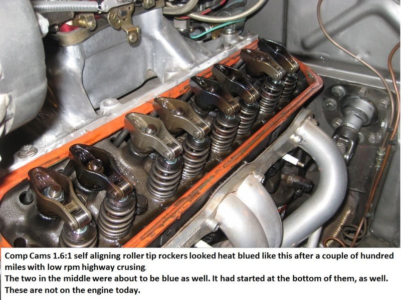
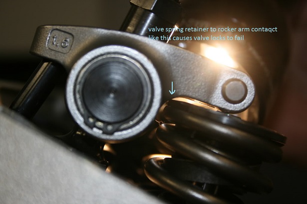
I did try 1.6 rockers for a short period last summer. Comp Cams stamped roller tip rockers. But they got blue from heat after a few hundred miles of low rpm highway driving.
(the two rockers in the middle was about to get blue, as well. It had started at the bottom on them. Wear marks looked normal. None of the push rods or rockers studs were damaged. These rockers should have more than big enough slot at the bottom for my lift).
Don't know if the miscoloration came from the small safety margins. I used Assembly lube durong the assembling.
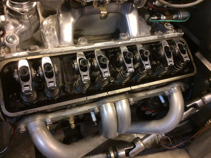
But I didn't like miscolorisation much, so I changed to PRW 1.5 ratio stainless full roller rockers.
Re: grinding down the spring pockets on Vortec heads?
Honestly, you SHOULD leave it as is. You are not going to see HUGE gains - more likely imperceptible.
If you really MUST run the 1.6 rockers, then Alex has valve locks that will increase your installed height by about .030". MEASURE, don't just go by the numbers. Give him a call and he can send you a pair of each for a low price. Then you can order the correct set once you have figured the ones you need. Be aware that ALL sets of locks and ALL sets of retainers and ALL sets of valves can vary quite a bit in their measurements. The valve seats vary also, especially if a valve job was done. It takes me many hours to set up heads because I compare every lock, every retainer, and every valve and then I do the math to make the combinations of parts that cancel out the machining tolerances so that my installed heights don't vary more than .005" across the head.
Make sure you currently have plenty of clearance between the top edge of the retainer and the bottom side of the rocker.
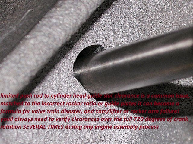
And you need to make sure your pushrods have enough clearance at their slots in the head. The higher ratio moves the pushrod in towards the stud.
Re: grinding down the spring pockets on Vortec heads?
Thank you for your answer.
All the numbers I use are measured.
The push rod holes are prepared for 1.6 rockers.
But you are probably right about how small differece it will make. And the present setup with the 1.5 rockers shold be both reliable and powerful.
I will leave it as it is.
Re: grinding down the spring pockets on Vortec heads?
Great reference photos N.E.84TA. Picture is worth a thousand words!
Two questions based on those.
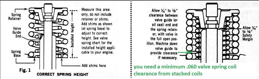
So checking coil bind...appears easy, right? I'm getting to the top of the lobe for that valve, then slipping a feeler gauge in between the coils and seeing what I have?
Trickier, clearance from the bottom of the retainer to the top of the seal. Seem obvious that with the spring compressed, I'm not reaching in to take any sort of physical measurement. So this is a calculation? Measure height from spring seat in head to top of seal before spring is installed...and measuring from the top of the retainer to the bottom of the retainer (retainer thickness) prior to install, Then assembling, top of the lobe like the coil bind check, then measure the top of the retainer down to the spring seat in the head on the outside?
Is a stainless ruler as a straight edge a dial caliper adequate for checking these dimensions?
Re: grinding down the spring pockets on Vortec heads?
Originally Posted by Hotrodder
.
I'm curious as to why they turned blue. If there is something fundamentally wrong that's preventing the rockers from getting oil, the roller rockers won't last long either.
Re: grinding down the spring pockets on Vortec heads?
Originally Posted by DynoDave43
Great reference photos N.E.84TA. Picture is worth a thousand words!
Two questions based on those.
So checking coil bind...appears easy, right? I'm getting to the top of the lobe for that valve, then slipping a feeler gauge in between the coils and seeing what I have?
Trickier, clearance from the bottom of the retainer to the top of the seal. Seem obvious that with the spring compressed, I'm not reaching in to take any sort of physical measurement. So this is a calculation? Measure height from spring seat in head to top of seal before spring is installed...and measuring from the top of the retainer to the bottom of the retainer (retainer thickness) prior to install, Then assembling, top of the lobe like the coil bind check, then measure the top of the retainer down to the spring seat in the head on the outside?
Is a stainless ruler as a straight edge a dial caliper adequate for checking these dimensions?
DD43, coil bind measuring, you are correct, I'm getting to the top of the lobe for that valve, then slipping a feeler gauge in between the coils and seeing what I have? You need at least .060" (total) extra clearance. If the spring had 6 coils, then that would be .010" between each. Using that method, you could keep inserting thicker and thicker feeler gauges until you "felt" the coils stack solid (assuming that you reached coil bind first and not the bottom of the retainer contacting the top of the valve seal). Then that would be your actual CB measurement.
Trickier, clearance from the bottom of the retainer to the top of the seal. Seem obvious that with the spring compressed, I'm not reaching in to take any sort of physical measurement. So this is a calculation? Measure height from spring seat in head to top of seal before spring is installed...and measuring from the top of the retainer to the bottom of the retainer (retainer thickness) prior to install, Then assembling, top of the lobe like the coil bind check, then measure the top of the retainer down to the spring seat in the head on the outside? I had to read this a couple of times, but I take it you are asking if you could take measurements and then do the math to get the R-S clearance. Answer: YES, but with the spring in it's pocket, it is difficult to get any measuring device in there - especially if the heads are installed on the block. A dial caliper is what is normally used to take these measurements. There are versions with, let's say, 2 half circles attached specifically for this purpose. But that tool can't be used with the spring in place. The best tool to use is a valve spring height mic. And, of course, the best time to take all of these measurements is BEFORE the head is assembled.
If your heads are already assembled and installed on the block, and even if the engine is in the car, and all you need to know is if you have enough safety margin (both CB & R-S clearance), then you could get .090" worth of feeler gauge between the rocker arm and valve tip (while on the cam lobe's base circle - no lift) and slowly rotate the engine BY HAND while watching to see if anything binds or makes contact.
Another method would be to rotate the engine to get a valve at max lift and find a way to use a lever to push down on the valve tip side of the rocker arm to see if you have enough additional clearance. If the engine is out of the car, you could use the dial caliper to get a measurement, but if the engine is in the car, then you will most likely have to estimate.
Last edited by NoEmissions84TA; 01-07-2019 at 01:01 AM.
Re: grinding down the spring pockets on Vortec heads?
Originally Posted by skinny z
I'm curious as to why they turned blue. If there is something fundamentally wrong that's preventing the rockers from getting oil, the roller rockers won't last long either.
So am I.
I checked that oil came via the push rods and out of the lubricant holes on the rockers.
Everything looked ok and it looked the same on all rockers arms.
I never really found out why this occured, or if it was "normal" or not.
Re: grinding down the spring pockets on Vortec heads?
From all the reading I've done - the bluing isn't from a lack of oil - it's a fundamental problem with friction rockers when used with that much lift, and the higher ramp rates of roller cams. It is claimed by many to be responsible for up to a 20-30 degree increase in oil temps. That's a lot of friction and the more lift you ask of them the hotter they get. I mean - is it any real surprise given how much power you can gain from full RR's (testing shows no significant difference with roller tip only)? 10-15 HP from full rollers means you are obviously freeing up a lot of loss due to friction. This problem is only made worse by the higher spring rates required for such cams. That's an insane amount of pressure.
FWIW I'm running PAC racing 130lb beehive springs, comp 787 rockers, low profile retainers, and Scorpion narrow body rockers on my Vortec heads. The LS6 springs were not a high enough seat pressure for the cam specs (Comp Nitrous HP cam .500/.520), and they did not fill well around the bosses on my Vortec heads.
GD
Last edited by GeneralDisorder; 01-07-2019 at 03:46 PM.
Re: grinding down the spring pockets on Vortec heads?
Interesting bit of info on the rocker arm overheating.
As a add-on to GD's post above:
My RHS Vortecs are fitted with the following:
Competition Cams 26918-16 Beehive Valve Spring. (125 @ 1.800 367 @ 1.150 .625" max lift)
Competition Cams 4705-16 Valve Spring I.D. Locators for 26918-16 Springs
Competition Cams 774-16 Steel Retainers for GM Gen III, 7 degree Angle for 26915 and 26918 Beehive Springs. (I've since upgraded to Comps tool steel retainer for a little more RPM headroom)
These heads are cut for a larger O.D. spring however the 26918 is ideally suited for my application. Max. lift hydraulic roller of .570". With the larger spring pockets, the I.D. locator was required.
(As you are all probably aware, the best thing about the conical (beehive) spring is the reduced seat pressure required to achieve the same results as a heavier spring due to the decreased mass of the spring and retainer assembly.)
EDIT: Imponte Ruiner? Hey GD. I had to look that one up.
Re: grinding down the spring pockets on Vortec heads?
Yeah I made a post about my graphics with a picture a while back.... The local radio station recently mentioned my car. I guess the morning show DJ drives by my shop frequently. It was referenced as "Bitchin graphics". LoL. People of the video game generation often recognize it and I've had quite a few kids take their picture with it. It's fun.
Re: grinding down the spring pockets on Vortec heads?
Originally Posted by GeneralDisorder
From all the reading I've done - the bluing isn't from a lack of oil - it's a fundamental problem with friction rockers when used with that much lift, and the higher ramp rates of roller cams. It is claimed by many to be responsible for up to a 20-30 degree increase in oil temps. That's a lot of friction and the more lift you ask of them the hotter they get. I mean - is it any real surprise given how much power you can gain from full RR's (testing shows no significant difference with roller tip only)? 10-15 HP from full rollers means you are obviously freeing up a lot of loss due to friction. This problem is only made worse by the higher spring rates required for such cams. That's an insane amount of pressure.
GD
I tend to agree, and that's why I changed to 1,5:1 full roller rockers.
But Comp Cams claim the roller tip rockers are ok up to 350 lbs open spring pressure, that is way more than mine. I have sent them the photo over asked for advice, but not received any answer.
Re: grinding down the spring pockets on Vortec heads?
A short update on this, and thank you so much for advices, tips & tricks I received from you during my many fussing posts about this engine project!
I choosed to keep the 1.5 roller rockers.
Followed the advice from a reputable engine shop, and changed to Dyno Cat mineral oil with lubricant additives. I showed them the photo of the blued rocker arms (see earlier posts), and they claimed it was because I had used syntetic oil intended for modern cars.
So far the engine works very well. Fires up at once, Pulls strong in the complete rpm range, yet still idles nice at app 750-800 rpms.
It really opens up from app 3000 rpm's.
L05 roller block with standard flat top pistons.
Vortec heads with beehvie springs from Alex's Parts.
PRW stainless self aligning 1,5 roller rockers.
Hardened push rods from Alex's Parts, standard length.
0,015 shim head gasket, to bump up the compression a bit. Should be app 9,9:1(?)
Edelbrock Air Gap intake.
Skip White HEI distributor with 1 slightly thinner spring on the centrifugal weigths to allow for a quicker sentrifual advance curve. Adjusted to app 30 degree full mecanical ignition advance.
Carb QFT 670 cfm w/mechanical secondaries, adjusted with wide band gauge.
T56 6-speed manual transmission from LT1 Camaro 1993-95.
4,09:1 rear axle ratio.
Rather big rear tires 275/45-18.
The best from two worlds. Quick accelration, yet still low rpm highway cruising.
Re: grinding down the spring pockets on Vortec heads?
I did a quick compression ratio check, both static and dynamic. The results are very similar to an overachieving Vortec headed 350 I built years back although our camshaft choices are very different.
Based on a few assumptions, notably the piston below deck value of .025" and the piston volume of 6 cc, at 10.1:1, that would be considered the limit on an iron head although there is some misinformation out there regarding what the SCR actually means to a running engine. Typically, you might see a response such as that it's too high for pump gas, etc. Things you may already know is that the real story is in the dynamic compression ratio. Sometimes called the running compression ratio . This is tied in to the cam spec. Specifically the intake valve closing point. Data suggests that a pump gas street engine should be somewhere in the 7.5 to 8.5:1 range for best performance, both in the output side and as a benefit, the fuel efficiency side. Fuel economy and compression ratio go hand in hand.
With a DCR of 8:1, you've avoided the "too high a compression ratio for iron heads" pitfall and the result is what you would expect. Decent performance.
Be sure you have the correct ignition timing under all conditions, (WOT, cruise, part throttle under load), and you'll have a overachiever as well.
Re: grinding down the spring pockets on Vortec heads?
Originally Posted by skinny z
I did a quick compression ratio check, both static and dynamic. The results are very similar to an overachieving Vortec headed 350 I built years back although our camshaft choices are very different.
Based on a few assumptions, notably the piston below deck value of .025" and the piston volume of 6 cc, at 10.1:1, that would be considered the limit on an iron head although there is some misinformation out there regarding what the SCR actually means to a running engine. Typically, you might see a response such as that it's too high for pump gas, etc. Things you may already know is that the real story is in the dynamic compression ratio. Sometimes called the running compression ratio . This is tied in to the cam spec. Specifically the intake valve closing point. Data suggests that a pump gas street engine should be somewhere in the 7.5 to 8.5:1 range for best performance, both in the output side and as a benefit, the fuel efficiency side. Fuel economy and compression ratio go hand in hand.
With a DCR of 8:1, you've avoided the "too high a compression ratio for iron heads" pitfall and the result is what you would expect. Decent performance.
Be sure you have the correct ignition timing under all conditions, (WOT, cruise, part throttle under load), and you'll have a overachiever as well.
8:1 DCR is 87 octane build to me especially with a good modern fast burn chamber and good quench. I was at 8.7:1 DCR from a 9.6:1 static with my iron Vortecs at one point. I might also add here that the GM Vortec 12cc dished pistons are horrible when it comes to quench effect. I once rebuilt a vortec and used flat top pistons and got the quench to 0.040" and found it had less detonation at 10.3:1 than the factory 9.4:1 engine had. With the stock pistons and tiny 395' marine cam I had to be careful with the total timing and the advance curve to keep from having detonation under heavy load on 93 octane. My current build will be an aluminum head 6" rod 383 with about 11:1 static and 9.07:1 DCR.
I am not overly worried about it though. My Nissan Titan was 9.6:1 static and 9.5:1 dynamic when the intake cams were phased 30� advanced at lower RPM. Intake cam was only 232 @ .006" and it advanced to a 94* ICL and 103* LSA when it was fully advanced. Fully retarded was a 124* ICL and 118* LSA. That engine was tuned to run 87 octane from the factory. At idle the intake cams were fully retarded but the instant you opened the throttle they went full advance. Once I tuned it for 93 octane it really woke up.
Re: grinding down the spring pockets on Vortec heads?
[QUOTE=Fast355;6314605]8:1 DCR is 87 octane build to me especially with a good modern fast burn chamber and good quench. I was at 8.7:1 DCR from a 9.6:1 static with my iron Vortecs at one point. QUOTE]
At 8.4:1 DCR, Vortec, flat top piston and .040" quench, I rattled like an SOB. That said, I was very aggressive on the timing particularly at part throttle cruise. Under light load, max timing was approaching 50 degrees and admittedly, that was too much. Even with 94 octane. That was with a mechanical distributor and vacuum advance combined.
What would your timing curve have been like?
Re: grinding down the spring pockets on Vortec heads?
[QUOTE=skinny z;6314606]
Originally Posted by Fast355
At 8.4:1 DCR, Vortec, flat top piston and .040" quench, I rattled like an SOB. That said, I was very aggressive on the timing particularly at part throttle cruise. Under light load, max timing was approaching 50 degrees and admittedly, that was too much. Even with 94 octane. That was with a mechanical distributor and vacuum advance combined.
What would your timing curve have been like?
I started with 10� up to 1,200 rpm, between 1,200 and 2,400 rpm the timing smoothly ramped up to 22�, from 2,400 to 3,600 I smoothly ramped up to 26�, from 3,600-5,200 it slowly advanced to 30�. Idle was about 24� @ 750 rpm. Cruising on level ground at 2,400 rpm at 75 mph in OD about 38� total at 12 in/hg vacuum. At 3,200 rpm (75 mph in 3rd gear) it would pull about 15-16 in/hg and the timing was about 42�. As load increased at cruising speed I smoothly retarded the timing down to the WOT timing. I will say being able to program what you want at any rpm or load into a timing map allows you to really get the timing advamce dialed in. On 93 octane it would take and wnjoyed a few degrees more timing. Most of the cells were 2-6� higher. 32� total at WOT and 2-4� more thought the lower rpm values but the advance numbers were about 6� higher at light load up to about 48� total. In the rare event it did knock the knock sensor could pull up to 12� of timing to prevent detonation.
Sorry for the delay in posting. I spent my afternoon installing the crankshaft in my new 383 build. Lots of measuring for bearing clearances and other details. On the plus side this build is using a summit racing block and a scat crank. Between the two companies the main bearing oil clearance ended up at 0.0025 in every journal with standard size King bearings and the thrust clearance is spot on. Not exactly happy with how summit advertises the block they sell but I believe it will work just fine. They say it is a GM 4-bolt block but in reality it is a 2-bolt block with some kind of chinese 4 bolt conversion cap and straight outer bolts. I know it is a conversion because the caps are marked with the manufacturer and they are stepped to fit into the 2 bolt block main cap registers. Otherwise the machine work is about perfect and I cannot even tell that the block was ever a used block. I just had to do a little cleanup work to bring it up to my standard of cleanliness for a fresh build. And a couple of other things, such as debur the rear main cap oil pump opening and smooth the oil pump inlet.
Re: grinding down the spring pockets on Vortec heads?
Yep. The laptop sure beats my old school approach to timing tuning. Aside from the springs and weights for the centrifugal advance, there's also the two tuning parts for vacuum with both advance onset vacuum value as well as the total advance available. Throw in a third function if you want to include ported or full manifold vacuum for control. And the workings are somewhat labour intensive. I tie down the advance springs to keep the mechanical part out of the picture while I work the various vacuum components with a Mityvac. This is vital when using full manifold vacuum and trying to tune the idle. The results I'll say are quite remarkable though. With 288 of advertised cam timing, this 355 idles like a watch. Mileage is pretty good too with a respectable 21(US)MPG highway result.
As for your 383 build, maybe start a new thread for that one (if you haven't already). I too am collecting parts to build an all forged 383 using my existing RHS Vortec heads (worked over by one of the local engine shops) and a cam I've yet to spec. I'd be interested in discussing what your goals are and how you're going about it. In as much as I'd like pick my own parts, (Lunati Sledgehammer crank, Scat's 6" stroker cap screw rods, and a piston that'll let me build towards 10:1 static compression while using a 64cc head and maintaining that .040" quench we've discussed (probably a D-shaped dish like those offered by Ross and others), it may be that I get GMs HT383 shortblock and call it a day. The external balance of GM's offering concerns me somewhat as that puts a lot of stress on the crank and this lump will likely see some open road events, road racing (the dragstrip and road course are 20 minutes from my house) or a flying mile somewhere. I've some excellent build insights from the likes of Vizard and how a small 170/180cc cylinder head can work with a longer duration cam and give exactly the results I'm looking for. Mathematically, 180cc isn't likely to produce 500HP but one can get pretty close while keeping maximum engine speeds in check.
Anyway, thanks to OP for the loan of the thread. Hope he has things sorted out.
 01-01-2019, 10:28 AM