

Long story short I bought a monster transmissions external lockup kit for my 700r two wire solenoid setup. Then I realized I am one of the lucky few who DO NOT have an EXTERNAL 4th gear test port machined into my 700rs body. So I need an INTERNAL kit but cant return this kit (lost receipt). Monster is saying they dont have any internal kits . So I want to use my external kit inside instead.
I took an ohms reading last night and got 24 ohms so I am assuming the solenoid is good.
Could I just take the two contact pressure switch from the external monster kit - put it in the 4th gear valve body port inside the trans . Run one wire from one switch post to gnd and the other directly to the ground black wire of the 2 wire solenoid ? As I understand it GROUND is switched in to activate the solenoids normally . Is that correct ?
What about bypassing the temp switch ? How do I bypass those wires ?
I assume I can just use my existing factory tranny external plug and harness with no mods to that ?
Here is a pic can someone mark this up and or help or just tell me what to do ?

Senior Member
What serial number is your transmission? There's several ways they were wired up from the factory, so it would help look up the correct diagram. Alternatively if you map it out that would work too. Hooking it up internally shouldn't be too difficult once we know the current wiring. More experienced members could probably figure it out without a diagram, but I don't trust my memory 
Thanks for the reply. I REALLY got out there last night and tried to understand it all with a volt meter in hand etc. and think I figured it out.
What I learned is the 4th gear oil pressure switch in my 1991 700R tranny is normally open . I assume when you hit 4th gear that 1 post switch shorts to ground (via the valve body).
The +12 wire in the factory harness - on the side of the transmission into my 1991 RS tranny is Purple .
The internal Brown wire in the pan brings that purple +12 over to the solenoid.
The Black pan wire is to the solenoids ground.
So I cut the brown wire with green connector wire about 3 inches long that normally goes to the 4th gear switch and tied it directly to the black solenoid wire. I then heat shrinked it .
So +12 Purple from outside the trans will supply +12 to the brown solenoid wire all the time . When the 4th gear pressure switch closes to valve body ground the solenoid will be grounded via the 4th gear oil pressure switch and the black wire running over to the solenoid.
I cut two of the three wires in the transmissions outside connector going back to the ECM as they aren't needed and I didnt want them in the equation.
As far as the temperature switch inside the pan -electrically he isn't part of "my" activation circuit anymore but I left him and his wires connected in the pan - figured its not going to hurt anything.
To get my +12 to open circuit wise if I slam on the brakes suddenly or floor it to downshift and unlock the converter I found that old corvettes have a combo vacuum switch / brake pedal switch. So I am going to get one of those and try to mount it to my brake pedal and supply it with an 1/8th inch vacuum hose connected to the manifold and the trans +12 wire.
I HAVE NOT DRIVEN THE CAR YET WITH THESE MODS - will let you all know if it works or not tonight - pretty sure it will .


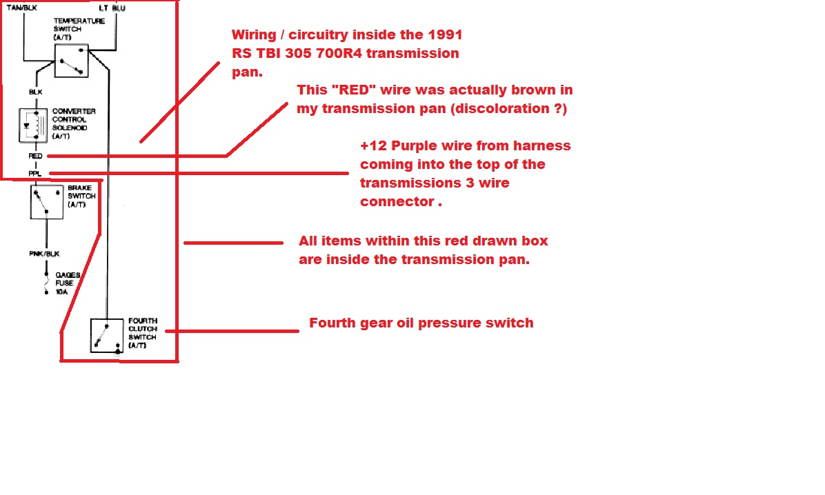
My 91 r/s 305 was equipped with a two wire solenoid marked "red" , "blk". The "red" terminal is actually a brown wire . I don't know if it tarnishes over time or what.
Clarified picture.....

Here is the "factory" wiring diagram snippet for the TCC circuit in the 1991 RS TBI 305 700R AUTO . As you can see I should get +12 interrupted to the TCC solenoid by the brake pedal application because I didnt modify that section of the circuitry ! So if I hit my brakes the torque converter "should" unlock immediately.
The second drawing is how I modified the circuitry to work with no ECM.
The second drawing is how I modified the circuitry to work with no ECM.
It works as I wired it 