Do away with dizzy?

 08-15-2009, 12:38 PM
#152
 08-15-2009, 01:20 PM
#153
Supreme Member

iTrader: (1)

Join Date: Jan 2002
Location: garage
Posts: 4,432
Likes: 0
Received 1 Like
on
1 Post
Engine: 3xx ci tubo
Transmission: 4L60E & 4L80E
Re: Do away with dizzy?
Post #143 says:
The thickness of the trigger wheel is 4/15'th of a inch. The diameter of the trigger wheel is about 6 & 15/16 inches. Sorry about the weird numbers I left my measuring caliper at home and am using 1/60 engineering scale engineering ruler.
The PDF file at that site has a diameter of 6 & 5/16.
Which is correct?
08-15-2009, 01:24 PM
#154
Supreme Member
iTrader: (1)
Join Date: Jan 2002
Location: garage
Posts: 4,432
Likes: 0
Received 1 Like
on
1 Post
Engine: 3xx ci tubo
Transmission: 4L60E & 4L80E
Re: Do away with dizzy?
I wonder how much it affects the balance at the crank snout. It sounded liked he recessed the balancer. Did he have it machine 1/4" shorter to make up for the 1/4" wheel?
EDIT: I looked at the files and they give the dimensions. I think I might know someone with a Northstar crank to verify. My balancer is 8" so I will have to resize anyway. Using the values in this thead it comes out to about 1* for a 1/16".
Last edited by junkcltr; 08-15-2009 at 02:03 PM.
08-15-2009, 06:11 PM
#155
Supreme Member
iTrader: (1)
Join Date: Jan 2002
Location: garage
Posts: 4,432
Likes: 0
Received 1 Like
on
1 Post
Engine: 3xx ci tubo
Transmission: 4L60E & 4L80E
Re: Do away with dizzy?
The other thing that probably needs to change in the BIN is the spark latency table. Since the various HEI modules have a different latency then the DIS module is probably different.
This only bin changes I see that need to be done so far for the $8D is:
This only bin changes I see that need to be done so far for the $8D is:
Code:
L8025:        .byte   0x11            ;INITAL SPK ADV, 6 DEG,
L8026:        .byte   0x00,0x77       ;39 DEG, (MAX SA ADD TO INIT TMG)
L8028:        .byte   0xFF,0xF5       ;65525d (MAX SA RETARD FOR KNOCK) 3.5 DEG

;-------------------------------------------------------------------
;              SPARK LATENCY CORRECTION TABLE (USEC)
;              Spark Vs RPM and MAP
;                 TBL = VAL/15.26
;-------------------------------------------------------------------
;            Value (Hex)     Usec     RPM
;----------------------------------------------------
L8129:  .byte     0x0E     ; 213.6     800  RPM
        .byte     0x12     ; 274.7    1200  RPM
        .byte     0x14     ; 305.2    1600  RPM
        .byte     0x10     ; 244.2    2000  RPM
        .byte     0x12     ; 274.7    2400  RPM
        .byte     0x10     ; 244.2    2800  RPM
        .byte     0x14     ; 305.2    3200  RPM
        .byte     0x15     ; 320.5    3600  RPM
        .byte     0x13     ; 289.9    4000  RPM
        .byte     0x14     ; 305.2    4400  RPM
        .byte     0x14     ; 305.2    4800  RPM
        .byte     0x14     ; 305.2    5200  RPM
        .byte     0x14     ; 305.2    5600  RPM
        .byte     0x14     ; 305.2    6000  RPM
Last edited by junkcltr; 08-15-2009 at 06:20 PM.
08-15-2009, 10:27 PM
#156
Supreme Member
iTrader: (1)
Join Date: Jan 2002
Location: garage
Posts: 4,432
Likes: 0
Received 1 Like
on
1 Post
Engine: 3xx ci tubo
Transmission: 4L60E & 4L80E
Re: Do away with dizzy?
Here is what I found. If you look at the timing waveform at:
http://www.lukeskaff.com/car/northstar/theory.html
you will see that the falling edge of the 4x signal is 70* before the next TDC. That 70* is the 10*_base_timing + 60*_ref_angle
Since the $8D doesn't have the typical ref_angle constant then it must be included in the base_value which is the initial timing constant.
address L8025: goes from a value of 6* to a value of 10*+60* = 70*
Suppose the desired timing is 59* BTDC at the crank after all the table lookups. Suppose the DIS has a ref_angle of 60* and an initial/base advance of 10*. The total initial/base is 10+60 = 70*. This base/initial angle of 70* is seen in the timing waveforms.
Then 59* - 70* = -11* is computed in the ECM. The ECM would then do L8026 - (-11*) which is -10 - (-11) = 1* which is greater than 0*........so the spark is not limited. So, in order not to limit spark advance then timing > constant. Wanting a max timing of 39* like the stock dizzy would require (MAX_ADV - (TOTAL-INITIAL)) > 0
Using the desired stock 39* of advance yields a MAX_ADV value of (-30 - (39-70)) > 0 or (-30 + (31)) > 0 or 1 > 0
As you can see, the DIS doesn't have the (39+6) = 45*spark advance limitations of the dizzy.
The retard value is done using (MAX_RTRD - (TOTAL-INITIAL)) < 0.
If the result is greater than or equal to zero then clamping is done (spark is limited)
Using the above values with a max. retard of -70 gives
(-70) - (59 - 70) = -70 -11 = -81* which is less than zero, no clamp is done
Using the stock $8D value for retard and say 20* of timing (idle) with the DIS offset gives
(-3.5) - (20-70) = -3.5 - (-50) = 46.5* which is GREATER THAN ZERO and clamping is done
This is why things go wrong when the MAX_RTRD is not changed properly.
This is the max. retard value using the so called proper values.
(-70) - (1 - 70) - = -70 + 69 = -1* so all is good, no clamp is done
The Max retard is 1* and not 3.5* like in a stock $8D bin
Using a MAX_RTRD value of -67.5* would make the max retard like the stock $8D
(-67.5*) - (3.5 - 70) - = -67.5 + 66.5 = -1
If you want the same spark advance value as the $8D you would enter the following:
L8025: 70* decimal
L8026: -30* decimal gives a max advance of 39*
L8028: -67.5* decimal gives a max retard of 3.52*
The values below are for the "standard" DIS module and are the values I would use from what the timing waveforms show:
L8025: 70* decimal
L8026: -10* decimal gives a max advance of 59*, VALUE = (desired_max_adv - initial_adv) + 1
L8028: -70* decimal gives a max retard of 1*, VALUE = (desired_retard - initial_adv)
These values are for the $8D bin.
Note that the values I posted are different than what RBob posted earlier in this thread. These are the values from post #143
L8025: 60* decimal
L8026: -10* decimal gives a max advance of 69*, VALUE = (desired_max_adv - initial_adv) + 1
L8028: -70* decimal gives a max retard of 10*, VALUE = (desired_retard - initial_adv)
The max. retard seems a little high to me. This is better for the non-$8D codes that include both an initial constant and a ref_angle constant. Together
the two constants add up to about 70* like shown earlier.
So there is the code stuff.......all done using a disassembled bin. Now to get some trigger wheels made. Like mentioned earlier in this thread....this would work great on the LT1 intake swaps and the LT1 engines. I think this is an easy change in the $0D code also. I will have to take a look. DIS along with the E-trans would be nice. Gotta do the spark rev limit mod. though because the revs come up fast when the tires break loose from boost. Pulling spark and adding fuel is a crutch for a real spark rev limiter.
On a side note, I think this setup is better than a 411 PCM. The reason being is that the $0D code can easily be adapted to boost, N2O pulsewidth injection (variable N2O), water/alky motor PWM, extra IATs, oil temp sensor, wastegate control. The list goes on and on. This can't easily be done with the new 411 and up PCMs. Not to mention that those PCMs require $500 and up just to tune ONE of them and a lot of the calibration tables are missing. The $0D can be easily modified to send out new variables on the ALDL. Again, not easily done on the 411 and up ECMs. The only thing the newer ones have going for them is SEFI. Until the tuning gets cheaper or I need a new project it is OBD-I for me. I can live without the SEFI and just run a tad richer so the leaner cyls are happy.
http://www.lukeskaff.com/car/northstar/theory.html
you will see that the falling edge of the 4x signal is 70* before the next TDC. That 70* is the 10*_base_timing + 60*_ref_angle
Since the $8D doesn't have the typical ref_angle constant then it must be included in the base_value which is the initial timing constant.
address L8025: goes from a value of 6* to a value of 10*+60* = 70*
Code:
; SUB OFF SPK INITAL ADVANCE
;
LBB47:        subb    L8025                   ; 6 DEG REF SPK ANGLE                   ; CRef: 0xBB40
              sbca    #0x00
              std     *L00BB                  ; SPK ADV Rel to DRP, (un-lim)
;
; LIMIT SPK ADV TO 40 DEG
;
              ldd     L8026                   ; 39 DEG, (MAX ADDED SA LMT)
              subd    *L00BB                  ; SPK ADV Rel to DRP, (UN-LIM)
              bgt     LBB59                   ; Branch If Greater Than..
                                              ;...else
              addd    *L00BB                  ; SPK ADV Rel to DRP, (UN-LIM)
std *L00BB ; Save NEW SPK ADV Rel to DRP, (UN-LIM) Then 59* - 70* = -11* is computed in the ECM. The ECM would then do L8026 - (-11*) which is -10 - (-11) = 1* which is greater than 0*........so the spark is not limited. So, in order not to limit spark advance then timing > constant. Wanting a max timing of 39* like the stock dizzy would require (MAX_ADV - (TOTAL-INITIAL)) > 0
Using the desired stock 39* of advance yields a MAX_ADV value of (-30 - (39-70)) > 0 or (-30 + (31)) > 0 or 1 > 0
As you can see, the DIS doesn't have the (39+6) = 45*spark advance limitations of the dizzy.
The retard value is done using (MAX_RTRD - (TOTAL-INITIAL)) < 0.
If the result is greater than or equal to zero then clamping is done (spark is limited)
Using the above values with a max. retard of -70 gives
(-70) - (59 - 70) = -70 -11 = -81* which is less than zero, no clamp is done
Using the stock $8D value for retard and say 20* of timing (idle) with the DIS offset gives
(-3.5) - (20-70) = -3.5 - (-50) = 46.5* which is GREATER THAN ZERO and clamping is done
This is why things go wrong when the MAX_RTRD is not changed properly.
This is the max. retard value using the so called proper values.
(-70) - (1 - 70) - = -70 + 69 = -1* so all is good, no clamp is done
The Max retard is 1* and not 3.5* like in a stock $8D bin
Using a MAX_RTRD value of -67.5* would make the max retard like the stock $8D
(-67.5*) - (3.5 - 70) - = -67.5 + 66.5 = -1
If you want the same spark advance value as the $8D you would enter the following:
L8025: 70* decimal
L8026: -30* decimal gives a max advance of 39*
L8028: -67.5* decimal gives a max retard of 3.52*
The values below are for the "standard" DIS module and are the values I would use from what the timing waveforms show:
L8025: 70* decimal
L8026: -10* decimal gives a max advance of 59*, VALUE = (desired_max_adv - initial_adv) + 1
L8028: -70* decimal gives a max retard of 1*, VALUE = (desired_retard - initial_adv)
These values are for the $8D bin.
Note that the values I posted are different than what RBob posted earlier in this thread. These are the values from post #143
L8025: 60* decimal
L8026: -10* decimal gives a max advance of 69*, VALUE = (desired_max_adv - initial_adv) + 1
L8028: -70* decimal gives a max retard of 10*, VALUE = (desired_retard - initial_adv)
The max. retard seems a little high to me. This is better for the non-$8D codes that include both an initial constant and a ref_angle constant. Together
the two constants add up to about 70* like shown earlier.
So there is the code stuff.......all done using a disassembled bin. Now to get some trigger wheels made. Like mentioned earlier in this thread....this would work great on the LT1 intake swaps and the LT1 engines. I think this is an easy change in the $0D code also. I will have to take a look. DIS along with the E-trans would be nice. Gotta do the spark rev limit mod. though because the revs come up fast when the tires break loose from boost. Pulling spark and adding fuel is a crutch for a real spark rev limiter.
On a side note, I think this setup is better than a 411 PCM. The reason being is that the $0D code can easily be adapted to boost, N2O pulsewidth injection (variable N2O), water/alky motor PWM, extra IATs, oil temp sensor, wastegate control. The list goes on and on. This can't easily be done with the new 411 and up PCMs. Not to mention that those PCMs require $500 and up just to tune ONE of them and a lot of the calibration tables are missing. The $0D can be easily modified to send out new variables on the ALDL. Again, not easily done on the 411 and up ECMs. The only thing the newer ones have going for them is SEFI. Until the tuning gets cheaper or I need a new project it is OBD-I for me. I can live without the SEFI and just run a tad richer so the leaner cyls are happy.
Last edited by junkcltr; 08-16-2009 at 12:38 AM.
08-16-2009, 12:59 AM
#157
Supreme Member
iTrader: (1)
Join Date: Jan 2002
Location: garage
Posts: 4,432
Likes: 0
Received 1 Like
on
1 Post
Engine: 3xx ci tubo
Transmission: 4L60E & 4L80E
Re: Do away with dizzy?
The latency table thing. The $8D and other bins using a HEI module dizzy have this table.
For the $8D at 3200 RPM the latency table is 305usec
At 3200 RPM that is 18750us or 52usec/crank_degree
So 305/52 is about 6* of timing advance change due to HEI module delay.
At 6000 RPM the $8D also has 305usec. This is 10000us/360 = 28usec/degree.
305/28 = 11* degree of timing advance.
So if the DIS doesn't have the latency like an HEI then you could be up to 11* advanced if using the stock $8D table.
08-16-2009, 02:49 PM
#158
Junior Member

Join Date: Jul 2007
Location: largo, Fl
Posts: 22
Likes: 0
Received 0 Likes
on
0 Posts
Car: 93 Z28
Engine: LT1 w/ 727ecm, $59, N* coil packs
Transmission: 6 gear
Axle/Gears: 3.73
Re: Do away with dizzy?
no. I just downloaded a cad reader and printed it off of that. I did a layout of the wheel based on the drawing, and transferred my layout to a piece of 3/16 steel.
08-16-2009, 07:40 PM
#159
Re: Do away with dizzy?
well we spent over 4 hours trying to get the ecm to control the timing right. burnt over 40 bin files and nothing even came close. I tried the max retard and max adv way, and the work around of adding a bunch of timing thru different bais's and spark maps. nothing worked or seemed to make any sense. I would get it within 10ish * at idle of comanded and then any way I went with any value would make it jump 40* in any way it felt like it. at this point I need a week to regroup, go thru my notes I made along the way and hope something makes sense cause right now I'm questioning if this can even be done. other than that, the car runs fine with the bypass wire pulled and running on base timing. needs the tune cleaned up a bit, but drivable. blah
08-16-2009, 08:11 PM
#160
Re: Do away with dizzy?
well we spent over 4 hours trying to get the ecm to control the timing right. burnt over 40 bin files and nothing even came close. I tried the max retard and max adv way, and the work around of adding a bunch of timing thru different bais's and spark maps. nothing worked or seemed to make any sense. I would get it within 10ish * at idle of comanded and then any way I went with any value would make it jump 40* in any way it felt like it. at this point I need a week to regroup, go thru my notes I made along the way and hope something makes sense cause right now I'm questioning if this can even be done. other than that, the car runs fine with the bypass wire pulled and running on base timing. needs the tune cleaned up a bit, but drivable. blah
Last edited by Six_Shooter; 08-16-2009 at 08:57 PM.
08-17-2009, 08:41 AM
#161
Re: Do away with dizzy?
08-17-2009, 08:59 AM
#162
Senior Member

Re: Do away with dizzy?
The N* DIS module should run with 2 out of 3 of the signals present. So if you have both of the crank signals, it should be OK. http://www.cadillacforums.com/forums...93-99-dis.html You are likely fighting with something in the program...
08-17-2009, 12:35 PM
#163
TGO Supporter

Join Date: Aug 2001
Location: NJ/PA
Posts: 1,008
Likes: 0
Received 0 Likes
on
0 Posts
Car: Yes
Engine: Many
Transmission: Quite a few
Re: Do away with dizzy?
there is one thing that I don't think has been mentioned, and this might be why you have issues getting it to run, ???, in the diy-efi post it mentions that the numbers are
2's-complement, since they are negative numbers. You might not be putting the right values in. Since I have very limited knowledge with respect to the code, I'm not sure what the actual values should be. Rbob or Junk might be able to shed some light.
2's-complement, since they are negative numbers. You might not be putting the right values in. Since I have very limited knowledge with respect to the code, I'm not sure what the actual values should be. Rbob or Junk might be able to shed some light.
08-17-2009, 12:48 PM
#164
Supreme Member
iTrader: (1)
Join Date: Jan 2002
Location: garage
Posts: 4,432
Likes: 0
Received 1 Like
on
1 Post
Engine: 3xx ci tubo
Transmission: 4L60E & 4L80E
Re: Do away with dizzy?
I will take a look at the $8D again. ???, what values did you enter for the timing in the bin?
The V6 DIS module latency is 153 usec. I would set the $8D latency vs. RPM table to use 153 usec for all RPMs to start.
The V6 DIS module latency is 153 usec. I would set the $8D latency vs. RPM table to use 153 usec for all RPMs to start.
Last edited by junkcltr; 08-17-2009 at 01:16 PM.
08-17-2009, 02:22 PM
#165
Re: Do away with dizzy?
I don't have my laptop in front if me, but the values and locations Rbob posted above. I also found a said to be working v6 .bin and .xdf using dis $8D to check that I had the s_apju xdf defined right. after I made the changes I double checked the hex numbers thru tunerpro and they matched what Rbob posted. so I felt the formulas are right, just with the 2swhatever it allows you to type in any number, even if it doesn't fit within -90 to 90. for retard and adv but as long as you know that's the min and max, it seems to work judging by the hex numbers. I also tried the other way, which you make up the 60* timing of the dis with timing in the bin.(and rasing the max advanced as well) like the bias and coolant tables. a few guys on code59 have got to work. and that didn't work for me either. he made some hardware changes after I left to how the sensor mount in relation to the crank wheel. and we are going to try again.
08-17-2009, 02:57 PM
#167
Supreme Member
iTrader: (1)
Join Date: Jan 2002
Location: garage
Posts: 4,432
Likes: 0
Received 1 Like
on
1 Post
Engine: 3xx ci tubo
Transmission: 4L60E & 4L80E
Re: Do away with dizzy?
The values RBob gave neglected the 10* of initial advance. I think you need 60+10 = 70* for L8025. That is a value of 0xC7.
Why is playing with the two crank sensor locations? The diagram shows exactly where to put the sensors. You can't move them. If you do then the base timing will be moved and the bin initial value must be moved.
Are the crank sensors wired right? polarity?
Why is playing with the two crank sensor locations? The diagram shows exactly where to put the sensors. You can't move them. If you do then the base timing will be moved and the bin initial value must be moved.
Are the crank sensors wired right? polarity?
08-17-2009, 04:04 PM
#168
Moderator
iTrader: (1)

Join Date: Mar 2002
Location: Chasing Electrons
Posts: 18,401
Likes: 0
Received 215 Likes
on
201 Posts
Car: check
Engine: check
Transmission: check
Re: Do away with dizzy?
As an example for a DIS set up running at 60* BTDC initial timing, here are the values:
???, did you have a chance to put a timing light on the damper with the engine running? First with the bypass open, then with the ECM in charge of the timing? That will tell alot about what is going on.
RBob.
08-17-2009, 04:18 PM
#169
Supreme Member
iTrader: (1)
Join Date: Jan 2002
Location: garage
Posts: 4,432
Likes: 0
Received 1 Like
on
1 Post
Engine: 3xx ci tubo
Transmission: 4L60E & 4L80E
Re: Do away with dizzy?
I think some might get confused with comparing the $A1 to the $8D because the $A1 does an initial of 10* and a ref angle of 60*. The $8D just has the initial which must be 70*.
Last edited by junkcltr; 08-17-2009 at 04:24 PM.
08-17-2009, 04:25 PM
#170
Moderator
iTrader: (1)
Join Date: Mar 2002
Location: Chasing Electrons
Posts: 18,401
Likes: 0
Received 215 Likes
on
201 Posts
Car: check
Engine: check
Transmission: check
Re: Do away with dizzy?
And if the timing was off by 10*, it wouldn't cause the engine to have all sorts of problems running.
To ???, besides the timing light, did you get a data log? The ALDL spits out what the ECM is setting for timing. The converted values may not make sense, but we can convert from the raw.
I agree with the week off to re-group. BTDT and it does help.
RBob.
 08-17-2009, 06:45 PM
#172
Re: Do away with dizzy?
wow, thinks for the replys guys. i had missed some when i looked thru last night.
as for data logging, i didn't record anything, but i did have it open and watching real time. TP was showing normal looking timing that was commanded in the bin. lt1 spark tables, 25ish idle, 41ish reved to around 1500.
let me read and reread this a few times and i'll try to understand it and also answer the few questions. just wanna make sure i'm answering them with what really happened. because we thru a ton of different things at it. moving min and max spark around quite a bit. also thanks for the part about needing to add the 10* base to the reference. now that i've read it, i remember hearing something about other dis codes having a space to plug that in but i didn't understand it at the time.
what do you guys think of this idea? its from another post on another board. but if it works, it may clear some stuff up.
i also downloaded that $A1 bin and xdf from the link above about running a northstar motor on a 730ecm. its said to be a running bin. so if i load it up, and it works. atleast thats a start. if that doesn't work. something is out of wack.
as for data logging, i didn't record anything, but i did have it open and watching real time. TP was showing normal looking timing that was commanded in the bin. lt1 spark tables, 25ish idle, 41ish reved to around 1500.
let me read and reread this a few times and i'll try to understand it and also answer the few questions. just wanna make sure i'm answering them with what really happened. because we thru a ton of different things at it. moving min and max spark around quite a bit. also thanks for the part about needing to add the 10* base to the reference. now that i've read it, i remember hearing something about other dis codes having a space to plug that in but i didn't understand it at the time.
what do you guys think of this idea? its from another post on another board. but if it works, it may clear some stuff up.
If you have a method of measuring delivered timing, you can mechanically check the timing offset required by the DIS system. By connecting the REF to the EST line and applying 5V to the bypass line, you cause the ICM to deliver a spark pulse back to itself. Using an advance type light and cranking the engine you can measure the spark offset. Keep in mind the ecm must be disconnected for this test.
i also downloaded that $A1 bin and xdf from the link above about running a northstar motor on a 730ecm. its said to be a running bin. so if i load it up, and it works. atleast thats a start. if that doesn't work. something is out of wack.
08-17-2009, 08:27 PM
#173
Re: Do away with dizzy?
ok, dumb question about location and tunerpro xdf's.
so the location of the values are this.
L8025:
L8026:
L8028:
take max retard, i highlight, hit F2 and edit box pops up. for address it says address(hex) 28.(which doesn't seem like a hex number to me) and when i hit the summarys list, and scroll down to max retard. it shows 28--->29 under location. where's my L80 at? because under summary the spark ret,max for knock lists the same 28--->29(happened to be right under max retard) as its location. i know these both can't be the same. how would i check that i have the location right. as in L8028?
just trying to cover everything i don't fully understand.
i feel like a max retard
08-17-2009, 09:36 PM
#174
08-17-2009, 09:42 PM
#175
Supreme Member
iTrader: (1)
Join Date: Jan 2002
Location: garage
Posts: 4,432
Likes: 0
Received 1 Like
on
1 Post
Engine: 3xx ci tubo
Transmission: 4L60E & 4L80E
Re: Do away with dizzy?
ok, dumb question about location and tunerpro xdf's.
so the location of the values are this.
L8025:
L8026:
L8028:
take max retard, i highlight, hit F2 and edit box pops up. for address it says address(hex) 28.(which doesn't seem like a hex number to me) and when i hit the summarys list, and scroll down to max retard. it shows 28--->29 under location. where's my L80 at? because under summary the spark ret,max for knock lists the same 28--->29(happened to be right under max retard) as its location. i know these both can't be the same. how would i check that i have the location right. as in L8028?
just trying to cover everything i don't fully understand.
i feel like a max retard
so the location of the values are this.
L8025:
L8026:
L8028:
take max retard, i highlight, hit F2 and edit box pops up. for address it says address(hex) 28.(which doesn't seem like a hex number to me) and when i hit the summarys list, and scroll down to max retard. it shows 28--->29 under location. where's my L80 at? because under summary the spark ret,max for knock lists the same 28--->29(happened to be right under max retard) as its location. i know these both can't be the same. how would i check that i have the location right. as in L8028?
just trying to cover everything i don't fully understand.
i feel like a max retard
For the $8D XDF file you want the following:
address data
0025 70_decimal (0xC7 hex) which is 70*
0026 0xFF
0027 0xE4
0028 0xFF
0029 0x39
08-17-2009, 10:00 PM
#176
Re: Do away with dizzy?
and i did try adding 10* to Rbob's values he gave me because most people did say 70* is the ref for the n*. but i didn't do the math right lol. looking back i did burn something close to right thou lol. still didn't work.
oh and i think i found the address of the min,max, ref in the $A1 above that's said to run the northstar motor. and came up with
rev at $801B. 65*
max adv at $8023. -6.33*
min retard at $8025. -54.84*
i wanted to look up the spark latency setting, but its not defined and i haven't done a search yet. i'm guessing i have to find a disassemble of A1 and see if someone commented it. which is over my head lol
08-17-2009, 10:10 PM
#177
Supreme Member
iTrader: (1)
Join Date: Jan 2002
Location: garage
Posts: 4,432
Likes: 0
Received 1 Like
on
1 Post
Engine: 3xx ci tubo
Transmission: 4L60E & 4L80E
Re: Do away with dizzy?
from the $A1 code
address 8021 shows the 153 usec latency correction. It appears it is always constant for the DIS. The $8D dizzy HEI module has a table that varies.
The "0x" means that the number is being displayed as a hex number.
address 8021 shows the 153 usec latency correction. It appears it is always constant for the DIS. The $8D dizzy HEI module has a table that varies.
The "0x" means that the number is being displayed as a hex number.
Code:
8013        1A     26 KINITSPK  9 DEG    INITIAL SPARK ADVANCE

801B        AA    170 KREFANGL 59.8 DEG SPARK REFERENCE ANGLE

8021      000A     10 KTIMELAG       153 USEC TIME DOMAIN CORRECTION TO SPARK
8023      FFE4  65508 KMAXADV2       -10 DEG  MAX ADVANCE REL TO REF (2'S COMP)
8025      FF39  65337 KMAXRTD2       -70 DEG  MAX RETARD REL TO REF (2'S COMPL)
Last edited by junkcltr; 08-17-2009 at 10:14 PM.
08-19-2009, 01:34 PM
#180
Senior Member
Re: Do away with dizzy?
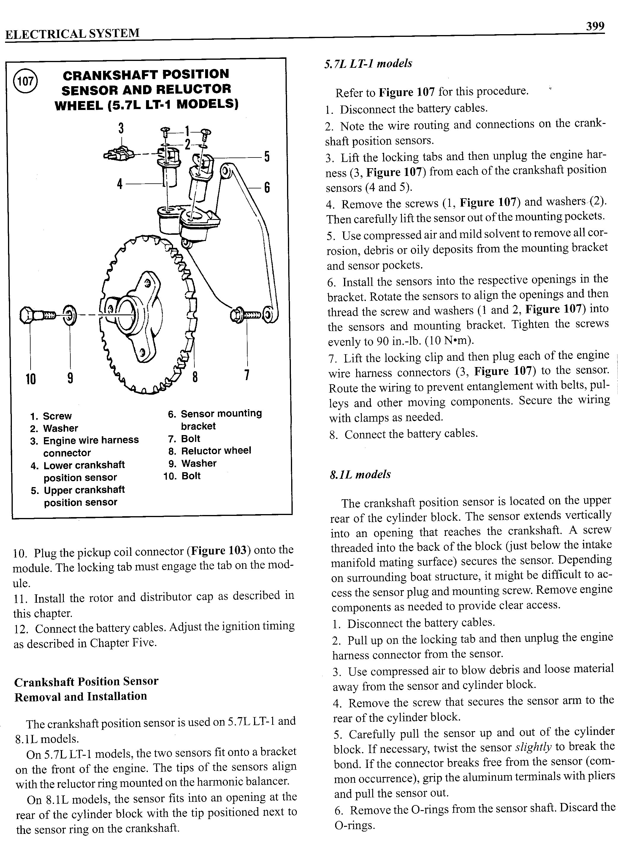
For those of you considering using the northstar DIS system, I just dug up some interesting information.
Indmar, a marine engine company, "marine-ized" the LT-1 engine back in the 1990s. They did so by mounting a reluctor to the harmonic balancer, and bolting a bracket to the front of the engine that holds a pair of sensors that then feed the DIS module. The DIS module is of course then wired up to the MEFI controller.
Unfortunately I don't have an indmar catalog available to me to look the part numbers up, but if you're interested in adapting the N* DIS to an SBC, you might want to call up your local indmar dealer to see if the parts are available...
08-19-2009, 07:04 PM
#181
Supreme Member
Join Date: Aug 2001
Location: Costal Alabama
Posts: 2,136
Likes: 0
Received 1 Like
on
1 Post
Car: 1989 Iroc-Z
Engine: 350, ZZ4 equivalent
Transmission: Pro-Built Road Race 700R4
Axle/Gears: 3.23 Dana 44
Re: Do away with dizzy?
afgun,
The LT1 N* setup was used on mastercraft LT1 boats up to 1995 if I remember correctly, I have some engine and shop manuals pictures of the setup I can post next week (they are on my other computer). I was never able to get a part number or price on the mounting bracket.
That would be cool to get a hold of but they probably want a arm and a leg for it.
08-19-2009, 07:36 PM
#182
Senior Member
Re: Do away with dizzy?
I bought a copy of the Indmar GM engine book and can scan the page with the drawing if it might help...
08-19-2009, 08:19 PM
#183
Re: Do away with dizzy?
couldn't hurt to have a look if you have a scanner and wouldn't mind. the more info online the better for guys trying this. I have a buddy working on lazer cutting 3 wheels out for me now. so I'm not giving up on this for a while. I want my 3rd gen to run on this as well as his 4th gen.
08-19-2009, 08:51 PM
#184
Junior Member
Join Date: Jul 2007
Location: largo, Fl
Posts: 22
Likes: 0
Received 0 Likes
on
0 Posts
Car: 93 Z28
Engine: LT1 w/ 727ecm, $59, N* coil packs
Transmission: 6 gear
Axle/Gears: 3.73
Re: Do away with dizzy?
i used the cad file from luke skaff. I printed it out, and did a layout on some sheet metal. then transferred it to .187 steel plate. I then used a hand held plasma cutter with a custom protractor attachment I made. I then cut it out, and drilled a .201 hole for every notch. I used a band saw to cut the grooves down to the drilled holes. after it was mounted to the back side of my balancer, I chucked both of them up in my lathe and trued the edge. it has as much runout as my balancer, which is basically nothing. btw, I have a complete metal shop at my disposal, and 10+ yrs experience with metal. ??? is one of my closet friends and he is really the inspiration for this project. I knew he could get the software side of the project handled, I just had to make a wheel, a perch for the sensors and do a repin. I thank you all for the massive amount of input....
Last edited by Corner Worker; 08-19-2009 at 08:55 PM.
08-19-2009, 08:59 PM
#185
Supreme Member
Join Date: Aug 2001
Location: Costal Alabama
Posts: 2,136
Likes: 0
Received 1 Like
on
1 Post
Car: 1989 Iroc-Z
Engine: 350, ZZ4 equivalent
Transmission: Pro-Built Road Race 700R4
Axle/Gears: 3.23 Dana 44
Re: Do away with dizzy?
Corner Worker or anyone who is getting trigger wheels cut using my CAD file do you mind making an extra and shipping it to me for a cheap price or at cost. For the work I did on the CAD design, etc.
I have the original trigger wheel cut out of a N* crank which I used to make the CAD file but it would have to be milled flat on both sides to mount and I no longer have access to a machine shop.
- Luke
I have the original trigger wheel cut out of a N* crank which I used to make the CAD file but it would have to be milled flat on both sides to mount and I no longer have access to a machine shop.
- Luke
08-19-2009, 09:25 PM
#186
Re: Do away with dizzy?
Corner Worker or anyone who is getting trigger wheels cut using my CAD file do you mind making an extra and shipping it to me for a cheap price or at cost. For the work I did on the CAD design, etc.
I have the original trigger wheel cut out of a N* crank which I used to make the CAD file but it would have to be milled flat on both sides to mount and I no longer have access to a machine shop.
- Luke
I have the original trigger wheel cut out of a N* crank which I used to make the CAD file but it would have to be milled flat on both sides to mount and I no longer have access to a machine shop.
- Luke
08-19-2009, 09:53 PM
#187
Supreme Member
Join Date: Aug 2001
Location: Costal Alabama
Posts: 2,136
Likes: 0
Received 1 Like
on
1 Post
Car: 1989 Iroc-Z
Engine: 350, ZZ4 equivalent
Transmission: Pro-Built Road Race 700R4
Axle/Gears: 3.23 Dana 44
Re: Do away with dizzy?
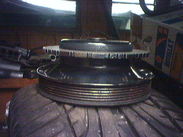
???, That would be awesome. I was thinking to mount the trigger wheel in-between the harmonic damper (balancer) and the serpentine belt pulley. Three holes or circular slots would have to be machined into the trigger wheel to match the holes on the pulley. Then use the corvette pulley (which has a smaller offset then the f-body pulley) and have a spacer machined to push the corvette pulley out to match the F-body offset.
Another option, which would not require changing the trigger wheel used in the above example would be to mount it behind the damper with a LT1 crank damper hub and a LT1 damper. Anyone know if a LT1 damper setup can be used on a gen1 SBC? Are the engines balanced differently?
???, how and where are you mounting the trigger wheel?
To better explain what I said above about slots. The black slots in the image below would be cut out slots where the bolt would go through the pulley and squeeze the trigger wheel between the pulley and the damper. This is just a rough drawing, it would make more sense to use three slots instead of four since the pulley only has three bolts.
The other option is to just do a ring of bolt holes, which would be easier but not allow you to dial in an exact angle for the trigger wheel.
Last edited by 89 Iroc Z; 08-19-2009 at 10:33 PM.
08-20-2009, 08:08 AM
#188
Senior Member
Re: Do away with dizzy?
couldn't hurt to have a look if you have a scanner and wouldn't mind. the more info online the better for guys trying this. I have a buddy working on lazer cutting 3 wheels out for me now. so I'm not giving up on this for a while. I want my 3rd gen to run on this as well as his 4th gen.
08-20-2009, 08:13 AM
#189
TGO Supporter
Join Date: Aug 2001
Location: NJ/PA
Posts: 1,008
Likes: 0
Received 0 Likes
on
0 Posts
Car: Yes
Engine: Many
Transmission: Quite a few
Re: Do away with dizzy?
the lt1 damper is the lower pulley, which is no big deal, but the hub is not machined for a keyway, so you'd need to just use the bolt. I think the balance it close, but closer to a 305 bobweight due to the lighter components from the factory. The hub and balancer also don't have a symmetrical bolt pattern, one of the bolts is slightly off center, took me a bit to figure out what was going on.....
if you use a normal balancer and use the right thickness plate for the reluctor, I think you could bolt it onto the back of the balancer using the three tapped holes for the puller, and make the bolts long enough that the pulley would get mounted with nuts and washers from the front, so you'd have like studs protruding from the balancer.
I would get the reluctor on the balancer as exactly as possible, then make fine adjustments on the sensor bracket.
08-20-2009, 10:47 AM
#190
Re: Do away with dizzy?
???, That would be awesome. I was thinking to mount the trigger wheel in-between the harmonic damper (balancer) and the serpentine belt pulley. Three holes or circular slots would have to be machined into the trigger wheel to match the holes on the pulley. Then use the corvette pulley (which has a smaller offset then the f-body pulley) and have a spacer machined to push the corvette pulley out to match the F-body offset.
Another option, which would not require changing the trigger wheel used in the above example would be to mount it behind the damper with a LT1 crank damper hub and a LT1 damper. Anyone know if a LT1 damper setup can be used on a gen1 SBC? Are the engines balanced differently?
???, how and where are you mounting the trigger wheel?
To better explain what I said above about slots. The black slots in the image below would be cut out slots where the bolt would go through the pulley and squeeze the trigger wheel between the pulley and the damper. This is just a rough drawing, it would make more sense to use three slots instead of four since the pulley only has three bolts.
The other option is to just do a ring of bolt holes, which would be easier but not allow you to dial in an exact angle for the trigger wheel.
Another option, which would not require changing the trigger wheel used in the above example would be to mount it behind the damper with a LT1 crank damper hub and a LT1 damper. Anyone know if a LT1 damper setup can be used on a gen1 SBC? Are the engines balanced differently?
???, how and where are you mounting the trigger wheel?
To better explain what I said above about slots. The black slots in the image below would be cut out slots where the bolt would go through the pulley and squeeze the trigger wheel between the pulley and the damper. This is just a rough drawing, it would make more sense to use three slots instead of four since the pulley only has three bolts.
The other option is to just do a ring of bolt holes, which would be easier but not allow you to dial in an exact angle for the trigger wheel.
08-31-2009, 12:53 AM
#191
Re: Do away with dizzy?
spend some time on this friday night(till 3am lol) and got no where again.
I'll post up a log and the bin its from incase anyone has time to double check what I've done. but for now, the A1 bin that is said to work as a good starter for a northstar running off a 730 didn't work, it had idle timing that was to high and when reved the timing went the wrong way and the timing light flashed unevenly and the motor wasn't happy at all, eaziest way to explain it is it sounded like a drag car sitting on a 2step at the light, but still reved up with more throttle (so not hitting a limiter), just the exhaust pops got worse. it sounded really bad for it, so we didn't do that long. we figured it was confusing cyl or something.
we tried the idea of connection the ref hi output, to the ecm input of the icm while applying 5v to the bypass wire and that didn't get anything. it was said to show the true ref angle built into the icm. it didn't for us.. we loaded up the 8D with the code changes above and got pretty much the same outcome as the A1 but with different timing values, but the same popping and timing all over the map.
I even loaded up a dead stock aujp bin without any timing changes. it idled at 0* timing when TP was displaying 27* then went to over 45* when reved up while TP said the ecm was trying to run 34*ish. with the same uneven timing light flickering anything above idle and exhaust popping. I saw no clipping or locking of timing, it changed but randomly and with no real rime or reason.. I even tried adding 27* to the whole coolant temp timing table and then got over 30* at idle and off the scale reved up and more bad running. we both found that weird, and leads up to believe we may have a hardware issue but the car runs and revs fine with the bypass wire pulled and with the sensors move up to get around 30* timing while bypassed, the car runs and drive just like you would expect a lt1 to, on a tpi tune, tip ae isn't right but it still runs, drives, starts and pulls thru the revs up to around 4500rpms where it lays down, which I expected from the tpi ve tables falling off up there.
going to fab up the new crank wheel whenever they get here, maybe lost in the mail lol. been over a week and haven't seen the box. but if all else failed, I thought forsure the A1 bin would have atleast controlled the timing right. we even tried the trick off page one of this thread about using the icm's tach output to the ecm ref hi and no change at all. I'm starting to loose faith we can pull this off. I'm starting to wonder if the 4x output isn't really a 6x output and causing all the popping.
here's the 8d bin and ads file session 1 session 2 is the A1, so i went ahead and uploaded that bin too.
09-02-2009, 10:00 AM
#193
Re: Do away with dizzy?
Corner Worker or anyone who is getting trigger wheels cut using my CAD file do you mind making an extra and shipping it to me for a cheap price or at cost. For the work I did on the CAD design, etc.
I have the original trigger wheel cut out of a N* crank which I used to make the CAD file but it would have to be milled flat on both sides to mount and I no longer have access to a machine shop.
- Luke
I have the original trigger wheel cut out of a N* crank which I used to make the CAD file but it would have to be milled flat on both sides to mount and I no longer have access to a machine shop.
- Luke
you have a pm
 09-02-2009, 12:39 PM
#195
TGO Supporter
Join Date: Aug 2001
Location: NJ/PA
Posts: 1,008
Likes: 0
Received 0 Likes
on
0 Posts
Car: Yes
Engine: Many
Transmission: Quite a few
Re: Do away with dizzy?
I dug up some old northstar stuff from when i prototyped this (never got any further), and I see I made up a spreadsheet with some reference angles listed. I can't remember how I did this, but I have the northstar reference angle to be measured on the bench at around 25 degrees, not 70 as has been referred to here. I might have looked at the delta between the first pulse listed as the first notch, compared to the first 4x ref pulse, and then verified it to be close to that with a dial back timing light. I went further and calculated what the min and max retard should be, so I came up with this:
ref angle: 25
max advance: 18
max retard: -28
I dunno if they will work or not, but it's what I had calculated here. Oh, the overall advance range with these values is -3 to 43 degrees.
ref angle: 25
max advance: 18
max retard: -28
I dunno if they will work or not, but it's what I had calculated here. Oh, the overall advance range with these values is -3 to 43 degrees.
Last edited by jwscab; 09-02-2009 at 12:43 PM. Reason: added more info.
09-04-2009, 08:54 PM
#196
Re: Do away with dizzy?
i will try those values for sure. he's working on mounting the new wheel and making sure the sensor's are in the right place. about a week or so i'd guess and we will know for sure if its working, or if we are scrapping the idea on his car since its been down for a few months now over this and go another way.
maybe something lsx based or off the wall.
maybe something lsx based or off the wall.
09-04-2009, 09:11 PM
#197
Re: Do away with dizzy?
i just tried emailing them about this and attached your scanned pic to it. hope i hear something
http://www.indmar.com/About/ContactIndmar/index.html
http://www.indmar.com/About/ContactIndmar/index.html
09-08-2009, 02:28 PM
#198
Re: Do away with dizzy?
afgun you are the man...
The sensor bracket is P/N S536051. The bracket sells for $167.00 The trigger wheel is P/N S536050 and it sells for $316.00 The crank sensors are P/N S556036 and they sell for $37.50 EACH We have all of these parts in stock. Larry Engelbert Indmar Service Power to the Sport
 09-08-2009, 03:14 PM
#200
Supreme Member
Join Date: Aug 2001
Location: Costal Alabama
Posts: 2,136
Likes: 0
Received 1 Like
on
1 Post
Car: 1989 Iroc-Z
Engine: 350, ZZ4 equivalent
Transmission: Pro-Built Road Race 700R4
Axle/Gears: 3.23 Dana 44
Re: Do away with dizzy?
afgun you are the man...
The sensor bracket is P/N S536051. The bracket sells for $167.00 The trigger wheel is P/N S536050 and it sells for $316.00 The crank sensors are P/N S556036 and they sell for $37.50 EACH We have all of these parts in stock. Larry Engelbert Indmar Service Power to the Sport
- Luke