

Coolant Flow ?


Thread Starter
Supreme Member

Joined: Jan 2002
Posts: 3,852
Likes: 1
From: Valley of the Sun
Car: 82 Z28
Engine: Al LT1 headed LG4 305
Transmission: TH350
Axle/Gears: 3.73 posi with spacer
Coolant Flow ?
Does anybody have a coolant flow diagram for an SBC. I'm am going to be swapping one some LT1 heads on my 305 and have heard that i only need to bore holes in the front of the heads to go into the intake and thermostat. I'm running a Weiand Stealth carb intake...
I'm trying to figure out if it would be easier to do this or just make a remote thermostate.
Can anybody help me, or have any suggestions?
I would really like to know how and where the coolant enters and exits the heads. What it the purpose to the crossover tube in the front intake manifold where the thermostat is? How does that system/setup work? Is that just the exit of the cooling system where the coolant goes to the radiator? Does coolant come from each head into the thermostat/exit/radiator inlet?
I'm just trying to figure out how the coolant flows. Is the system cirulatory, where the coolant enters one side of the block/heads and travels around to the other side?
Thanks

Member
Joined: Jan 2002
Posts: 266
Likes: 0
From: Morrison, Colorado
Car: 1986 IROC-Z
Engine: 355 ci TPI, 10:1 cr, Isky cam, ported heads, dual exhaust
Transmission: 700R4, ratchetting shifter, 3.23 rear
Wow. Converting a 305 to a reverse coolant flow LT1 head system? That's interesting. If I were you, I'd do it the same way GM did it on the LT1 motors. Which means you might get away with a Chilton or Haynes manual for an early 4th gen F-body that used the LT1 motor.
Member
Joined: Jan 2002
Posts: 266
Likes: 0
From: Morrison, Colorado
Car: 1986 IROC-Z
Engine: 355 ci TPI, 10:1 cr, Isky cam, ported heads, dual exhaust
Transmission: 700R4, ratchetting shifter, 3.23 rear
Come to think of it, 305's had tiny combustion chambers in their heads, didn't they? Something like 58cc's? I'm almost certain the LT1 heads have a significantly larger combustion chamber size, which will drastically hurt your 305's compression ratio. You need to research that further.

Supreme Member
Joined: Aug 2001
Posts: 1,770
Likes: 1
From: Pacific Northwest
Car: '85 IROC
Engine: LB9
Transmission: 700 R4
The coolant flows from the lower outlet on the radiator, to the water pump, exits the water pump to the block, from the block it flows through several holes into the heads, and from the heads it flows through the rectangular holes at the front of the head, to the thermostat, and back to the radiator through the top hose.
On those heads I guess you could actually tap a hole into the front of the haed and put a fitting in there that goes to a remote thermostat. But the thermostat is there on your intake already.
Or maybe you could tap the rear of the heads for a water outlet fitting and a cleaner look.
Might be an air pocket problem with the outlet at the rear tho.
On one of your other threads I posted a link to a thread where they went over that stuff. With some nice pics too.
Thread Starter
Supreme Member
Joined: Jan 2002
Posts: 3,852
Likes: 1
From: Valley of the Sun
Car: 82 Z28
Engine: Al LT1 headed LG4 305
Transmission: TH350
Axle/Gears: 3.73 posi with spacer
I'm converting reverse flow heads to standard GEN I flow.
Thanks Bert, thats exactly what i wanted to know, you really know your stuff. I was kinda thinking of tapping the front of the heads and running some an lines to the tapped fittings on each side of the rectanglular thermostat port on the intake. I don't know if i want to bore the hole in the head for the sleeve/pipe connecting the thermostate in the intake. The tube setup others have used just seems kinda hokie and wierd to me. I think it would be easier and less risky to do something like.
Thanks Bert, thats exactly what i wanted to know, you really know your stuff. I was kinda thinking of tapping the front of the heads and running some an lines to the tapped fittings on each side of the rectanglular thermostat port on the intake. I don't know if i want to bore the hole in the head for the sleeve/pipe connecting the thermostate in the intake. The tube setup others have used just seems kinda hokie and wierd to me. I think it would be easier and less risky to do something like.
Supreme Member
Joined: Aug 2001
Posts: 1,770
Likes: 1
From: Pacific Northwest
Car: '85 IROC
Engine: LB9
Transmission: 700 R4
Yeah, I thought of doing something like that myself.
The thermostat housing already exists right there where it's always been, and it seemed like some external tubes connecting the heads to that might be less likely to leak. Or at least if they did leak, the leak would be visible and not on the inside of your engine.
Of course the ends of the thermostat housing on the intake would need to be sealed.
On one of the other threads someone posted the idea of the cyl head outlet passages in the rear of the head, accompanied by a small tube at the front for bleeding air/steam that might be trapped at the upper end of the head.
I wouldn't say that I really know my stuff, cause there's a lot that I don't know. I have spent some long hours pondering this swap though.
But thanks anyhow, Leigh
Thread Starter
Supreme Member
Joined: Jan 2002
Posts: 3,852
Likes: 1
From: Valley of the Sun
Car: 82 Z28
Engine: Al LT1 headed LG4 305
Transmission: TH350
Axle/Gears: 3.73 posi with spacer
I'm thinking i might be able to JB weld or epoxy some sort of aluminum plug or some thing in the intake.
Do you think the lines coming from the heads to the intake would be big enough and carry enough coolant? I'm not sure what size the plugs are on the intake i'd say 5/8 or 3/4 npt?
Do you think the lines coming from the heads to the intake would be big enough and carry enough coolant? I'm not sure what size the plugs are on the intake i'd say 5/8 or 3/4 npt?
Trending Topics
Senior Member
Joined: Mar 2001
Posts: 849
Likes: 2
From: MA
Car: 93 GM300 platforms
Engine: LO3, LO5
Transmission: MD8 x2
There is a thread here on TGO (which you'll have to search for) that shows pix on exactly what was done to a set of Gen II aluminum LT1 heads for use on a Gen I sbc --- which is, I think, what you are aiming for.
It could also be done on iron LT1 heads but you would have to get the heads welded by someone who knows how to weld cast iron --- not impossible but it may be a lot easier/cheaper to just get the aluminum LT1 heads instead. Or just opt for the L31s (same as iron LT1 head, only using conventional cooling). HTH.
It could also be done on iron LT1 heads but you would have to get the heads welded by someone who knows how to weld cast iron --- not impossible but it may be a lot easier/cheaper to just get the aluminum LT1 heads instead. Or just opt for the L31s (same as iron LT1 head, only using conventional cooling). HTH.
Thread Starter
Supreme Member
Joined: Jan 2002
Posts: 3,852
Likes: 1
From: Valley of the Sun
Car: 82 Z28
Engine: Al LT1 headed LG4 305
Transmission: TH350
Axle/Gears: 3.73 posi with spacer
I know about the article and what other people have done, but i'm trying to do it alittle differently. Tapping some lines in the heads instead of boring a hole and adding a tube for the thermostat housing.
Not like this
Not like this
Supreme Member
Joined: Aug 2001
Posts: 1,770
Likes: 1
From: Pacific Northwest
Car: '85 IROC
Engine: LB9
Transmission: 700 R4
I was thinking 5/8 min, 3/4 better.
An alum npt sleeve, JBwelded into the head would be good , I think. Then get some 90deg AN hose ends and some braided stainless hose to connect to the thermostat housing.
I was never aware if the iron L31 head that kdrolt suggested. Where can I find out more about those? Are those Vortecs?
An alum npt sleeve, JBwelded into the head would be good , I think. Then get some 90deg AN hose ends and some braided stainless hose to connect to the thermostat housing.
I was never aware if the iron L31 head that kdrolt suggested. Where can I find out more about those? Are those Vortecs?
Thread Starter
Supreme Member
Joined: Jan 2002
Posts: 3,852
Likes: 1
From: Valley of the Sun
Car: 82 Z28
Engine: Al LT1 headed LG4 305
Transmission: TH350
Axle/Gears: 3.73 posi with spacer
I'm thinking the same as you on those fittings. I'm liking this idea more and more now!
L31's are vortecs.
Oh yeah, heads should be here tomorrow, so i can actually look at them when i think! LOL
L31's are vortecs.
Oh yeah, heads should be here tomorrow, so i can actually look at them when i think! LOL
Thread Starter
Supreme Member
Joined: Jan 2002
Posts: 3,852
Likes: 1
From: Valley of the Sun
Car: 82 Z28
Engine: Al LT1 headed LG4 305
Transmission: TH350
Axle/Gears: 3.73 posi with spacer
I'm going to try and use my Weiand, its kinda like the stealth but was made before they called it that.
TGO Supporter
Joined: Jul 2003
Posts: 4,803
Likes: 2
From: Grand Rapids, MI
Car: Z28
Engine: Sb2.2 406
Transmission: Jerico 4 speed
Axle/Gears: Ford 9" 3.60
I'm guessing you have 1/2" NPT fittings up front then. Here's my thought:
Without seeing the heads exactly, drill and tap the front and rear water jackets int he head. Thread them all for -10 or 12 AN. That's 5/8" and 3/4" respectivly. For the rear's, run them directly to the 2 water ports on the head. You can get fittings that adapt 1/2" NPT to either 10 or 12 AN. For the front, run some -10 or -12 AN into a junction block and from the outside there, perhaps get some water neck or something like this:
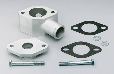
This is mere brainstorming, but you could see if you couldn't drill out the "bare" side for a -16 AN fitting. I'm sure somewhere out there there's a junction block that size (dual -12 AN inlet, single 16 AN outlet). If not, get creative. That or just plumb both directly to the spacer. Just make a plate and bolt it on with another gasket to retain the radiators pressure cap function, or put a pressure cap on and move the hose. Hell, run dual overflow tanks!
Crazy, I know...
Without seeing the heads exactly, drill and tap the front and rear water jackets int he head. Thread them all for -10 or 12 AN. That's 5/8" and 3/4" respectivly. For the rear's, run them directly to the 2 water ports on the head. You can get fittings that adapt 1/2" NPT to either 10 or 12 AN. For the front, run some -10 or -12 AN into a junction block and from the outside there, perhaps get some water neck or something like this:
This is mere brainstorming, but you could see if you couldn't drill out the "bare" side for a -16 AN fitting. I'm sure somewhere out there there's a junction block that size (dual -12 AN inlet, single 16 AN outlet). If not, get creative. That or just plumb both directly to the spacer. Just make a plate and bolt it on with another gasket to retain the radiators pressure cap function, or put a pressure cap on and move the hose. Hell, run dual overflow tanks!
Crazy, I know...
Thread Starter
Supreme Member
Joined: Jan 2002
Posts: 3,852
Likes: 1
From: Valley of the Sun
Car: 82 Z28
Engine: Al LT1 headed LG4 305
Transmission: TH350
Axle/Gears: 3.73 posi with spacer
So are you saying tap the rears of the heads and run a line between them.
I don't get why i need the junction block, isn't that just like the thermostat housing already in the intake?
I measured the thread diameter of the plugs that are in the intake. They measure 13/16" so i assume they are 3/4" NPT.
I don't get why i need the junction block, isn't that just like the thermostat housing already in the intake?
I measured the thread diameter of the plugs that are in the intake. They measure 13/16" so i assume they are 3/4" NPT.
TGO Supporter
Joined: Jul 2003
Posts: 4,803
Likes: 2
From: Grand Rapids, MI
Car: Z28
Engine: Sb2.2 406
Transmission: Jerico 4 speed
Axle/Gears: Ford 9" 3.60
The rears would go to whatever NPT the intake is. Try to match the AN line to the NPT, that's all. So now you are down to 1 threaded port on the intake, and that's for the water pump I presume. So you need somewhere to take the fronts.
Wait wait, skip my water neck thing. That's on the wrong side of the stat. Oops. Drill and tap the intake for another port then. The front lines have to go somewhere. Basically, try not to restrict flow from the heads to the intake too much.
Damn Leigh, you need a messenging service.
Wait wait, skip my water neck thing. That's on the wrong side of the stat. Oops. Drill and tap the intake for another port then. The front lines have to go somewhere. Basically, try not to restrict flow from the heads to the intake too much.
Damn Leigh, you need a messenging service.
Last edited by Stekman; Dec 22, 2004 at 10:05 PM.
Thread Starter
Supreme Member
Joined: Jan 2002
Posts: 3,852
Likes: 1
From: Valley of the Sun
Car: 82 Z28
Engine: Al LT1 headed LG4 305
Transmission: TH350
Axle/Gears: 3.73 posi with spacer
So you are saying that i need to run two lines, 2 from the fronts and 2 from the back?
I couldn't just have two on the front go to the thermostat housing? Would that be too restrictive?
This is what i'm really trying to figure out, how the coolant flows around the engine.
I couldn't just have two on the front go to the thermostat housing? Would that be too restrictive?
This is what i'm really trying to figure out, how the coolant flows around the engine.
Thread Starter
Supreme Member
Joined: Jan 2002
Posts: 3,852
Likes: 1
From: Valley of the Sun
Car: 82 Z28
Engine: Al LT1 headed LG4 305
Transmission: TH350
Axle/Gears: 3.73 posi with spacer
Originally posted by Stekman
Damn Leigh, you need a messenging service.
Damn Leigh, you need a messenging service.
Supreme Member
Joined: Aug 2001
Posts: 1,770
Likes: 1
From: Pacific Northwest
Car: '85 IROC
Engine: LB9
Transmission: 700 R4
Originally posted by ME Leigh
This is what i'm really trying to figure out, how the coolant flows around the engine.
This is what i'm really trying to figure out, how the coolant flows around the engine.
Thread Starter
Supreme Member
Joined: Jan 2002
Posts: 3,852
Likes: 1
From: Valley of the Sun
Car: 82 Z28
Engine: Al LT1 headed LG4 305
Transmission: TH350
Axle/Gears: 3.73 posi with spacer
I've finally got it all figured out i've been chatting with Mike (Stekman) for a couple of hours now. Boy was i way off base in my thinking. Coolant flow into the block from the pump shhshh, lol.
Thanks guys!
Thanks guys!
Last edited by ME Leigh; Dec 23, 2004 at 01:40 AM.
Supreme Member
Joined: Aug 2001
Posts: 1,770
Likes: 1
From: Pacific Northwest
Car: '85 IROC
Engine: LB9
Transmission: 700 R4
I hope that the way I described it is the way it goes.... From the radiator, to the pump, to the block, then to the heads, through the thermostat and back to the radiator. Right?
TGO Supporter
Joined: Jul 2003
Posts: 4,803
Likes: 2
From: Grand Rapids, MI
Car: Z28
Engine: Sb2.2 406
Transmission: Jerico 4 speed
Axle/Gears: Ford 9" 3.60
That's the general circle, yep. More or less if you include the heater core, but Leigh has gotten rid of that, so that need not apply.
Senior Member
Joined: Mar 2001
Posts: 849
Likes: 2
From: MA
Car: 93 GM300 platforms
Engine: LO3, LO5
Transmission: MD8 x2
As far as coolant transfer at the back of the heads, the Gen II L99/LT1/LT4 heads use a coolant transfer hard line that screws into each head. I don't know if it can be adapted to work on your application, but it would be great if it did.
Supreme Member
Joined: Aug 2001
Posts: 1,770
Likes: 1
From: Pacific Northwest
Car: '85 IROC
Engine: LB9
Transmission: 700 R4
Originally posted by ME Leigh
I measured the thread diameter of the plugs that are in the intake. They measure 13/16" so i assume they are 3/4" NPT.
I measured the thread diameter of the plugs that are in the intake. They measure 13/16" so i assume they are 3/4" NPT.
npt fittings are measures on the ID, so a 1/2"npt will be about 3/4" OD
TGO Supporter
Joined: Jul 2003
Posts: 4,803
Likes: 2
From: Grand Rapids, MI
Car: Z28
Engine: Sb2.2 406
Transmission: Jerico 4 speed
Axle/Gears: Ford 9" 3.60
Originally posted by Streetiron85
Those are actually 1/2" npt
npt fittings are measures on the ID, so a 1/2"npt will be about 3/4" OD
Those are actually 1/2" npt
npt fittings are measures on the ID, so a 1/2"npt will be about 3/4" OD

Thread Starter
Supreme Member
Joined: Jan 2002
Posts: 3,852
Likes: 1
From: Valley of the Sun
Car: 82 Z28
Engine: Al LT1 headed LG4 305
Transmission: TH350
Axle/Gears: 3.73 posi with spacer
I know i know AN-12 to 1/2 NPT it is. I'm still gonna try one first to make sure.
Thanks guys i'll post pics later today!!
Thanks guys i'll post pics later today!!
Thread Starter
Supreme Member
Joined: Jan 2002
Posts: 3,852
Likes: 1
From: Valley of the Sun
Car: 82 Z28
Engine: Al LT1 headed LG4 305
Transmission: TH350
Axle/Gears: 3.73 posi with spacer
Heres the long awaited head shots:
The tapped hole measures 1/2 od measured at the threads
The tapped hole measures 1/2 od measured at the threads
Last edited by ME Leigh; Dec 23, 2004 at 04:55 PM.
Supreme Member
Joined: Aug 2001
Posts: 1,770
Likes: 1
From: Pacific Northwest
Car: '85 IROC
Engine: LB9
Transmission: 700 R4
Killer!!
You're one lucky dude... For $157.
So the hole that goes into the cooling jacket looks like 3/8 npt, unless it's metric.
Is there a hole like that on both sides of both heads?
You're one lucky dude... For $157.
So the hole that goes into the cooling jacket looks like 3/8 npt, unless it's metric.
Is there a hole like that on both sides of both heads?
Thread Starter
Supreme Member
Joined: Jan 2002
Posts: 3,852
Likes: 1
From: Valley of the Sun
Car: 82 Z28
Engine: Al LT1 headed LG4 305
Transmission: TH350
Axle/Gears: 3.73 posi with spacer
Yes the id threads measure 7/16 and the od threads measure alittle more then 1/2
I'm looking for some labeled plugs right now, or running to the store.
I looked here http://www.engineeringtoolbox.com/16_750.html
and it looks like the holes in the ends are 1/4npt and the intake it infact 1/2 npt.
 guys
guys
I'm looking for some labeled plugs right now, or running to the store.
I looked here http://www.engineeringtoolbox.com/16_750.html
and it looks like the holes in the ends are 1/4npt and the intake it infact 1/2 npt.
guys Last edited by ME Leigh; Dec 23, 2004 at 04:56 PM.
Supreme Member
Joined: Aug 2001
Posts: 1,770
Likes: 1
From: Pacific Northwest
Car: '85 IROC
Engine: LB9
Transmission: 700 R4
The more I think about it the more I become convinced that the 305/Carbed LT1 retrofit is an idea that should have been thought of a long time ago.
The std LT1 heads are actually a bit small to be considered a true HP head for the 350 or 383, with 170cc ports and 1.94 valves. But for a 305 they fit into the HP slot perfectly!
An added plus is the price. And after the mods, when the 305 finally gets tired, you could probably sell the heads for what you have invested in them or maybe even a profit.
So you'll have this on the road by New Years... Right, Leigh?
Thread Starter
Supreme Member
Joined: Jan 2002
Posts: 3,852
Likes: 1
From: Valley of the Sun
Car: 82 Z28
Engine: Al LT1 headed LG4 305
Transmission: TH350
Axle/Gears: 3.73 posi with spacer
I know its such a great idea, toot toot!
Yeah new years it is!! I have to pull the engine, buy the cam, get the heads welded, milled, and i have to install everything. 7 days should be way more then enough especially when the machine shop isn't open.
Me and Mike (Stekman) are still working on the head cooling setup.


Yeah new years it is!! I have to pull the engine, buy the cam, get the heads welded, milled, and i have to install everything. 7 days should be way more then enough especially when the machine shop isn't open.
Me and Mike (Stekman) are still working on the head cooling setup.
Last edited by ME Leigh; Dec 23, 2004 at 07:34 PM.
Member
Joined: Jan 2002
Posts: 266
Likes: 0
From: Morrison, Colorado
Car: 1986 IROC-Z
Engine: 355 ci TPI, 10:1 cr, Isky cam, ported heads, dual exhaust
Transmission: 700R4, ratchetting shifter, 3.23 rear
Just out of curiosity, what is the benefit to converting a 305 to a carbed LT1 headed 305?
Thread Starter
Supreme Member
Joined: Jan 2002
Posts: 3,852
Likes: 1
From: Valley of the Sun
Car: 82 Z28
Engine: Al LT1 headed LG4 305
Transmission: TH350
Axle/Gears: 3.73 posi with spacer
I am doing it mainly for the cheap Al heads and its accompaning weight savings.
The ports are 170cc and flow 214@.400" and 215@.500" in totally stock form. They also come with screw in studs stock.
Another added benefit is that LT1 heads have a 53-53cc fastburn chamber.
Its not worth it for a lot of people, because there are alot of mods that need to be made for LT1 heads to work on GEN I applications. But i'm going to alot of the work myself, but it is still alot of work. There are cooling passages issues, bolt hole issues....
Supreme Member
Joined: Aug 2001
Posts: 1,770
Likes: 1
From: Pacific Northwest
Car: '85 IROC
Engine: LB9
Transmission: 700 R4
Will the block be decked?
.028" head gasket possibly?
I just looked at my CR calculator and a std bore 305 with .040" piston to head clearance and 53cc chamber yields about 10.4/1 CR.
.028" head gasket possibly?
I just looked at my CR calculator and a std bore 305 with .040" piston to head clearance and 53cc chamber yields about 10.4/1 CR.
TGO Supporter
Joined: Jul 2003
Posts: 4,803
Likes: 2
From: Grand Rapids, MI
Car: Z28
Engine: Sb2.2 406
Transmission: Jerico 4 speed
Axle/Gears: Ford 9" 3.60
All things equal, it's a ~5cc drop in total volume. I don't think that's enough to send a 9.5:1 to 10.4:1. Maybe 10-10.25.
I may be crazy, though.
Leigh, port 'em out.
I may be crazy, though.
Leigh, port 'em out.
Last edited by Stekman; Dec 24, 2004 at 02:09 PM.
Supreme Member
Joined: Aug 2001
Posts: 1,770
Likes: 1
From: Pacific Northwest
Car: '85 IROC
Engine: LB9
Transmission: 700 R4
Originally posted by Stekman
All things equal, it's a ~5cc drop in total volume. I don't think that's enough to send a 9.5:1 to 10.4:1. Maybe 10-10.25.
I may be crazy, though.
All things equal, it's a ~5cc drop in total volume. I don't think that's enough to send a 9.5:1 to 10.4:1. Maybe 10-10.25.
I may be crazy, though.
I recalculated with .065" piston to deck clearance, which is about typical for a non decked block, and the CR ended up at about 9.8/1.
Last edited by Streetiron85; Dec 24, 2004 at 06:31 PM.
Thread Starter
Supreme Member
Joined: Jan 2002
Posts: 3,852
Likes: 1
From: Valley of the Sun
Car: 82 Z28
Engine: Al LT1 headed LG4 305
Transmission: TH350
Axle/Gears: 3.73 posi with spacer
I'm going to cc and measure everything so i can come up with 10.2:1 or so with a little grinding, massaging as necessary.
Supposedly my motors a 83 LG4 from the suffix codes. I will know what i have when i pull the motor and rip the heads off.
Supposedly my motors a 83 LG4 from the suffix codes. I will know what i have when i pull the motor and rip the heads off.
TGO Supporter
Joined: Jul 2003
Posts: 4,803
Likes: 2
From: Grand Rapids, MI
Car: Z28
Engine: Sb2.2 406
Transmission: Jerico 4 speed
Axle/Gears: Ford 9" 3.60
Leigh, your info says LU5, which has about a full point over what the LG4 engines did. Makes a big difference. Which engine is the base platform for this?
Thread Starter
Supreme Member
Joined: Jan 2002
Posts: 3,852
Likes: 1
From: Valley of the Sun
Car: 82 Z28
Engine: Al LT1 headed LG4 305
Transmission: TH350
Axle/Gears: 3.73 posi with spacer
I know its some screwy screwy stuff. The car VIN under the windshield says its a 82 LU5. There is a badge in the interior that says crossfire injection. I have the function crossfire SFC hood.
Now the partial vin on the radiator support says its a 83 LG4. The engine suffix code says its a 83 LG4.
I'm thinking somebody did some devious fixing before i bought it 5 years ago. Or had a wrecked 82 and swapped crap over to the 83, but why switch the vin tag. Devious, devilsh, crazy kids!
I'm going to shoot for atleast 10:1. I have to get the heads milled anyway after welding them.
But i won't know for sure if the engine has flat-tops, if its been rebuilt, or even if its any good till i pull it in a couple of weeks, when it starts dumping snow. I don't have a heater, and we all know how much fun they are to drive in the snow. So when the snow flys the engine is coming out.

Supreme Member
iTrader: (1)
Joined: Jun 2003
Posts: 3,085
Likes: 2
From: Elgin, IL
Car: 1997 Corvette
Engine: LS1
Transmission: 4L60E
Axle/Gears: 2.73 IRS
Ah! I can't believe I haven't checked this part of the boards in a while. I've missed all of the discussion on my own topic! 
I'm going with the LT1 heads and intake and I'm using a remote t-stat housing, but I was trying to figure some coolant things out as well.
Was trying to decide which size fittings to tap the front of the heads for. I'm trying to figure out how I'm going to get room in the front of the heads though to figure out the hoses. I may need to buy some aftermarket accessory brackets and use a setup very very similar to IROCZZ3.
Anyways, I'm going to go with a coolant line from the front of each head to the remote t-stat.
Then for the back, on the LT1, there was a tube that connected the two heads but also lead to the radiator. Just connecting the two heads does nothing to purge steam/air, but running it up to the radiator allows the steam to move into the radiator and exit the system. At least, this is what I understood from a diagram I saw of an LT1 coolant system. I'll try to dig up the diagram for you.
Also, as mentioned the chamber size is 53-54cc's and the runners are 170cc. If I had some more precise measuring devices, I'd measure the port volumes now that I have done some moderate porting. As soon as I grind down the little aluminum pieces to get welded into the holes...I'm going to take them to my cousin so he can take them to his buddy that ports heads. He'll weld em up for me and look over my porting, and hopefully flow em too These heads respond VERY well in the upper lifts (.450"+) with minor porting.
What else do you have planned? I'm going to be installing the ported LT1 heads (LT4 valvesprings), LT1 intake, 24# injectors, 210/220 cam + lifters, and headers at the same time I may install a ministarter too. Then I'll have to install my new Walbro 255lph and tubular LCAs, which has been sitting here for months. Then the 3-series Z-T posi carrier with 3.42 gears (also here) will be installed, and THEN it'll be time for either a manual swap or a higher stall torque converter. And then it'll be to the track for times with the 17" 10-spokes and 275/40r17 Nitto NT555Rs
I'm going with the LT1 heads and intake and I'm using a remote t-stat housing, but I was trying to figure some coolant things out as well.
Was trying to decide which size fittings to tap the front of the heads for. I'm trying to figure out how I'm going to get room in the front of the heads though to figure out the hoses. I may need to buy some aftermarket accessory brackets and use a setup very very similar to IROCZZ3.
Anyways, I'm going to go with a coolant line from the front of each head to the remote t-stat.
Then for the back, on the LT1, there was a tube that connected the two heads but also lead to the radiator. Just connecting the two heads does nothing to purge steam/air, but running it up to the radiator allows the steam to move into the radiator and exit the system. At least, this is what I understood from a diagram I saw of an LT1 coolant system. I'll try to dig up the diagram for you.
Also, as mentioned the chamber size is 53-54cc's and the runners are 170cc. If I had some more precise measuring devices, I'd measure the port volumes now that I have done some moderate porting. As soon as I grind down the little aluminum pieces to get welded into the holes...I'm going to take them to my cousin so he can take them to his buddy that ports heads. He'll weld em up for me and look over my porting, and hopefully flow em too
These heads respond VERY well in the upper lifts (.450"+) with minor porting.What else do you have planned? I'm going to be installing the ported LT1 heads (LT4 valvesprings), LT1 intake, 24# injectors, 210/220 cam + lifters, and headers at the same time
I may install a ministarter too. Then I'll have to install my new Walbro 255lph and tubular LCAs, which has been sitting here for months. Then the 3-series Z-T posi carrier with 3.42 gears (also here) will be installed, and THEN it'll be time for either a manual swap or a higher stall torque converter. And then it'll be to the track for times with the 17" 10-spokes and 275/40r17 Nitto NT555Rs