When you click on links to various merchants on this site and make a purchase, this can result in this site earning a commission. Affiliate programs and affiliations include, but are not limited to, the eBay Partner Network.
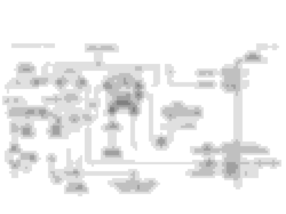
Im trying to get my car running after a carb swap. Im working with the following diagram:
Fuel pump ran fine a few weeks ago before i cut the ECM out of the loop. I decided to use the stock wiring as much as possible to keep things tidy, so I've got ignition power going to the green/white (+ in) to the relay, and the black/wht wire is going to engine ground. I tested that circuit and it's functioning just fine, and that's all I intended to mess with. Relay is switching properly when switched ignition power is applied to it.
But since I am blowing fuel pump fuses, I've crossed up something. Here is where I am confused. In my harness there is an orange wire coming in from the fuse holder that shows 12v from the battery at all times. This goes to pin A. Then there is a gray wire on pin E that shows a short to ground that appears to loop back to the C100 connector.
A - infinite resistance to ground, zero resistance to fuse holder
B - Ground for switching side of relay, working fine.
C - 12v for positive side of relay, working fine.
D - Test port
E - Short to ground, seems to go to C100 connector in firewall, no continuity to battery
Is it possible GM wired this backwards in reference to the above diagram due to year to year variation? Does anyone know where the wires are actually physically going? I think I am brainfarting on this, but it seems like pin E should go to the battery, and pin A should go to the fuel pump. But if somethign is grounding between the relay and the fuel pump itself, I dont know how I could have caused that. Am I missing something obvious here? If pin E does go to the fuel pump, would that show very low resistance to ground even if there wasnt a short since it is going through the fuel pump windings?
Edit:
Definitely looks like my wiring matches this diagram: