When you click on links to various merchants on this site and make a purchase, this can result in this site earning a commission. Affiliate programs and affiliations include, but are not limited to, the eBay Partner Network.
Engine SwapEverything about swapping an engine into your Third Gen.....be it V6, V8, LTX/LSX, crate engine, etc. Pictures, questions, answers, and work logs.
One is a universal sump which would use a mech pump to pump into sump.
Can't say I've heard of that arrangement.
Originally Posted by Hammer's Bird
The next is a new in line electric pump, with a pressure reg and return line.
This is my current set-up, still untested at this point but I know what to expect. It's a simple Holley Blue pump mounted where the original EFI fuel filter was (just forward of the driver's side wheel house) with a regulator on the front frame rail near the front of the engine using the factory supply and return lines although I did bring them across from the driver's side to the passenger side. My modest power output seems to be happy with the 3/8" inlet and 5/16" return. With this latest engine configuration (also un-tested), I may find that a 1/2" is needed for the supply and the return goes to 3/8ths.
Originally Posted by Hammer's Bird
The last is an in tank pump with a return as well as a baffet to prevent vapor lock and slosh issues.
If I were to do it all over again, I'd go that route. I've had excellent results with Aeromotive's Phantom series of in-tank pumps. Plenty of benefits, not the least of which is that this unit is quiet. Not like the Holly Blue (in-line) that is a pain in the ear. The Phantom is on the expensive side though.
Another option is to get an EFI tank from a junkyard (or the classifieds on TGO). Pull the pump/pickup and install a Walbro 255 & new pickup sock. You'll have to do some rewiring, but you'll have to do that with any electric pump option. You'll also have to remove any rubber in your current fuel line (should only be back at the pump until you get up into the engine compartment). I ran all new aluminum 3/8" line up to the engine.
I put an EFI pickup in my non-electric in-tank factory tank - no baffles, but that hasn't made that big of a difference for me. Baffles would be better, of course. I put a filter in the factory EFI location.
Funny you should ask. I was planning on posting an update today. We had a pretty good detour. Some time ago we had added a shift kit and rebuilt the 700R4 transmission. It broke and we finally got around to tackling that. Turned out the only part we didn't rebuild was the one that failed. The pump. So we opened it up and upgraded the pump and some of the other internals. That's working well. (and probably worth a post on the trans forum).
So now we're back to work on the 350.
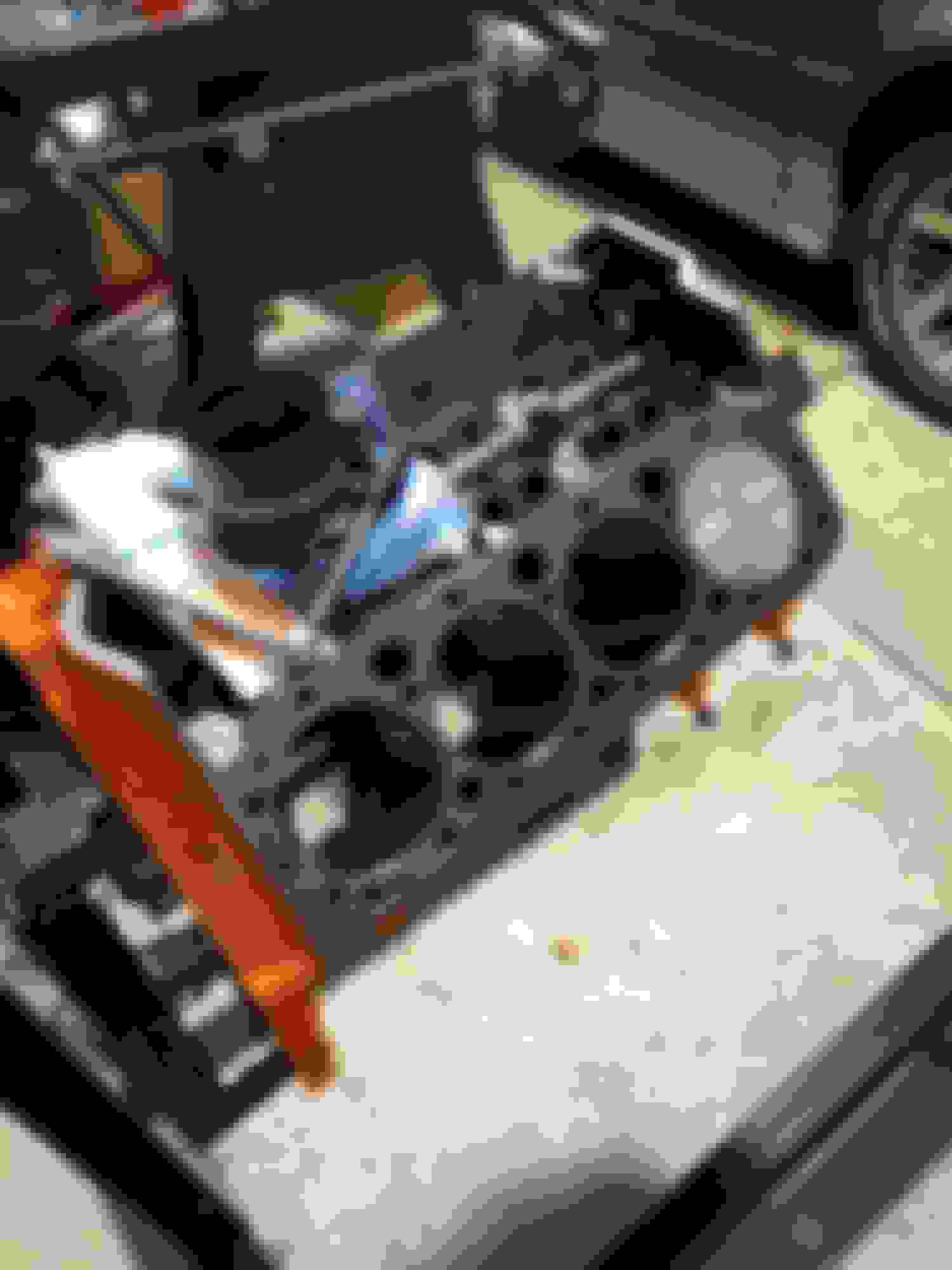
Didn't like the empty spot where fuel pump used to be.
So I got a cover, I know you don't see it much but I like it.
Got the pickup set into the new oil pump. They make a special tool for inserting the tube into the pump but I thought it was silly to spend that much for something I may not do again anytime soon. An open end wrench and a hammer and two people being careful got the job done.
ARP main bolts. New Melling oil pump and pickup.
New timing chain set.
Next up we wanted to degree the cam. That didn't seem to work at all. We tried measuring at .006, that was just silly. So then we tried the intake centerline method. We couldn't come up with numbers that made sense. So we pulled the cam to double check the numbers. They matched what we ordered. Put it back together and tried again. Same problems. We are working with the heads off. So this is the set up we used for the dial indicator.
Called Comp Cams tech line for advice. The suggested pulling the cam to check numbers. Ha, did that! Said they were correct. They suggested we could send the cam back and they would check the profile. I said we'd hold off on that. We decided it was unlikely the cam was wrong and our method must be wrong. But they reviewed what we were doing and said we were doing it correctly. So we thought we'd proceed with assembly and check again when the head were on. But as we moved on we noticed that the cam moved slightly. The bolts were not torqued. We torqued the bolts and rechecked. Now we're only 1.5 degrees off. Some sources say that 2 to 6 degrees of error is common. So we think its OK. We will recheck when the heads are on.
Regarding your margin of error with degreeing the cam. I've found that greater accuracy results from registering the dial indicator plunger in in the lifter cup rather that on the edge. Seems I was getting some slight hesitations on my dial readings as the tip was "teetering" on the edge of the lifter and skewing my results.
Looking good so far.
Care to refresh my memory regarding your compression ratios (SCR/DCR and cam selection)?
Thanks for the reply Skinny. We'll have to try the dial indicator in the cup and see if that helps.
The cam is a Comp Cams XR276HR-10.
Our original guesstimate on SCR was 10.157 and DCR 8.16.
I'm just a bit surprised when I checked two pistons for piston to deck height I came up with .041 and .035. I was thinking those numbers would be a bit smaller. More like. .025.
Those values aren't unusual with an undecked factory block. I had a new 1979 vintage 350 block that had piston decks that varied from .026 to .035. That was with resized rods and Speed Pro hypereutectic replacement pistons. Stock crank.
How you measure makes a big difference too as you can imagine. I used my dial to verify top dead centre and a bridge micrometer to confirm the straightedge/feeler gauge method.
Unfortunately, the effects of too much piston to head clearance are reduced combustion efficiency and reduction in detonation resistance due to the lack of mixture motion. The Vortecs have a very active chamber though and I found that even with cranking pressures approaching 200 psi and piston to head values of .060"+ (.036" deck (max) plus .026" gasket) , I was able to survive on premium fuel.
I wanted to understand the cam degreeing process better so I reran the process. I changed the setup for the dial indicator. Based on SkinnyZ's advice I set it up in the cup of the lifter. I also put in two lifters and set the dog bone on them. I was thinking that maybe the lifter was turning some and affecting the readings.
Through the wonders of modern technology, I made a Face Time call to my son in Florida. With him looking over my shoulder we went through the process again. He did the heavy thinking while I did the grunt work.
Dial indicator set in the cup of the lifter and dog bone spanning both lifters.
With the revised setup I felt I would get a better reading. The rig seemed stable and after double checking for TDC I ran the process again using the .006 lift.
The cam card said we should get .006 open at 32 BTDC. I measured 30.
The card called for close .006 at 64 ABDC. I measured 63.
I think those are pretty good numbers and I'm feeling we're in pretty good shape now.
I prefer the intake centre line method for dialing in a cam but whatever works. I think it's in Comps instructions where they say to measure .100" before and after max lift. My degree wheel is divided into quarters so the math is all over the place. I find the results to be very repeatable though.
As for the .015" head gasket, there are a number of caveats the first of which is whether the block is in good enough condition to accept one. There is a certain surface roughness value that must be met. It also must true (flat). I imagine the same applies to the heads although if they're new, then one can assume they will be suitable.
I've no direct experience with the shim gaskets. I've always relied on the Victor Reinz 5746 head gasket .026" x 4.125".
While the slight bump in compression is hardly worth chasing (by using a .015" gasket), the improved quench would be. The magic number that's thrown around is .040". This promotes a lot of mixture motion and reduces the chances of the end gases igniting on their own. It might be worth a shout out in another thread. There are a lot of forum members that use them.
I'm just a bit surprised when I checked two pistons for piston to deck height I came up with .041 and .035. I was thinking those numbers would be a bit smaller. More like. .025.
Frankly I'm surprised the numbers are that low.
Stock, the deck clearance is usually .025" +.010" or so, -.000". Then those pistons are designed to add .020" to that (their pin height is 1.54" instead of the stock 1.56"). Block evidently has been decked a bit, maybe .010" or so, somewhere along the line. Which makes sense because the numbers stamped in the pad aren't a factory code.
Frankly I wouldn't mess with the shim-stock gaskets. Your static CR is going to come out at around 9.3 (4.000" bore, 3.48" stroke, .040" deck clearance, .039" gasket, 64cc chambers, 6cc valve reliefs) , which isn't high enough to make chasing after quench necessary. You have more to lose in the near-certain short lifetime, especially on an unprepped deck as that one is, than you have to gain in quench. Use a composition gasket.
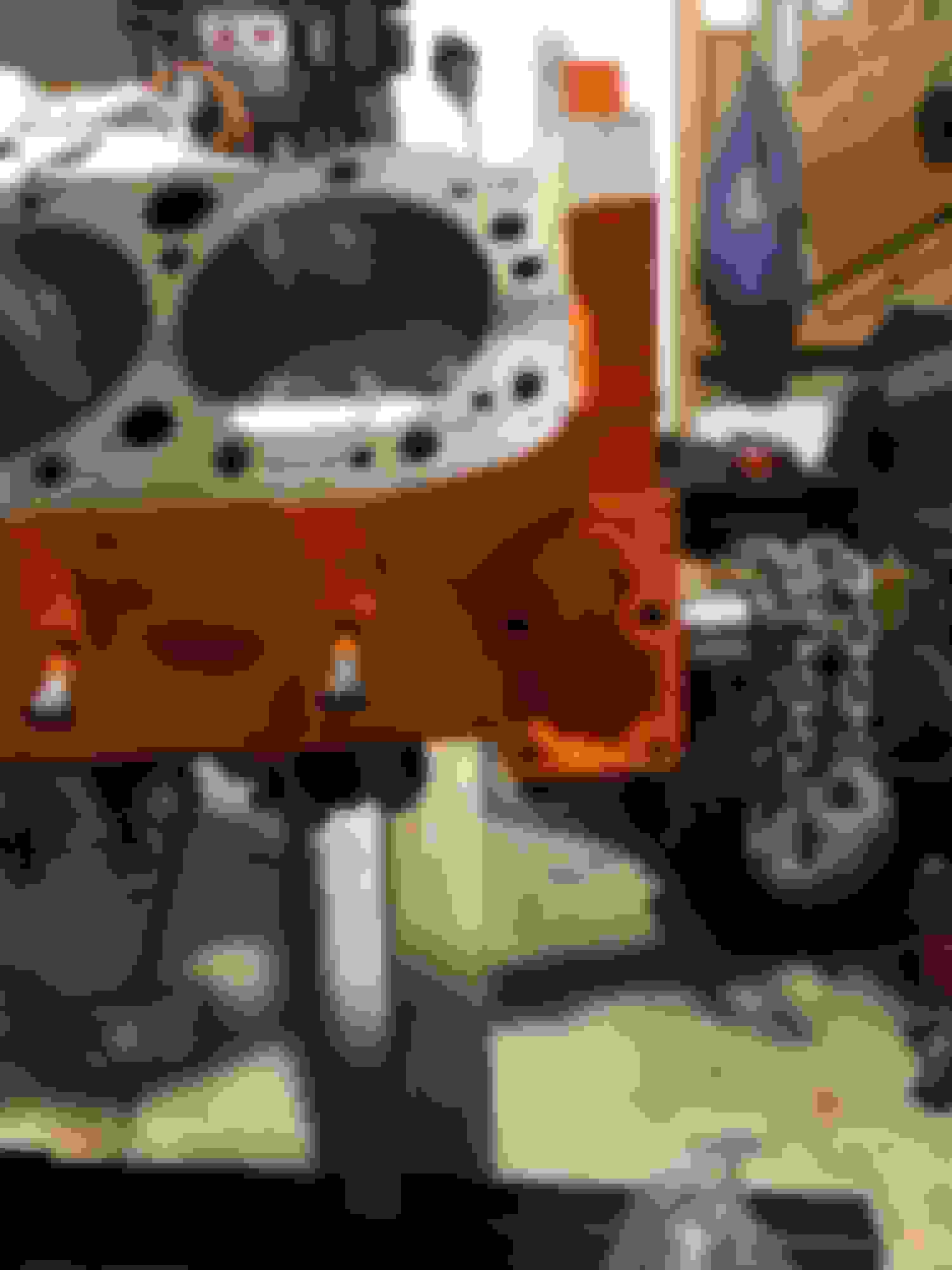
In fact you can see why that block came out of the car it used to be in: the head gasket blew between #2 & #4. The block is carrying around the obvious signs of the failure. Don't tempt the same fate on your new motor.
Be careful how you torque the head bolts. Overtorquing is the single most common cause of gasket failure. Use thread sealer with Teflon on the threads and under the bolt heads; use a beam or dial type torque wrench, NOT NOT NOT a "clicker"; Torque ONLY up to the low end of the spec (i.e. 60, NOT 65); torque them in steps, like 30, then 50, then 60 WITH THE BOLT MOVING (i.e. "turning" torque, NOT "breakaway" torque, which is why you DO NOT want to use a clicker); once you reach 60, go over them all at least once more in sequence until they are all at 60 WITH THE BOLT MOVING.
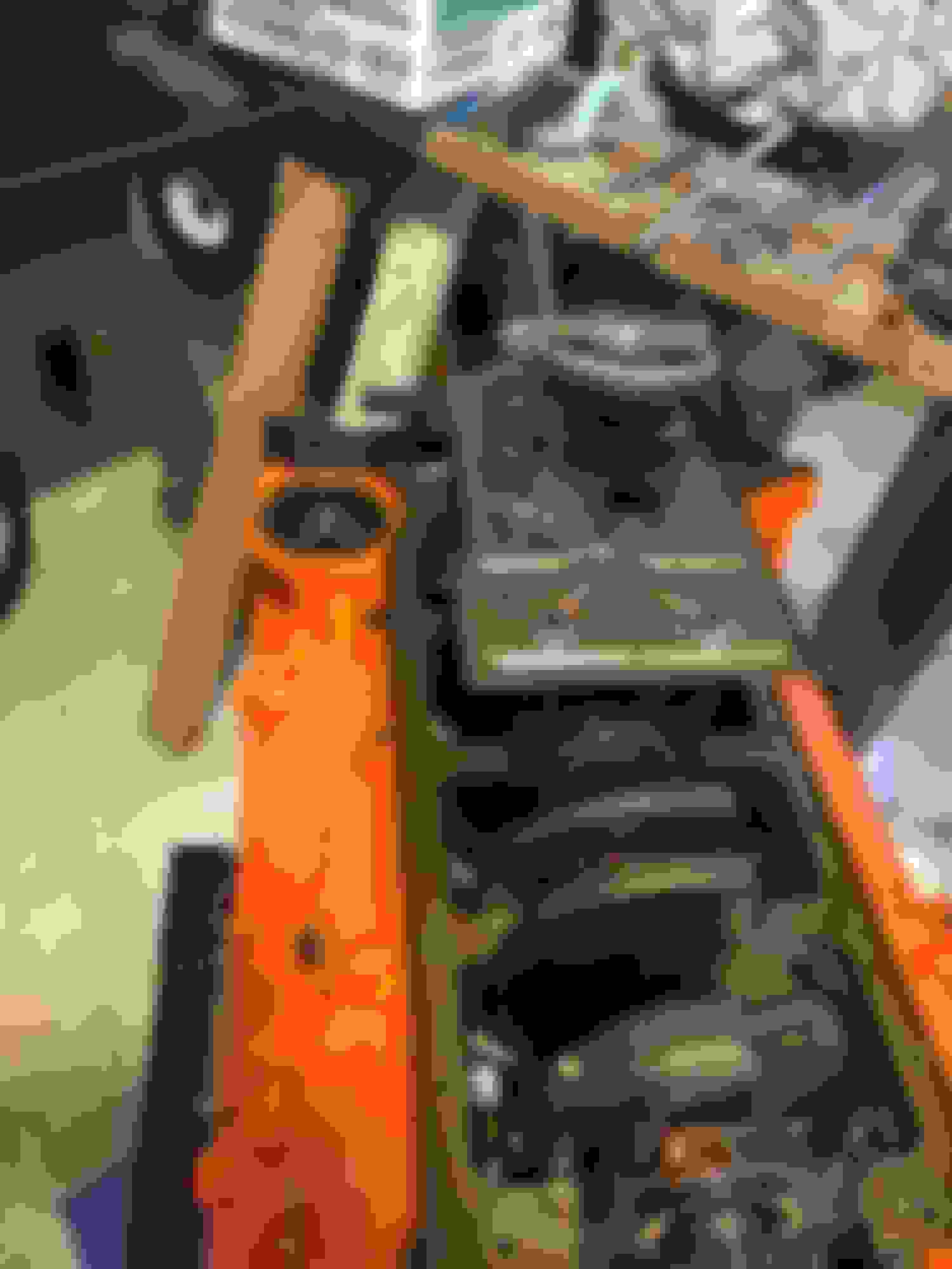
If that chain is a "truck roller", the cheeeeeeep "roller" type that's not actually a roller but rather has bushings instead of rollers, your cam timing will retard at least 10� from wherever you think it is now, within the first 1000 miles or so, making the whole "degree" process an exercise in futility. "Measure with micrometer, mark with chalk, cut with axe". If it's a REAL roller then it'll only retard a few degrees from break-in; maybe 2 - 3. IIRC Cloyes' words for that is "heavy duty" vs "true roller". Can't tell looking at the photos which chain it is.
I'd also recommend cleaning up all those burrs (grind or file) around the edge of the block decks before putting the heads on. That shoulda been done long ago in the cleanup process.
I'm not totally sure of the facts here, but this is my best impression from what we've seen so far. The engine appears to be a GM crate motor that was put into the vehicle not too long before it found it's way to the JY. There was no sign when we disassembled it of the head gasket being blown. It may be shadows or something you're seeing. There was no coolant in the oil or any other signs of engine failure. The vehicle appeared to be in the JY from accident damage in the rear. I cannot prove my theory but it makes sense. The car had stickers indicating it was a GM crate motor and the paint on the block was not in such condition to indicate the engine was as old as the vehicle.
Are crate motors made from new blocks or are they remanufactured? if remaned would that indicate the block having been decked before?
We will be cleaning up the block surface before the heads go on. What is showing there is a bit of sloppy painting on my part.
We will be using ARP head studs not bolts.
We are going to try to carefully measure each piston and see what pattern we have for how deep the pistons are in the holes.
I'll post more when we know more. Today was devoted to fixing the wife's vehicle. Happy wife, happy life.
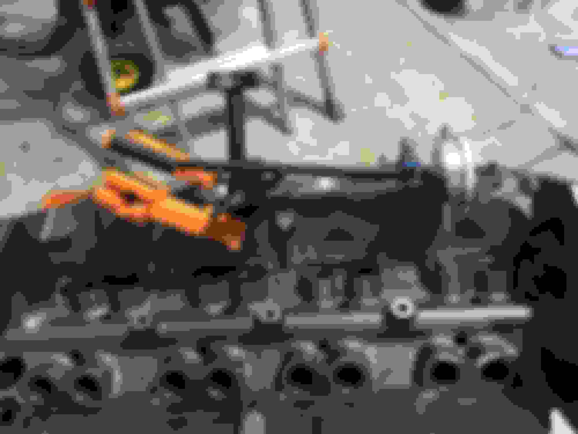
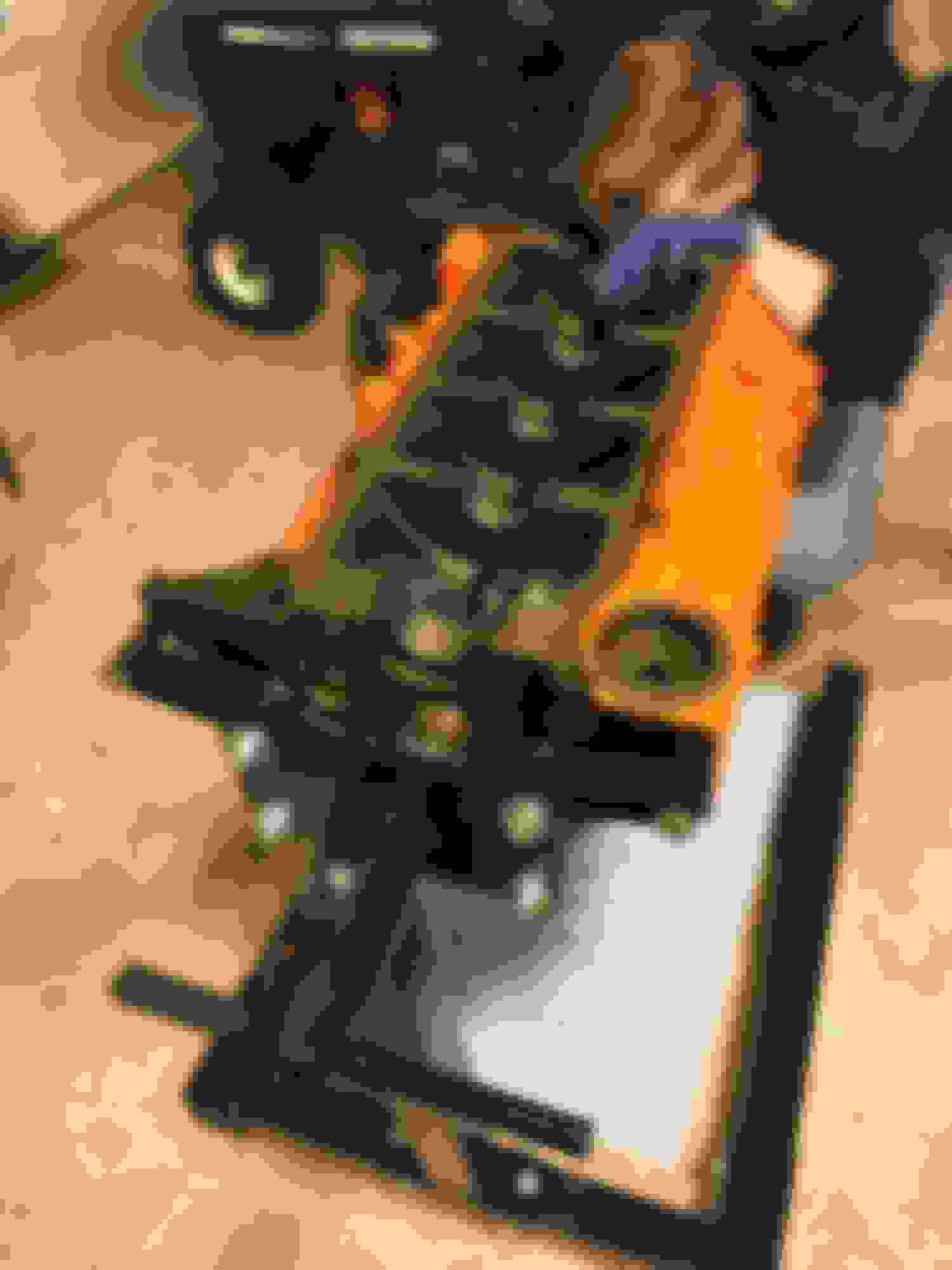
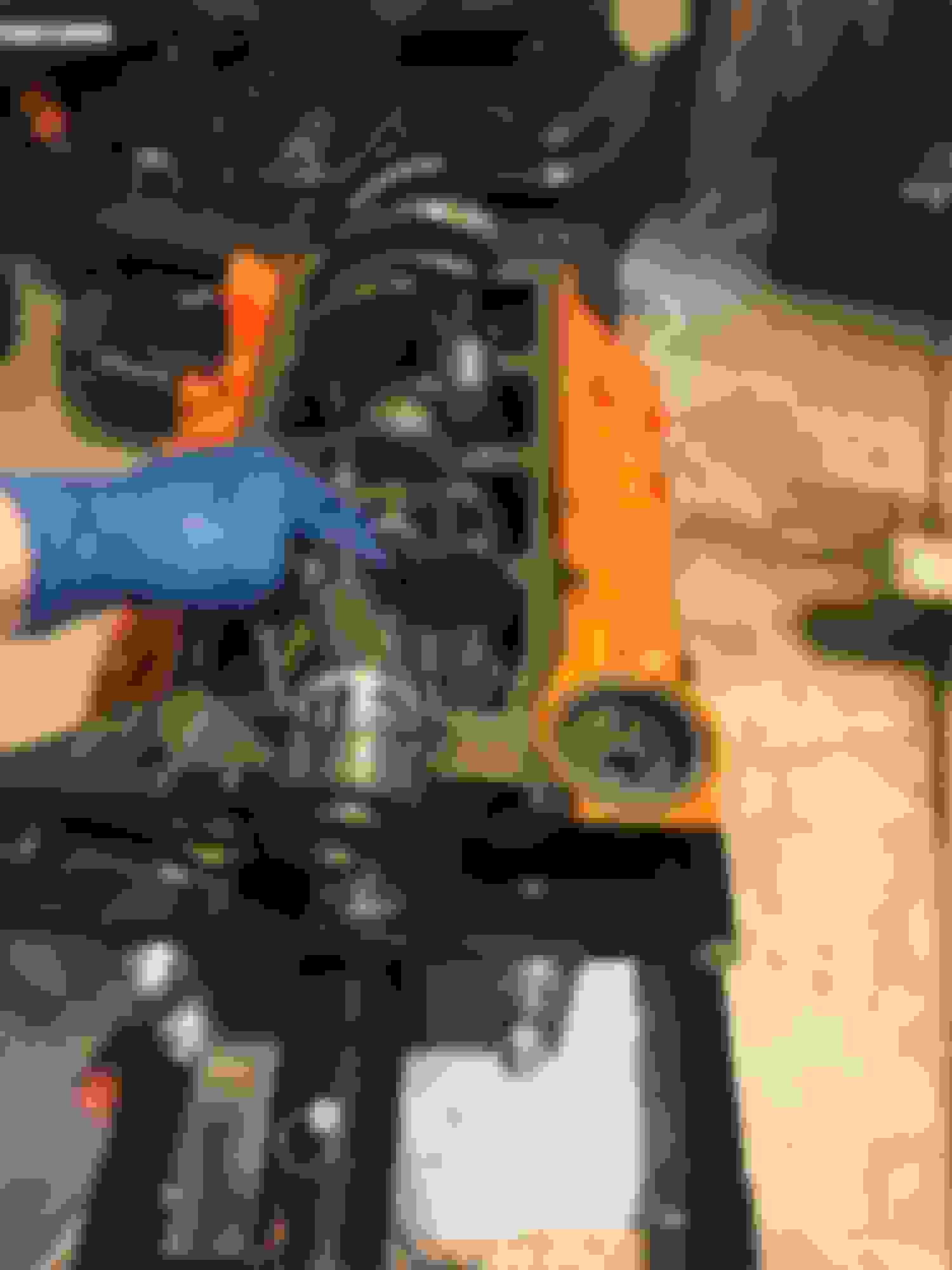
Had a machinist friend bring this over to measure how far the pistons are down in the bore. Not thrilled with the answers.<br/>
Here are the results
#1 .046 #2 .042
#3 .044.5 #4 .042
#5 .043 #6 .0415
#7 .040 #8 .042
So it appears the driver side has a slope to it. And both sides have the pistons deeper than we'd like.
The pistons are Speed Pro H345 DCP STD as I understand it their pin height is 1.548 versus the stock 1.560.
So is our best course of action to take it back apart and have the block decked?
Is there a limit on decking that we shouldn't go beyond? What number makes sense? Are there other effects down the line that result from decking that we need to be aware of?
Regardless of the pin height of the piston (at this point anyway) if you're finding the piston to deck value of "x" using a bridge micrometer ( and are certain of TDC) then that's what you deal with.
First off I'll say that thousands of SBCs have been built with less that optimum quench values. There's a compromise to doing that but you have to ask yourself, is it something that's going be to be cost effective to rectify vs the performance improvement?
That said, if .040" (nominal) is a piston to deck target then taking .026" + off the deck is needed. My understanding is that will approach the point where intake manifold fitment may become an issue. That number applied to the cylinder head work I recently had done and it appears I've dodged the bullet in that regard as .026" was milled from the heads and so far (after 350 miles and lots of 6500 RPM shifts) I've experienced no leaks externally.
I still may have internal leakage but haven't put on enough miles to observe any oil consumption.
One option you could consider is to use a .015" gasket. Since the deck is being cut, your machinist can ensure that the proper surface roughness is applied. To use the shim gasket and to guarantee proper sealing, you would need to make a clean up pass on the heads as well. At least with the .015"gasket, that's .011" less than what would be needed compared to a .026" composite gasket. The head pass, provided they are straight, shouldn't need to be more than a couple of thousandths.
Just a thought if you intend to proceed with changing your deck height.
Using the micrometer I checked the piston 2 degrees before what I believed was TDC, 1 degree before, at TDC, and 1 degree after. Based on that I adjusted the degree wheel about 1 degree. Then I checked each pair of cylinders 2 deg and 1 deg before, at TDC, and 1 degree after. I found TDC in each pair of pistons at 0 90 180 and 270. The measuring was done by an experienced machinist. I'm pretty confident in the numbers.
I stopped in at the speed shop. I showed them my numbers. They felt we could cut .030 off the deck. They did not feel that would interfere with intake manifold fit.
My compression height on the pistons is 1.548. To change pistons to ones with 1.560 would be about $250. They didn't show Speed Pros (we are using H345DCPSTD) with 1.560. So changing pistons did not seem viable, and it would only get us part way. We would still need to deck. Just less.
He didn't recommend the .015 gasket for a street engine. He recommended we not go below .026.
I have a .014" deck on my 355. Using a Victor Reinz/ Cometic/ Clevite 5746 graphite composite gasket got me to .040" piston to head clearance. Having done it, I can recommend it. Others have closed up the clearance to .035" but I think that's something to be cautious about.
The side that has the .006" spread may prove problematic and that's something to discuss with your machinist. I managed to get my block squared up but I also gave the entire reciprocating assembly to my machinist and let them have at it.
If its your block that's not parallel to the crank, then decking should remedy that. If the stack up of machining tolerances between the crank, rods and pistons has conspired against you to yield the .006" disparity, you and your machinist will have to come up with a plan. Either that or go with slightly different decks on one bank. My money is on the deck not being parallel to the crankshaft.
That would mean .028" off the right side and .032" tapered to .026" off the left.
You sound like you want to achieve a better quench value so that's why I'm suggesting what I am.
FWIW on any engine i'm building, i always have it decked, align bore/hone, magnaflux or sonic tested and fully balanced from pulley to flywheel or flexplate.
Just saved small headaches like what OP is dealing with right now.
FWIW on any engine i'm building, i always have it decked, align bore/hone, magnaflux or sonic tested and fully balanced from pulley to flywheel or flexplate.
Just saved small headaches like what OP is dealing with right now.
FYI, its "A line hone/bore", not align hone/bore.. Like, "My machinist uses a line bore/hone machine to do my cam tunnel".
FWIW on any engine i'm building, i always have it decked, align bore/hone, magnaflux or sonic tested and fully balanced from pulley to flywheel or flexplate.
Just saved small headaches like what OP is dealing with right now.
Exactly.
The previous block I worked with was a "new in box" 1979 original with zero miles. The decks ranged from .026" to .036". Whether that's a stack up of the crank, resized rods, new pistons and the casting and how much each contributed to the differences was never determined. If I had had the block squared up, the tune could have been dialed in more precisely. As it was, with the higher compression/short cam/ iron head combination, it often sounded one or two cylinders were in detonation. It easy to see how a change in SCR/DCR of 9.8/7.98 to 10.1/8.2 would contribute to that. The piston to head clearance was never any better than .051" with the biggest gap being .061". With a decked block, that gap could have been in the .040" range and that would have provided a greater degree of detonation resistance.
While that particular engine ran very well and went tens of thousands of miles, I always felt there was something left.
Here's hoping my new combination, with a decked block and an even .040" PTH value, will be more rattle resistant even though the SCR with the iron heads is now better than 10.2:1.
We are going to take it apart and head back to the machine shop to have the block decked.
But that will have to wait a bit. I'm out in Utah with my lovely wife touring the Mighty 5 National Parks. And my son is busy learning how to fly for the Marines so it will have to wait til I return in late October. Thanks for keeping us in mind. We are anxious to get going again.
Looks like a nice build, but at the risk of being a kill joy, that stock 700r4 is not going to last behind a 400 hp engine; be sure to put a transmission built to handle the additional power on the quick list of things to do. My stock tranny lasted three months behind a 430 HP 383 before busting the case, I bought a 700 Raptor transmission from PATC to replace it; hopefully it'll hold up.
An excellent point MSgt.
While my previous builds were less than 430 hp, I still made the more basic modifications to help the transmission along. Add to that, it was rebuilt by a local "expert" and so far, despite the heaps of abuse it gets (can you say tow a trailer with a disabled TCC for a few thousand miles in addition to being more than 50k old?), still stands up. Now the next test is my latest engine combination. This should tax it even further.
MSgt, agreed about a stock 700r4. We just finished a major upgrade of it. It had a shift kit but then the pump blew up. We went to a 13 vane pump, a Beast sunshell, upgraded to a 30 spline input shaft, etc. Long term my son wants to switch a stick but for now we think it will hold up to street use.
Well a long vacation with the wife and deer hunting are now over.
Took the engine back down to the bare block and dropped it off at the machine shop yesterday. They will deck the block and think it will be done next week.
Then we can reassemble. So now I have to start learning about how to determine pushrod length. I do have an adjustable pushrod to use.
There's more than one method for figuring out the valve train geometry. Several threads here too (some of which I've participated in).
If you want a little technical reading (and an interesting side story to rocker arm development) check this out. http://www.engineprofessional.com/do...2010_20-30.pdf
I use the mid-lift method as described in that paper.
Got the block back from the machine shop. Now it will need a thorough cleaning again before we start reassembly. I want to get it clean in the next week but I have to work around the arrival of a new grandchild. My son is coming home on leave for Christmas, so my plan is to get it ready to be reassembled on Dec 31 which will be the first day we can get time to work on it.
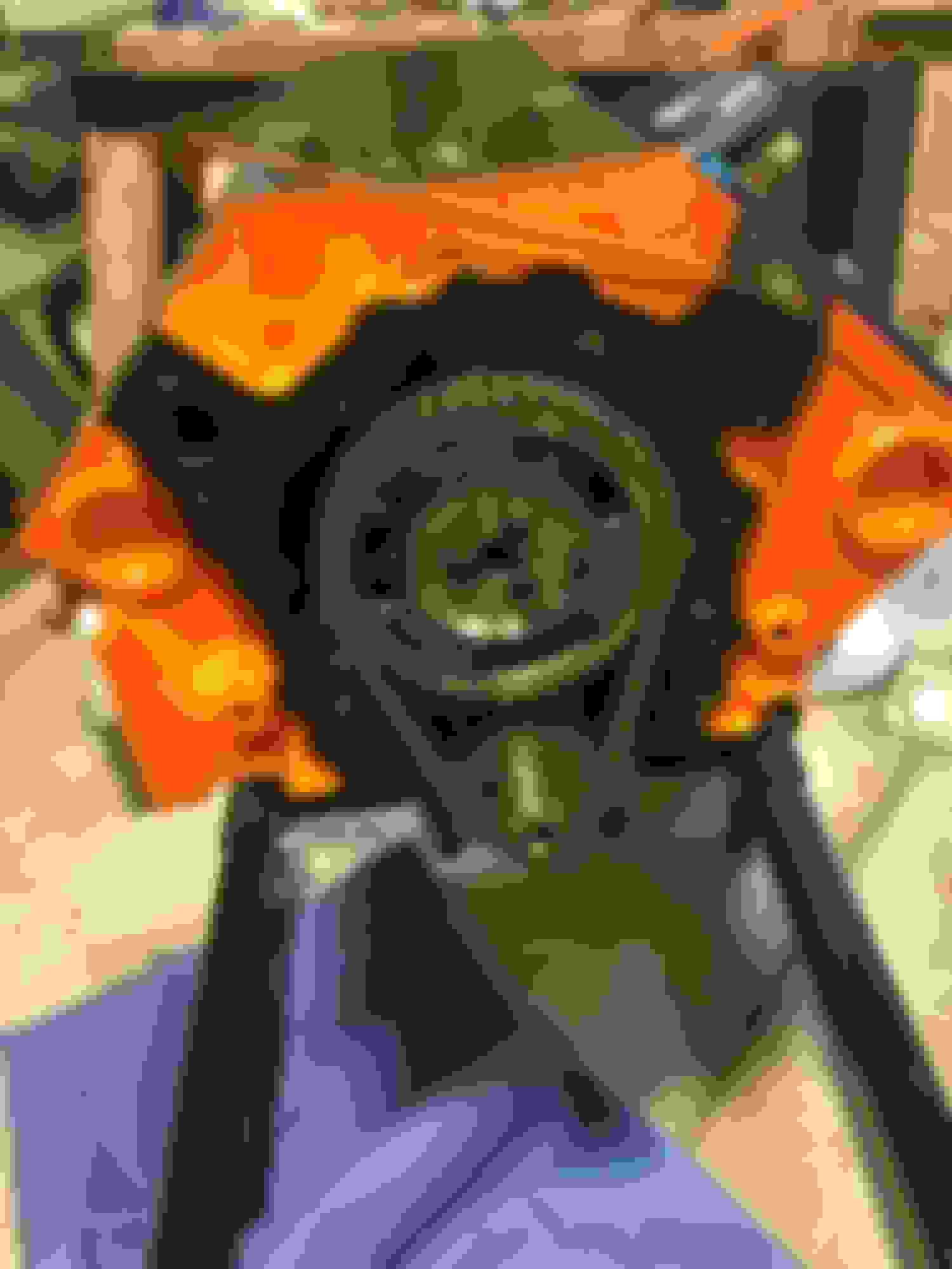
Block after decking. Once we reassemble, we will recheck the piston to deck height and see if we are where we want to be.
Was planning to rig up a system to allow us to wash the block out after the machine work. Outside water was shut off for the winter and hose blown dry and put away. But then we got this really nice break in the weather and decided to bring the block out of the shed and wash it down in the driveway. Looks good now.
Soaping it down.
Brushing
it clean.
Ready to oil it down and wrap it up until New Year's Eve. Reassembly party. LOL
So we found a little time on New Year's Eve to get things back together.
The Lt. works on getting the cam back in.
Crankshaft in.
Torquing the mains.
Lifters lubed up and in.
Now we're ready to recheck the piston to deck height. My machinest buddy is planning to bring his bridge micrometer over on Tue evening. Once we have those measurements we can decide on the head gasket thickness to set the quench.
Pretty much what Jorlain said.
My preferred gasket has always been the Victor Reinz/Cometic/Clevite 5746. It's .026" x 4.125". https://www.summitracing.com/int/par...5746/overview/
While the quench gets to less than .040", we've had no trouble with .037" on a 355 with hypereutectic pistons.
Still, I would have thought that your shop might have squared the block.
Last edited by skinny z; Jan 18, 2017 at 07:10 PM.
The shop only decked the block, they did not align hone the mains. In their defense we did not ask them to. In 20/20 hindsight I might choose next build to have that done in the initial stages. Live and learn. But it is a street engine I keep reminding myself.
They say the only dumb question is the one you don't ask. So here goes.
Are head gaskets always sold in pairs? If they are not, does it make any sense to go with .26 on the one side and .28 on the other?
The head gaskets do not come in pairs. Most of the time they're sold individually (unless you're buying a kit of some sort).
I personally prefer to keep things the same on both sides, so the idea of using two separate gaskets hasn't really come to mind previously... That said, I don't think it'd cause you any heartbreak, as you're just balancing the difference to try and get the quench similar on both sides.
Edit: I have heard rumors that the advertised .026 Victor Reinz\Clevite gasket is actually .028, though. So it may or may not make a difference.
Considering that an undecked block, such as one that I recently sold, had deck clearances ranging from .026" to .036", I'd say it's a safe bet that sticking with one gasket PN will be just fine. Keep in mind while you're calculating your compression ratio and further down the road, tuning, that there's a slight difference between the two sides and make your moves accordingly.
Well we are leaning toward going with the two different gaskets in order to equalize the difference in the heads. The only thing that is giving us pause is the quality of the two gaskets. If the difference in quality is noticeable I would rather have the slightly difference in quench but if the quality between GMPP and Victor is negligible, then we will prolly go with the different heights to bring both sides to .0395 and .040.
The other question that I am sort of blanking on since it has been awhile for me, is are we going to go with a gasket with a bore of 4.00 or something slightly larger? I figured we wouldn't want the 4.00 because it would overhang the chamfer into this cylinder. But then again I am not sure it would matter, and if we did go bigger, what size is appropriate?
What is your cylinder bore?
The GMPP .028" gasket that I'm familiar with is 4.00". Not suitable for any overbore. The 5647 Clevite/Reinz is 4.120" (or 4.125").
As I stated earlier, I'd use the same gasket, both sides. You can drive yourself nuts trying to dissect something like this. In the end, it's not the ultimate build. This isn't to say that you don't need to care in your assembly and ensure that all the parts are compatible but the differences between side to side (or cylinder to cylinder as the case might be) isn't a new thing with these engines and trying to massage it to the nth degree will yield a improvement in performance that would be difficult to measure.
Either gasket would be suitable with the Victor Reinz being slightly thinner albeit it with a larger bore.
Ok, sounds like we're going to go with the same gasket on both sides. Is there a disadvantage to the Victor Reinz having a larger bore than the engine? Is there a disadvantage with the GMPP being "tight" to the piston bore?
At this stage of the game the head gasket is generally used to zero in the final compression ratio and piston to head clearance but...
The bore diameter and thickness of the gasket leave behind a crevice volume. The idea is to have as little volume as possible. Comparing the two, the VR has a volume of about .346 cubic inches. The GMPP about .352. Seeing as most compression ratio calculators don't include the crevice volume at all, then the differences between the two are inconsequential.
As for zeroing in the final CR and quench, the two gaskets also yield similar results. The VR netting a slightly higher CR by about .02.
It's pretty much a toss up.
I can recommend the VR 5746 as I've used them in several builds with zero issues. They are also somewhat less expensive although back when I started this game, the GMPP gasket was almost double the cost.