When you click on links to various merchants on this site and make a purchase, this can result in this site earning a commission. Affiliate programs and affiliations include, but are not limited to, the eBay Partner Network.
How to wire a 4th gen F-body fuel tank into a 3rd gen F-body
LTX and LSXPutting LT1s, LS1s, and their variants into Third Gens is becoming more popular. This board is for those who are doing and have done the swaps so they can discuss all of their technical aspects including repairs, swap info, and performance upgrades.
Re: How to wire a 4th gen F-body fuel tank into a 3rd gen F-body
Originally Posted by QwkTrip
Sorry, my apologies. Somehow I carried that error through all my build documentation for many years and 2 different fuel systems. Not sure how I did that.
I do use 611203 on the hose drop from tank to my hard lines. I remember having a special part number of shorter length at the fuel tank bulkhead to get the hose to route nicely. Now I don't know what is that part number if my old documentation is wrong.
THe other will work for the vent if you don't use the factory contraption on the tank.
Re: How to wire a 4th gen F-body fuel tank into a 3rd gen F-body
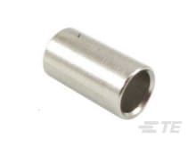
Other than a Ferrule... several Companies produce Sleeves/ Spacers to go between a smaller Gauge Wire and a Larger Terminal.
It is never ideal, but is considered acceptable.
Here is an example from TE for Deutsch Connectors (NOTE: I have never used any of these from TE): HyperLink
Re: How to wire a 4th gen F-body fuel tank into a 3rd gen F-body
Does anyone have a source for AC Delco 25319676 (or compatible) that isn't $100? When I got my car running I of course ordered an incorrect sender and didn't check the resistance so now I've got my tank out again to fix it for hopefully the last time. The prices I'm finding for these things just seem ridiculous for what they are.
Re: How to wire a 4th gen F-body fuel tank into a 3rd gen F-body
That Parts appears to be recently discontinued.
If that is indeed correct, and aftermarket options are more expensive than your budget allows for...
I recommend re-reading the section of this Thread that goes over replacing the "Card" or Electrical Contact Assembly.
I would try using some Junk-Yard (or what the Kids today call: "Auto Recyclers") Electrical Contact Assemblies, swapped into your existing Fuel Pump Module and Sending-Unit Assembly.
Re: How to wire a 4th gen F-body fuel tank into a 3rd gen F-body
Originally Posted by Grant2k
Does anyone have a source for AC Delco 25319676 (or compatible) that isn't $100? When I got my car running I of course ordered an incorrect sender and didn't check the resistance so now I've got my tank out again to fix it for hopefully the last time. The prices I'm finding for these things just seem ridiculous for what they are.
I found a compatible Herko unit on eBay for < $40 each. Herko FC31, 0-90 ohm fuel level sender
Re: How to wire a 4th gen F-body fuel tank into a 3rd gen F-body
Originally Posted by Grant2k
Does anyone have a source for AC Delco 25319676 (or compatible) that isn't $100?
It's always been ridiculously expensive. It comes with two units so people typically sell one for about 1/2 to 2/3 the price to somebody that doesn't want to spend full amount.
Re: How to wire a 4th gen F-body fuel tank into a 3rd gen F-body
Originally Posted by QwkTrip
It's always been ridiculously expensive. It comes with two units so people typically sell one for about 1/2 to 2/3 the price to somebody that doesn't want to spend full amount.
Back when I bought a few from Herko units from eBay, pricing was particularly bad for the GM part (want to say > $300), if you could find it anywhere. Supply chain woes I guess. Right now, GM Parts Direct has it for $203. All the other usual places are sold out. So if you want a GM unit, either buy it at the increased markup or hope for more to be produced and sold... which is questionable given this part was last used on cars made in 1997.
Re: How to wire a 4th gen F-body fuel tank into a 3rd gen F-body
The one I have in the car currenly is a Herko and now that I've tested it I can say it is actually very accurate, it's just the wrong one which is my fault.
I should have it today so I'll see what the resistance is on it. Maybe it's wrong and I screwed up again but at least it will be knowledge gained on another part #.
Re: How to wire a 4th gen F-body fuel tank into a 3rd gen F-body
Originally Posted by Grant2k
The one I have in the car currenly is a Herko and now that I've tested it I can say it is actually very accurate, it's just the wrong one which is my fault.
I should have it today so I'll see what the resistance is on it. Maybe it's wrong and I screwed up again but at least it will be knowledge gained on another part #.
I just ordered one from Amazon and the review said it worked for 3rd gen.
Re: How to wire a 4th gen F-body fuel tank into a 3rd gen F-body
How does the return work? I'm using a tbss intake so it has an inlet but no outlet. I blew into the return and it seems to be sealed is the regulator on the return side?
Re: How to wire a 4th gen F-body fuel tank into a 3rd gen F-body
With 4th gen fuel tank, the fuel pressure regulator is integral to the fuel bucket inside the fuel tank. Use a 4th gen F-body fuel filter and tee back to tank immediately after the filter. This will support up to 270 L/hr fuel flow. If you want to use an external pressure regulator, then you'll need to gut the stock in-tank regulator so it is full flow.
I don't know what the Trailblazer SS manifold has for fuel rails and pressure regulator.
Re: How to wire a 4th gen F-body fuel tank into a 3rd gen F-body
Originally Posted by Leon82
How does the return work? I'm using a tbss intake so it has an inlet but no outlet. I blew into the return and it seems to be sealed is the regulator on the return side?
I'm using a C5 filter/regulator. Maybe not the absolute best but certainly the easiest solution. You can just remove the 4th gen regulator from the sending unit assembly.
Re: How to wire a 4th gen F-body fuel tank into a 3rd gen F-body
Originally Posted by QwkTrip
With 4th gen fuel tank, the fuel pressure regulator is integral to the fuel bucket inside the fuel tank. Use a 4th gen F-body fuel filter and tee back to tank immediately after the filter. This will support up to 270 L/hr fuel flow. If you want to use an external pressure regulator, then you'll need to gut the stock in-tank regulator so it is full flow.
I don't know what the Trailblazer SS manifold has for fuel rails and pressure regulator.
Re: How to wire a 4th gen F-body fuel tank into a 3rd gen F-body
Originally Posted by Leon82
It just has an inlet. No regulator
If it indeed has no regulator than you could possibly leave the 4th gen regulator in place and tee back after the filter like QwkTrip suggested. I don't see why that wouldn't work.
Re: How to wire a 4th gen F-body fuel tank into a 3rd gen F-body
Originally Posted by Grant2k
If it indeed has no regulator than you could possibly leave the 4th gen regulator in place and tee back after the filter like QwkTrip suggested. I don't see why that wouldn't work.
Re: How to wire a 4th gen F-body fuel tank into a 3rd gen F-body
Originally Posted by Leon82
It came today. The ohm range is correct. It even has a few different wiring diagrams.
The white plastic piece on the Amazon sender wasn't the exact same height. the fork was too high for a direct fit so I swapped the card into the existing bucket piece. The sender arm contacts are very thin so be careful.
Re: How to wire a 4th gen F-body fuel tank into a 3rd gen F-body
Most people will string it under the car because it's more convenient. I've heard of some people running it inside the tube of their subframe connector. I went through the interior because I didn't like the idea of laying wire under the car and associated hazards with that.
My method was kind of hack because I didn't know better at the time. If I did it again then I would do like suggested earlier (splicing into existing wires) but the crimp tool will cost plenty and you may never have a use for it again.
Re: How to wire a 4th gen F-body fuel tank into a 3rd gen F-body
That's exactly what I did too. Apparently we both found the same mysterious hole in the firewall that's filled by a rubber plug. I'm guessing the hole was for Camaro with cable driven speedo but that's just a guess.
Looking at the C100 pinouts shown earlier in this thread, it appears the stock 14 AWG fuel pump wire uses a Metri-Pack 630 size terminal. With a terminal that large it would be possible to remove the stock wire from C100 and replace with a new larger wire. But you'd have to deal with all the sealant goo inside the connector.
Re: How to wire a 4th gen F-body fuel tank into a 3rd gen F-body
Wiring under the length of the vehicle should try to be avoided...
Especially anything carrying a high current, like a Positive Battery Cable.
If something gets ran over and hits a Positive Battery Cable...
You are going to have a bad day.
Re: How to wire a 4th gen F-body fuel tank into a 3rd gen F-body
Not really a wiring question but did you leave the purge contraption on the tank? It looks like the center vent piece on the pump assembly is blocked because I put a hose on it and try to blow into it and there's no flow. The tee with the big and small hose seem to vent. What's the vent setup for running it in the third gen?
Re: How to wire a 4th gen F-body fuel tank into a 3rd gen F-body
The Goal here is to crimp the Conductor Strands sufficiently enough that they resemble one sold chunk of copper when examining the cross-section that you created.
From the images, it looks great!
I would ideally like to see a Terminal used that is at least a small amount longer...
But it is not the end of the world.
If the cross-section looks just as solid in real-life as it does in the Image... you are good to go!
Re: How to wire a 4th gen F-body fuel tank into a 3rd gen F-body
Originally Posted by QwkTrip
Cross-section cut of 10 AWG and 2 x 14 AWG crimped together. Is this good enough for a home brew solution?
I'll tell you what I did after some feedback.
a good way of understanding the capability is to look up on a stranded wire table the circular area and corresponding resistance per foot... you will find that two 14 awg wires only have about 80% of the cross sectional area of a single 10 awg. resistance is also proportionally higher as you would expect
Re: How to wire a 4th gen F-body fuel tank into a 3rd gen F-body
Originally Posted by alan91z28
a good way of understanding the capability is to look up on a stranded wire table the circular area and corresponding resistance per foot... you will find that two 14 awg wires only have about 80% of the cross sectional area of a single 10 awg. resistance is also proportionally higher as you would expect
Yes, but both wire sizes are still way overkill for what's needed. The difference of voltage losses in wire is literally negligible at 12A current my pump runs at. Each connection in the wire harness is far more detrimental than choice of wire size. If you want good voltage at the pump then focus on reducing count of connections in the wire runs.
Re: How to wire a 4th gen F-body fuel tank into a 3rd gen F-body
Originally Posted by vorteciroc
If the cross-section looks just as solid in real-life as it does in the Image... you are good to go!
Thanks, that was my gut feel too but I have no experience studying crimps. But it seemed the cross-section had good fill, and the wire wasn't pinched at the lead-in to the crimp.
I'll tell you what I did. I have a Delphi double wire crimper (12040070) I bought by accident not realizing what it was and never used it. Dug it out of the drawer and paired it with an Amplivar thru splice (63562-1) and the crazy thing turned out surprisingly good! I will strain relieve it with ES-2000 semi-rigid dual wall shrink wrap.
I had to squeeze the bajeebers out of the crimper but it only has to last 4 more times and I will have gotten a lifetime of use out of it. LOL!
Re: How to wire a 4th gen F-body fuel tank into a 3rd gen F-body
Originally Posted by QwkTrip
Yes, but both wire sizes are still way overkill for what's needed. The difference of voltage losses in wire is literally negligible at 12A current my pump runs at. Each connection in the wire harness is far more detrimental than choice of wire size. If you want good voltage at the pump then focus on reducing count of connections in the wire runs.
sure np, if you are only then looking for a comment on the quality of the crimp, i would say the pics of your crimp is reasonable and should give good practical service for you.
the reason i say reasonable is most hand tools do not produce true quality production type results. there are hand tools (Rennsteig for example) that can do this but as you would expect they have dies that are very specific to the crimp style and wire size and correspondingly very expensive for an individual. a true factory crimp results in the crimped area almost looking like a solid core upon cutting a cross section. the picture in the link below gives a good indication of this type of production crimp result
for very large cable sizes where large safety factors of cable size vs current can't be achieved failure to have a true good crimp can result in local overheating and failure right at the crimp due to a high resistance connection
wire harness development is always a challenge for us in the hobby as usually we are using less than ideal tools
Last edited by alan91z28; Apr 14, 2023 at 06:50 AM.
Re: How to wire a 4th gen F-body fuel tank into a 3rd gen F-body
Thanks for the insight, Alan. I appreciate it!
Got any home brew solutions of your own for splicing 10 AWG to 2 x 14 AWG? Once things get up to larger than 10 AWG it seems the tools get pretty expensive. I've thought about maybe trying to do a 10 AWG butt splice but unfortunately I don't have the tool for that and not sure what to buy and how much cost that would be.
Basically what I'm trying to do is replicate the "vorteciroc fuel pump pass-thru" at C313 connector described earlier in this thread.
Re: How to wire a 4th gen F-body fuel tank into a 3rd gen F-body
Originally Posted by QwkTrip
Thanks for the insight, Alan. I appreciate it!
Got any home brew solutions of your own for splicing 10 AWG to 2 x 14 AWG? Once things get up to larger than 10 AWG it seems the tools get pretty expensive. I've thought about maybe trying to do a 10 AWG butt splice but unfortunately I don't have the tool for that and not sure what to buy and how much cost that would be.
Basically what I'm trying to do is replicate the "vorteciroc fuel pump pass-thru" at C313 connector described earlier in this thread.
these molex splices work well if you get a good matching size (they come in different sizes)... they work best with their crimper which unfortunately is quite expensive... however the terminals are cheap so you could try them with a crimper you likely already have (ie the y/b/r barrel type) and cross section to verify results. they are nice and compact and can easily be sealed with good quality thick heat shrink that has internal sealant upon application and stiff enough to provide good strain relief
also you can look at places like mcmaster-carr as they have some heat shrink insulated type splices with solder flow... they work reasonably well compared to some other choices... i like the molex better though as it is more robust and much heavier gauge barrel
Last edited by alan91z28; Apr 14, 2023 at 03:42 PM.
Re: How to wire a 4th gen F-body fuel tank into a 3rd gen F-body
Originally Posted by QwkTrip
Lot of links to good reading in that link. Thanks!!
This will keep me busy for a while trying to absorb info.
here is also for completeness the link to the molex site which is good at also specifying all sorts of sizes, etc and also the preferred tooling part numbers for crimping
Re: How to wire a 4th gen F-body fuel tank into a 3rd gen F-body
The Circular Mil Area Chart that you (@QwkTrip) made is by far the best made Post that I feel any Member here could have put together on their own.
Originally Posted by QwkTrip
WIRE SPLICES
Below is a splice selection guide I created that is based on data from TE Connectivity datasheets for AMPLIVAR wire splices.
I found everything at the TE Connectivity website (which is awesome by the way). If you're interested to investigate for yourself then search for these documents:
Document 82561, Calculating circular Mil area for a splice
Document 114-2088, Crimp specifications for AMPLIVAR splices
The key to all this is knowing what is CMA for each wire that you want to splice together. CMA is Circular Mil Area and it is a large number that is calculated from the physical geometry of the wire. Here is a Wiki link if you want to learn more, https://en.wikipedia.org/wiki/Circular_mil
Now if you skipped the Wiki link, and you skipped reading any of the documents I provided, then it's your lucky day because I did all the hard work for you and created a simple worksheet to knock this out quick.
Step 1: Find the CMA range for the wires you want to join together. I have provided data for common TXL type automotive wire. Your wire might vary some depending on the number of strands but it will be reasonably close.
Example: If you want to join four 22 AWG wires then walk across the top row to 22 (x1) AWG. Then walk down the left column to 22 AWG (x3). The cell where those two cross (2800) is the total CMA of the four wires.
Step 2: Select a splice part number that is appropriate for the sum total CMA range of the wires you want to join.
Example: The CMA range from Step 1 was (2800). Any part number splice can be used that has a minimum CMA smaller than that (listed in left-hand column), and a maximum CMA larger than that (listed in top row). That gives you a lot of choices but the best area to land is probably at the intersection of 600 left, and 3000 top (it is desirable that the crimp be as full as possible). A 5 or 7 serration brass splice would be a good choice (part numbers 42076 if going thru the splice, or 62000-1 if all wires coming in from same side of splice).
Here is an instructional video by HP Academy that explains how to make the splice.
Many people who do this type of work professionally (including Myself) will develop a sense of what to use for an un-insulated Splice-Terminal...
and corresponding Wire Gauge for needed Wires to be used.
...What I am trying to say that experience for most of us has mostly replaced the excellent chart that is Posted above...
In combination with the following two test for reassurance (when felt it is needed) Amperage Clamping, and Resistance Testing.
All I am going to further say is keep up the Amazing work!
I really love to see it all!!!
And the "Shout-Out" gave me a massive smile, so thanks again!
Re: How to wire a 4th gen F-body fuel tank into a 3rd gen F-body
Originally Posted by vorteciroc
All I am going to further say is keep up the Amazing work!
I really love to see it all!!!
And the "Shout-Out" gave me a massive smile, so thanks again!
You're always incredibly kind.
When I sat down to learn about wiring I did not know the deep hole I was jumping in. I can figure out a lot of things but not everything and that's where you've been stepping in to remove my frustrations when I get stuck. Many thanks for that! I would have thrown in the towel ages ago if you hadn't helped me get past those road blocks. My way of saying "thanks" is to kick out these tech threads so everyone can benefit from it. It's a relationship that's working really well and everybody ends up a winner!
Re: How to wire a 4th gen F-body fuel tank into a 3rd gen F-body
I finally got around to testing the wiring. I hooked the green Terminator wire up to the tan and white wire I traced back to the dashboard. As soon as I turned the key on the pump came on.
Re: How to wire a 4th gen F-body fuel tank into a 3rd gen F-body
Sorry to bring up an old thread, but the C313 pass thru harness for the fuel injected cars.....is it the same as the carbed cars, less one wire?
Is the housing the same?
Re: How to wire a 4th gen F-body fuel tank into a 3rd gen F-body
I don't know. I notice in this '85 Camaro gauges wiring diagram that it is designated as C300 connector, not C313. That implies to me that it is different in some way. I doubt the connector names are random, they all likely have meaning as to their purpose but I don't know how to find that engineering standard.
Re: How to wire a 4th gen F-body fuel tank into a 3rd gen F-body
Originally Posted by QwkTrip
If you have an earlier carbureted car, then maybe you can pull back the carpet to take a peak and tell us what you find?
My �84 LG4/T5 did not have a rear bulkhead connector. I had to add one from a 4th gen that I sourced the fuel tank from. All of the wiring to the rear of the car was in one harness bundle and connected to the C2XX (can�t remember the exact number), including the lights, ground, and the fuel pump. The C3XX (see above) that I used has two plugs on the aft side of the bulkhead connector which allowed me to run the fuel pump trigger and the fuel level gauge to one, and the rear ABS sensors to the other. The seven wires are 20 ga which made it easy to lay them flat inside the bulkhead fitting. The battery is in the back and the fuel pump power and ground are connected to distribution blocks near the battery so there are no high amp feeds through the bulkhead.
Re: How to wire a 4th gen F-body fuel tank into a 3rd gen F-body
Originally Posted by soloc4
My �84 LG4/T5 did not have a rear bulkhead connector. I had to add one from a 4th gen that I sourced the fuel tank from. All of the wiring to the rear of the car was in one harness bundle and connected to the C2XX (can�t remember the exact number), including the lights, ground, and the fuel pump.
With the stock '84, how did the fuel level sender wire get outside the car to the fuel tank?
Re: How to wire a 4th gen F-body fuel tank into a 3rd gen F-body
Originally Posted by QwkTrip
With the stock '84, how did the fuel level sender wire get outside the car to the fuel tank?
With the steel tank, the pump and float shared a common ground at the tank module with the pump power and level sender wires as part of the harness bundle along the driver�s side door jam. What surprised me the most was that I found a couple of the wires were solid core aluminum. All of the wiring in the car was replaced with TXL, including the above mentioned bundle. I have had zero electrical issues since.


 I'm guessing the hole was for Camaro with cable driven speedo but that's just a guess.