
There's Something Wrong With Your Head


Joined: Mar 2006
Posts: 4,370
Likes: 19
Car: 1973 Datsun 240Z/ 1985 S-15 Jimmy
Engine: Turbo LX9/To be decided
Transmission: 5-speed/T-5
Axle/Gears: R200 3.90/7.5" 3.73
Re: There's Something Wrong With Your Head
I'm aware it doesn't matter where the sensor is. It matters how the trigger is placed. It doesn't specify where the engine is at when that trigger is mounted in that link unless I missed it.
In your bottom picture you have the engine at TDC, and the sync notch place there?
In your bottom picture you have the engine at TDC, and the sync notch place there?
The ONLY thing that matters is that the sync notch passes the sensor when the crank is at the correct angle in relation to TDC #1. The wheel gets clocked to a position to make this happen.
I'll hold your hand here...
The sync notch is placed at 10* after the #1 notch passes the sensor at TDC for cyl #1.
So in the case of my Jimmy the sync notch was approximately 8:30ish when cyl #1 was at TDC, and in the Datsun the same sync notch is at about 1:45 when cyl #1 is at TDC. Are you getting what I'm saying here? You have to relate WHERE to put the sync notch in relation to cyl #1 TDC and where you have the sensor placed.
It was just co-incidence that the sync notch HAPPENED to be somewhat inline with the timing mark on the Datsun, but was not planned nor important for it to be there.

Joined: Mar 2011
Posts: 6,287
Likes: 41
From: Northwest Ohio
Car: 1991 Camaro RS
Engine: Lq4 6.0 SBE s485 turbo E85
Transmission: Fsi th400 stage 4. TSI 5500 st
Axle/Gears: Strange S60 4:10s
Re: There's Something Wrong With Your Head
Did you make up that reluctor wheel yourself or have a shop do it? Im worried about making one up because it I feel it wouldn't come out perfect, as in the shape of the circle. Also with a new wheel between the damper and the pulley, did you have to literly shim each pulley out to make up for the difference? Thanks!
Joined: Mar 2006
Posts: 4,370
Likes: 19
Car: 1973 Datsun 240Z/ 1985 S-15 Jimmy
Engine: Turbo LX9/To be decided
Transmission: 5-speed/T-5
Axle/Gears: R200 3.90/7.5" 3.73
Re: There's Something Wrong With Your Head
Did you make up that reluctor wheel yourself or have a shop do it? Im worried about making one up because it I feel it wouldn't come out perfect, as in the shape of the circle. Also with a new wheel between the damper and the pulley, did you have to literly shim each pulley out to make up for the difference? Thanks!
Yes, I had to space out the pulleys. However, I only needed to make a spacer for the water pump pulley and the power steering, and even the power steering set-up only needed one spacer (not two like it should have needed), for a reason I can not recall right now, and the alternator/tensioner pulleys mounts was custom anyway.
Spacing the driven accessories is not that difficult. In most cases it can literally be done with washers, though I do prefer to make spacers with more support than that in most cases.
You could do it like I did on the Datsun, and place the wheel in front of the crank pulley, but that does require a spacer to be between the trigger wheel and the inside of the pulley for best results. I used a longer crank pulley here to use it as a centering device, and retainer. Good thing too, because I had the trigger wheel come loose a couple times due to the outer ring of the harmonic balancer, which is also the pulley rubbing against the trigger wheel causing it to loosen off, which caused the 6mm threaded holes in the pulley to deform. This forced me to eventually drill them out to 8mm and and recess the back of the trigger wheel to allow the outer ring to do it job, without rubbing on the trigger wheel. There was no way to easily mount the trigger wheel behind the Datsun's pulley due to the design, which is more like what you'd find on a FWD 660, as a reference. Both the harmonic balancer and pulley are integrated into one.
I thought about producing the trigger wheels at one point, but there wasn't enough interest.
Joined: Mar 2011
Posts: 6,287
Likes: 41
From: Northwest Ohio
Car: 1991 Camaro RS
Engine: Lq4 6.0 SBE s485 turbo E85
Transmission: Fsi th400 stage 4. TSI 5500 st
Axle/Gears: Strange S60 4:10s
Re: There's Something Wrong With Your Head
I talked to the machine shop about this the other day when ordering some parts for the build. They have a mil there and can make it up. Would cost around 80 bucks to make the wheel and notch it correctly. I suppose that isn't a bad price if its done right and works.
I am suppose to assemble my short block this upcoming weekend. Im taking the damper to them on Wednesday and letting them see that and the template I have so they can give me a more definite price.
I don't think spacing out the accessory's would be to bad either. I only have a Alt, tentioner,WP and PS pump on the car. Thanks for the input sixshooter, stuff is seeming easier the more I learn about this DIS system.
Joined: Mar 2006
Posts: 4,370
Likes: 19
Car: 1973 Datsun 240Z/ 1985 S-15 Jimmy
Engine: Turbo LX9/To be decided
Transmission: 5-speed/T-5
Axle/Gears: R200 3.90/7.5" 3.73
Re: There's Something Wrong With Your Head
I talked to the machine shop about this the other day when ordering some parts for the build. They have a mil there and can make it up. Would cost around 80 bucks to make the wheel and notch it correctly. I suppose that isn't a bad price if its done right and works.
I am suppose to assemble my short block this upcoming weekend. Im taking the damper to them on Wednesday and letting them see that and the template I have so they can give me a more definite price.
I don't think spacing out the accessory's would be to bad either. I only have a Alt, tentioner,WP and PS pump on the car. Thanks for the input sixshooter, stuff is seeming easier the more I learn about this DIS system.
I am suppose to assemble my short block this upcoming weekend. Im taking the damper to them on Wednesday and letting them see that and the template I have so they can give me a more definite price.
I don't think spacing out the accessory's would be to bad either. I only have a Alt, tentioner,WP and PS pump on the car. Thanks for the input sixshooter, stuff is seeming easier the more I learn about this DIS system.

Joined: Mar 2006
Posts: 4,370
Likes: 19
Car: 1973 Datsun 240Z/ 1985 S-15 Jimmy
Engine: Turbo LX9/To be decided
Transmission: 5-speed/T-5
Axle/Gears: R200 3.90/7.5" 3.73
Re: There's Something Wrong With Your Head
No.
Well, at least not without all of the information.
Well, at least not without all of the information.
Member
iTrader: (1)
Joined: Feb 2008
Posts: 463
Likes: 0
From: Connecticut
Car: 1987 Chevrolet Camaro
Engine: 2.8L V6 MPFI
Transmission: 700R4
Axle/Gears: 10 Bolt
Re: There's Something Wrong With Your Head
All the information is there. Sensor is at TDC of crank. First notch is 10* After TDC, second notch or the sync is 10* after that or 20* from TDC. Than 5 notches 60 degrees all around from first notch.
Joined: Mar 2006
Posts: 4,370
Likes: 19
Car: 1973 Datsun 240Z/ 1985 S-15 Jimmy
Engine: Turbo LX9/To be decided
Transmission: 5-speed/T-5
Axle/Gears: R200 3.90/7.5" 3.73
Re: There's Something Wrong With Your Head

With your description, no that is not correct. Go back and read the megamanual link I posted on the previous page. The correct set-up information is there.
Member
iTrader: (1)
Joined: Feb 2008
Posts: 463
Likes: 0
From: Connecticut
Car: 1987 Chevrolet Camaro
Engine: 2.8L V6 MPFI
Transmission: 700R4
Axle/Gears: 10 Bolt
Re: There's Something Wrong With Your Head
According to the megamanual, the notch right next to the sync notch coincides with TDC.
So when the first cylinder is at TDC the sensor should be in the middle of the first notch? So my first notch should be the stock harmonic balancer timing mark and 10 degrees after TDC should be my sync notch.
That's how you have it set-up in that last picture.
Correct?
So when the first cylinder is at TDC the sensor should be in the middle of the first notch? So my first notch should be the stock harmonic balancer timing mark and 10 degrees after TDC should be my sync notch.
That's how you have it set-up in that last picture.
Correct?
Joined: Mar 2006
Posts: 4,370
Likes: 19
Car: 1973 Datsun 240Z/ 1985 S-15 Jimmy
Engine: Turbo LX9/To be decided
Transmission: 5-speed/T-5
Axle/Gears: R200 3.90/7.5" 3.73
Re: There's Something Wrong With Your Head
As I said, it was co-incidence that the sync notch happened to nearly line up with my timing mark, PURE CO-INCIDENCE. The clocking of the trigger wheel is relative to the location of the sensor. It's actually the leading edge of the notch where the sensor should line up to, but this is also why I make my mounts adjustable to be able to make the base timing exactly where it needs to be.

Moderator
iTrader: (1)
Joined: Mar 2002
Posts: 18,432
Likes: 234
From: Chasing Electrons
Car: check
Engine: check
Transmission: check
Re: There's Something Wrong With Your Head
The trailing edge of the notch is the trigger point.
Chris, in your drawing you have it set up to trigger at 10* after TDC. Need to rotate the trigger wheel clockwise until the tip of the sensor is at the trailing edge of the sync notch.
That will have the 1&4 notch pass under the sensor at 10* BTDC.
If you get it a little off that can be corrected in the calibration via the initial SA setting.
RBob.
Member
iTrader: (1)
Joined: Feb 2008
Posts: 463
Likes: 0
From: Connecticut
Car: 1987 Chevrolet Camaro
Engine: 2.8L V6 MPFI
Transmission: 700R4
Axle/Gears: 10 Bolt
Re: There's Something Wrong With Your Head
The trailing edge of the notch is the trigger point.
Chris, in your drawing you have it set up to trigger at 10* after TDC. Need to rotate the trigger wheel clockwise until the tip of the sensor is at the trailing edge of the sync notch.
That will have the 1&4 notch pass under the sensor at 10* BTDC.
If you get it a little off that can be corrected in the calibration via the initial SA setting.
RBob.
Chris, in your drawing you have it set up to trigger at 10* after TDC. Need to rotate the trigger wheel clockwise until the tip of the sensor is at the trailing edge of the sync notch.
That will have the 1&4 notch pass under the sensor at 10* BTDC.
If you get it a little off that can be corrected in the calibration via the initial SA setting.
RBob.
"In a 6-cylinder application, the evenly spaced notches coincide with TDC. The sync pulse notch coincide with 10° after TDC for the #1 cylinder."
This is what you're saying my wheel should look like because of my sensor location?

Moderator
iTrader: (1)
Joined: Mar 2002
Posts: 18,432
Likes: 234
From: Chasing Electrons
Car: check
Engine: check
Transmission: check
Re: There's Something Wrong With Your Head
It has to do with the cranking SA. Which is supposed to be at 10* BTDC.
To do this need to advance the trigger wheel so that the trailing edge of the 1&4 notch passes under the sensor tip at 10* before the cylinder actually reaches TDC. Being that the sync notch is at 10* past the 1&4 notch, makes it easy to line it up.
Be sure to align to the trailing edge of the notch, not the middle or leading edge.
Someplace in this thread I posted a picture of what the sensor signal to the ICM looks like. The opening of the notch causes the signal to rise, this arms the zero crossing detector.
When the trailing edge of the notch arrives the signal quickly falls triggering the module.
Note that if the sensor signal is reversed the ICM won't trigger.
RBob.
Joined: Mar 2006
Posts: 4,370
Likes: 19
Car: 1973 Datsun 240Z/ 1985 S-15 Jimmy
Engine: Turbo LX9/To be decided
Transmission: 5-speed/T-5
Axle/Gears: R200 3.90/7.5" 3.73
Re: There's Something Wrong With Your Head
Uhh, wait, RBob, you have it wrong.
You have to set the notch that coincides with TDC in line with the sensor at TDC. The Sync notch is 10 degrees later. See the picture of the installation on my Datsun's engine on the previous page. The exposed notch is that nearly lines up with the yellow timing mark is the sync notch, the #1 TDC notch is under the sensor. This gives the same 10* BTDC base timing that is seen on the OEM installations.
You have to set the notch that coincides with TDC in line with the sensor at TDC. The Sync notch is 10 degrees later. See the picture of the installation on my Datsun's engine on the previous page. The exposed notch is that nearly lines up with the yellow timing mark is the sync notch, the #1 TDC notch is under the sensor. This gives the same 10* BTDC base timing that is seen on the OEM installations.
Last edited by Six_Shooter; Feb 17, 2014 at 10:26 AM.
Member
iTrader: (1)
Joined: Feb 2008
Posts: 463
Likes: 0
From: Connecticut
Car: 1987 Chevrolet Camaro
Engine: 2.8L V6 MPFI
Transmission: 700R4
Axle/Gears: 10 Bolt
Re: There's Something Wrong With Your Head
It has to do with the cranking SA. Which is supposed to be at 10* BTDC.
To do this need to advance the trigger wheel so that the trailing edge of the 1&4 notch passes under the sensor tip at 10* before the cylinder actually reaches TDC. Being that the sync notch is at 10* past the 1&4 notch, makes it easy to line it up.
Be sure to align to the trailing edge of the notch, not the middle or leading edge.
Someplace in this thread I posted a picture of what the sensor signal to the ICM looks like. The opening of the notch causes the signal to rise, this arms the zero crossing detector.
When the trailing edge of the notch arrives the signal quickly falls triggering the module.
Note that if the sensor signal is reversed the ICM won't trigger.
RBob.
To do this need to advance the trigger wheel so that the trailing edge of the 1&4 notch passes under the sensor tip at 10* before the cylinder actually reaches TDC. Being that the sync notch is at 10* past the 1&4 notch, makes it easy to line it up.
Be sure to align to the trailing edge of the notch, not the middle or leading edge.
Someplace in this thread I posted a picture of what the sensor signal to the ICM looks like. The opening of the notch causes the signal to rise, this arms the zero crossing detector.
When the trailing edge of the notch arrives the signal quickly falls triggering the module.
Note that if the sensor signal is reversed the ICM won't trigger.
RBob.
Thank you.
Moderator
iTrader: (1)
Joined: Mar 2002
Posts: 18,432
Likes: 234
From: Chasing Electrons
Car: check
Engine: check
Transmission: check
Re: There's Something Wrong With Your Head
Uhh, wait, RBob, you have it wrong.
You have to set the notch that coincides with TDC in line with the sensor at TDC. The Sync notch is 10 degrees later. See the picture of the installation on my Datsun's engine on the previous page. The exposed notch is that nearly lines up with the yellow timing mark is the sync notch, the #1 TDC notch is under the sensor. This gives the same 10* BTDC base timing that is seen on the OEM installations.
You have to set the notch that coincides with TDC in line with the sensor at TDC. The Sync notch is 10 degrees later. See the picture of the installation on my Datsun's engine on the previous page. The exposed notch is that nearly lines up with the yellow timing mark is the sync notch, the #1 TDC notch is under the sensor. This gives the same 10* BTDC base timing that is seen on the OEM installations.
RBob.
Joined: Mar 2006
Posts: 4,370
Likes: 19
Car: 1973 Datsun 240Z/ 1985 S-15 Jimmy
Engine: Turbo LX9/To be decided
Transmission: 5-speed/T-5
Axle/Gears: R200 3.90/7.5" 3.73
Re: There's Something Wrong With Your Head
Also I verified this to be true way back when I first built this crank trigger with a 3.1 crank in 3.1 FWD block taking the measurements to verify this exact thing.
The sync notch IS 10* ATDC relative to the #1 and 4 notch.
The way it seems to work is that it's not really referenced to #1 as far as actual spark event goes but to a cylinder later in the firing order, logic would say that it's #2 then, but I'm not totally convinced that it is. There is also the additional 60* of offset in the bin that has to be accounted for, once timing control kicks in.
You can not believe it all you want, but the fact of the matter is that the sync notch most certainly is placed at 10* ATDC relative to #1.
Last edited by Six_Shooter; Feb 17, 2014 at 11:03 AM.
Member
iTrader: (1)
Joined: Feb 2008
Posts: 463
Likes: 0
From: Connecticut
Car: 1987 Chevrolet Camaro
Engine: 2.8L V6 MPFI
Transmission: 700R4
Axle/Gears: 10 Bolt
Re: There's Something Wrong With Your Head
That's what I said, in the mega manual it says:
"In a 6-cylinder application, the evenly spaced notches coincide with TDC. The sync pulse notch coincide with 10° after TDC for the #1 cylinder."
If this is true, than the notch next to the sync notch must align to the sensor when the engine is at TDC. Which means the sync notch is 10 after TDC.
So what's correct? Sync pointed at sensor, or first notch pointed at sensor?
Last edited by XxXChrisGXxX; Feb 17, 2014 at 11:38 AM.
Moderator
iTrader: (1)
Joined: Mar 2002
Posts: 18,432
Likes: 234
From: Chasing Electrons
Car: check
Engine: check
Transmission: check
Re: There's Something Wrong With Your Head
Try this: put the engine at TDC #1, that is the damper timing mark at the 0* point on the tab.
Now put the trailing edge of the 1&4 notch at that same 0* mark of the damper & timing tab.
When is the ICM going to fire the #1 cylinder? At TDC, not 10* BTDC.
RBob.
Now put the trailing edge of the 1&4 notch at that same 0* mark of the damper & timing tab.
When is the ICM going to fire the #1 cylinder? At TDC, not 10* BTDC.
RBob.
Moderator
iTrader: (1)
Joined: Mar 2002
Posts: 18,432
Likes: 234
From: Chasing Electrons
Car: check
Engine: check
Transmission: check
Re: There's Something Wrong With Your Head
Then once the engine is running it switches to the other set of notches that are 60* from the set used during cranking.
RBob.
Joined: Mar 2006
Posts: 4,370
Likes: 19
Car: 1973 Datsun 240Z/ 1985 S-15 Jimmy
Engine: Turbo LX9/To be decided
Transmission: 5-speed/T-5
Axle/Gears: R200 3.90/7.5" 3.73
Re: There's Something Wrong With Your Head
If the sensor is set up at the sync notch with the #1 cyl at TDC, the base timing WILL be 10* early, or at 20* BTDC. Because the trigger wheel would be clocked 10* too advanced.
Last edited by Six_Shooter; Feb 17, 2014 at 11:30 AM.
Member
iTrader: (1)
Joined: Feb 2008
Posts: 463
Likes: 0
From: Connecticut
Car: 1987 Chevrolet Camaro
Engine: 2.8L V6 MPFI
Transmission: 700R4
Axle/Gears: 10 Bolt
Re: There's Something Wrong With Your Head
Guess it's time to test...soon...lol
This is from 60degreev6:
"It does not matter where you mount the pickup sensor. It matters where you put the notches.
Mount the sensor, then turn the engine to TDC of cyl.#1. Mark where the center of the sensor lines up with the damper. Now place a mark X degrees ATC where X = the BASE timing of the engine. Put the first notch centered on this mark. Put the second notch 10 degrees after the first notch. The next five notches are spaced 60 degrees apart from the FIRST notch.
When the engine starts the Bypass signal locks the ECM out and the DIS module runs on the base timing. After is starts the Bypass signal goes away and the ECM can advance the timing to whatever it wants.
Contrary to some of the myths out there the ECM does not fire the plugs. You can run a DIS ignition without a ECM and advance the timing with a Potentiometer. I have put a 4 cyl DIS system on a carburated skid loader.
The DIS system is a "Next to fire" system. It can't advance a plug firing to a signal that has not happened yet. So it applies the advance to the next plug to fire. That is the 60 degree change you refer to when the engine starts."
This doesn't make sense either. lol
Joined: Mar 2006
Posts: 4,370
Likes: 19
Car: 1973 Datsun 240Z/ 1985 S-15 Jimmy
Engine: Turbo LX9/To be decided
Transmission: 5-speed/T-5
Axle/Gears: R200 3.90/7.5" 3.73
Re: There's Something Wrong With Your Head
Guess it's time to test...soon...lol
This is from 60degreev6:
"It does not matter where you mount the pickup sensor. It matters where you put the notches.
Mount the sensor, then turn the engine to TDC of cyl.#1. Mark where the center of the sensor lines up with the damper. Now place a mark X degrees ATC where X = the BASE timing of the engine. Put the first notch centered on this mark. Put the second notch 10 degrees after the first notch. The next five notches are spaced 60 degrees apart from the FIRST notch.
When the engine starts the Bypass signal locks the ECM out and the DIS module runs on the base timing. After is starts the Bypass signal goes away and the ECM can advance the timing to whatever it wants.
Contrary to some of the myths out there the ECM does not fire the plugs. You can run a DIS ignition without a ECM and advance the timing with a Potentiometer. I have put a 4 cyl DIS system on a carburated skid loader.
The DIS system is a "Next to fire" system. It can't advance a plug firing to a signal that has not happened yet. So it applies the advance to the next plug to fire. That is the 60 degree change you refer to when the engine starts."
This doesn't make sense either. lol
This is from 60degreev6:
"It does not matter where you mount the pickup sensor. It matters where you put the notches.
Mount the sensor, then turn the engine to TDC of cyl.#1. Mark where the center of the sensor lines up with the damper. Now place a mark X degrees ATC where X = the BASE timing of the engine. Put the first notch centered on this mark. Put the second notch 10 degrees after the first notch. The next five notches are spaced 60 degrees apart from the FIRST notch.
When the engine starts the Bypass signal locks the ECM out and the DIS module runs on the base timing. After is starts the Bypass signal goes away and the ECM can advance the timing to whatever it wants.
Contrary to some of the myths out there the ECM does not fire the plugs. You can run a DIS ignition without a ECM and advance the timing with a Potentiometer. I have put a 4 cyl DIS system on a carburated skid loader.
The DIS system is a "Next to fire" system. It can't advance a plug firing to a signal that has not happened yet. So it applies the advance to the next plug to fire. That is the 60 degree change you refer to when the engine starts."
This doesn't make sense either. lol
The author is adding another X* of retard by placing the TDC #1 notch X* after the TDC point relative to where TDC lines up with the sensor.
The bypass signal (tan/black wire) does not "go away" to allow ECM control of timing, it is actually the opposite. With the 5V signal not applied (read "goes away") the base timing is used, the 5V signal needs to be applied to the bypass wire to allow ECM controlled timing.
I'm not sure how a potentiometer would adjust timing, because the signal to control timing is a square pulse applied at a certain time to the EST pin, not a certain voltage.
The author is correct that the DIS system, just like the dizzy counter part does not need an ECM to work, at least to have base timing. They are stand alone in this regard. Timing control requires an ECM though, and is done through a pulse train applied to the EST pin.
Moderator
iTrader: (1)
Joined: Mar 2002
Posts: 18,432
Likes: 234
From: Chasing Electrons
Car: check
Engine: check
Transmission: check
Re: There's Something Wrong With Your Head
Guess it's time to test...soon...lol
This is from 60degreev6:
"It does not matter where you mount the pickup sensor. It matters where you put the notches.
Mount the sensor, then turn the engine to TDC of cyl.#1. Mark where the center of the sensor lines up with the damper. Now place a mark X degrees ATC where X = the BASE timing of the engine. Put the first notch centered on this mark. Put the second notch 10 degrees after the first notch. The next five notches are spaced 60 degrees apart from the FIRST notch.
When the engine starts the Bypass signal locks the ECM out and the DIS module runs on the base timing. After is starts the Bypass signal goes away and the ECM can advance the timing to whatever it wants.
Contrary to some of the myths out there the ECM does not fire the plugs. You can run a DIS ignition without a ECM and advance the timing with a Potentiometer. I have put a 4 cyl DIS system on a carburated skid loader.
The DIS system is a "Next to fire" system. It can't advance a plug firing to a signal that has not happened yet. So it applies the advance to the next plug to fire. That is the 60 degree change you refer to when the engine starts."
This doesn't make sense either. lol
The DIS system is a "Next to fire" system. It can't advance a plug firing to a signal that has not happened yet. So it applies the advance to the next plug to fire. That is the 60 degree change you refer to when the engine starts."
This doesn't make sense either. lol
However, when the ECM is used, the ECM controls when the plugs fire. The ICM still controls the dwell.
RBob.
Joined: Mar 2006
Posts: 4,370
Likes: 19
Car: 1973 Datsun 240Z/ 1985 S-15 Jimmy
Engine: Turbo LX9/To be decided
Transmission: 5-speed/T-5
Axle/Gears: R200 3.90/7.5" 3.73
Re: There's Something Wrong With Your Head
I think what the author meant was that the ICM controls the actual firing of the coils, but the ECM only controls when they do, when the ICM is not in bypass/base timing mode. This would be different to some other systems where the ECM does actually control the firing of the coils directly.
There is some information that has been brought to light that the ECM can control dwell. It seems that a couple of people making hacks for a couple of the '7730 and '808 codes have been able to change the dwell, to use as a spark cut rev limiter, through adjusting dwell. IIRC Robert Saar has used this in his nAst1 code.
There is some information that has been brought to light that the ECM can control dwell. It seems that a couple of people making hacks for a couple of the '7730 and '808 codes have been able to change the dwell, to use as a spark cut rev limiter, through adjusting dwell. IIRC Robert Saar has used this in his nAst1 code.
Member
iTrader: (1)
Joined: Feb 2008
Posts: 463
Likes: 0
From: Connecticut
Car: 1987 Chevrolet Camaro
Engine: 2.8L V6 MPFI
Transmission: 700R4
Axle/Gears: 10 Bolt
Re: There's Something Wrong With Your Head
I wasn't really referring to that. I was referring to the method he says you can use to mount the sensor anywhere and mount the trigger wheel correctly.
We have 3 different views here. The left picture makes sense to me, the middle picture is what the mega manual supports, I believe. The last one is if the guy from 60degreev6 said it backwards.
I already have a balancer notched like the middle picture so I will test it as soon as I can.

We have 3 different views here. The left picture makes sense to me, the middle picture is what the mega manual supports, I believe. The last one is if the guy from 60degreev6 said it backwards.
I already have a balancer notched like the middle picture so I will test it as soon as I can.
Last edited by XxXChrisGXxX; Feb 17, 2014 at 12:38 PM.
Moderator
iTrader: (1)
Joined: Mar 2002
Posts: 18,432
Likes: 234
From: Chasing Electrons
Car: check
Engine: check
Transmission: check
Re: There's Something Wrong With Your Head
I think what the author meant was that the ICM controls the actual firing of the coils, but the ECM only controls when they do, when the ICM is not in bypass/base timing mode. This would be different to some other systems where the ECM does actually control the firing of the coils directly.
There is some information that has been brought to light that the ECM can control dwell. It seems that a couple of people making hacks for a couple of the '7730 and '808 codes have been able to change the dwell, to use as a spark cut rev limiter, through adjusting dwell. IIRC Robert Saar has used this in his nAst1 code.
With the distributors the ECM does control the dwell.
RBob.
Joined: Mar 2006
Posts: 4,370
Likes: 19
Car: 1973 Datsun 240Z/ 1985 S-15 Jimmy
Engine: Turbo LX9/To be decided
Transmission: 5-speed/T-5
Axle/Gears: R200 3.90/7.5" 3.73
Re: There's Something Wrong With Your Head
I recall that, IIRC, he opens the EST/BYPASS to take over the ICM dwell. But that doesn't make sense since the ICM ignores the EST line while in bypass mode. Maybe not on DIS set ups?
With the distributors the ECM does control the dwell.
RBob.
With the distributors the ECM does control the dwell.
RBob.
The way I understand it is in these hacks that it just adjusted the dwell directly, in the DIS applications. nAst1 is definitely being used in DIS applications.
I'd like to get more direct control over this to do more testing.
Moderator
iTrader: (1)
Joined: Mar 2002
Posts: 18,432
Likes: 234
From: Chasing Electrons
Car: check
Engine: check
Transmission: check
Re: There's Something Wrong With Your Head
I wasn't really referring to that. I was referring to the method he says you can use to mount the sensor anywhere and mount the trigger wheel correctly.
We have 3 different views here. The left picture makes sense to me, the middle picture is what the mega manual supports, I believe. The last one is if the guy from 60degreev6 said it backwards.
I already have a balancer notched like the middle picture so I will test it as soon as I can.
We have 3 different views here. The left picture makes sense to me, the middle picture is what the mega manual supports, I believe. The last one is if the guy from 60degreev6 said it backwards.
I already have a balancer notched like the middle picture so I will test it as soon as I can.
RBob.
Moderator
iTrader: (1)
Joined: Mar 2002
Posts: 18,432
Likes: 234
From: Chasing Electrons
Car: check
Engine: check
Transmission: check
Re: There's Something Wrong With Your Head
The 3.4l DIS I've bench tested. Remove the coil and the dwell goes to the maximum available time. The ICM measures the time for the current to ramp up to the limit. And adjusts the actual dwell to be a little over that time.
RBob.
Last edited by RBob; Feb 17, 2014 at 01:37 PM. Reason: formatting
Joined: Mar 2006
Posts: 4,370
Likes: 19
Car: 1973 Datsun 240Z/ 1985 S-15 Jimmy
Engine: Turbo LX9/To be decided
Transmission: 5-speed/T-5
Axle/Gears: R200 3.90/7.5" 3.73
Re: There's Something Wrong With Your Head
So ignore even factual information posted, simply because other parts may not be correct? How does that make sense? Basically you're negating any true information then, which makes everything posted by anyone false, which can not happen.
Could it be that the ICM is simply able to compensate for each coil, to match what the dwell is that is commanded? Seems that is a possibility to me. I'll see if I can find more information on this.
I'm just relaying what I have seen/read about about people doing.
The ECM to ICM handshaking needs to be the same between them. Otherwise we would have to change the malfunction 42 (EST) logic. I do know for a fact that the 3.4l DIS set up, the ICM controls the dwell. Same for the LT5 DIS set up.
The 3.4l DIS I've bench tested. Remove the coil and the dwell goes to the maximum available time. The ICM measures the time for the current to ramp up to the limit. And adjusts the actual dwell to be a little over that time.
The 3.4l DIS I've bench tested. Remove the coil and the dwell goes to the maximum available time. The ICM measures the time for the current to ramp up to the limit. And adjusts the actual dwell to be a little over that time.
Doing that should set code 42 and the SES. As the ECM will see EST pulses during cranking (ICM clamps them in bypass mode).
RBob.
RBob.
Moderator
iTrader: (1)
Joined: Mar 2002
Posts: 18,432
Likes: 234
From: Chasing Electrons
Car: check
Engine: check
Transmission: check
Re: There's Something Wrong With Your Head
It simply comes down to whether he is believable or not.
A lot of what I posted here is due to me knowing how it works. Simply because I made a trigger wheel, mounted it in a lathe, set up a DIS ICM & coil pack, wired it into the ECM test bench, connected a timing light, and tried stuff.
Such as the ICM firing on the trailing edge of a notch. Easy to see with the timing light.
RBob.
Member
iTrader: (1)
Joined: Feb 2008
Posts: 463
Likes: 0
From: Connecticut
Car: 1987 Chevrolet Camaro
Engine: 2.8L V6 MPFI
Transmission: 700R4
Axle/Gears: 10 Bolt
Re: There's Something Wrong With Your Head
What RBob posted is what makes perfectly good sense, but I guess a test is the only sure way.
As the trigger wheel turns with the sensor at TDC;
Lets say the notch that corresponds to the firing of 1&4 is seen first (which I have set 10* ATDC).
If the 1&4 notch is 10* after TDC, the sensor will see it and fire 1&4 10* BTDC because the sync notch (which corresponds with TDC) will be pointed at 10* BTDC.
It will then see the sync notch at TDC right after this event. 50* degrees from this it will see a notch skip it and goto a notch 60* from this, and fire 2&5 10* BTDC, and continue in this fashion.
I don't think that mega manual has it right...this makes sense, I spend the time drawing it out. If the 1&4 notch is at TDC it will fire all cylinders at TDC, unless something is doing some math with the sync notch being 10* away from TDC. When the sensor sees the sync notch cylinder 1&4 will be 10* ATDC.
In the bottom picture, when I say TDC location I mean it is the mark for TDC with the tip of the sensor, or in this case TDC and the sync notch.
Last edited by XxXChrisGXxX; Feb 18, 2014 at 04:47 PM.
Joined: Mar 2006
Posts: 4,370
Likes: 19
Car: 1973 Datsun 240Z/ 1985 S-15 Jimmy
Engine: Turbo LX9/To be decided
Transmission: 5-speed/T-5
Axle/Gears: R200 3.90/7.5" 3.73
Re: There's Something Wrong With Your Head
WHY CAN YOU NOT UNDERSTAND HOW SIMPLE THIS IS?!
Follow the Megamanual set-up and what I've suggested. I have done this twice on my own engines now (once before the Megamanual existed. and have helped others set up theirs), along with verifying everything personally using a 3.1 crank and 3.1L block (a few more times than that actually, but the latter times were more to make sure nothing changed in later versions).
The sync notch, no matter how much it may make sense to you to be otherwise IS at 10* AFTER top dead center in relation to #1. Always has and forever always will be on the 6+1 GM 660 ignition systems. Anything else will offset the timing by whatever amount you move the timing notches by from this PROPER setting. The sync notch has ZERO to do with actual timing of firing events, it is ONLY there to tell the ICM at what point in the firing order or more correctly what the crank position is while starting. There is complex math going on inside the ICM to get the 10* before TDC base timing.
The Megamanual is 110% correct on this.
If I wasn't so busy with school, and my car was tucked away in storage I would show you this. Unfortunately I don't have to the time to make and edit a video to show this.
Member
iTrader: (1)
Joined: Feb 2008
Posts: 463
Likes: 0
From: Connecticut
Car: 1987 Chevrolet Camaro
Engine: 2.8L V6 MPFI
Transmission: 700R4
Axle/Gears: 10 Bolt
Re: There's Something Wrong With Your Head
WHY CAN YOU NOT UNDERSTAND HOW SIMPLE THIS IS?!
Follow the Megamanual set-up and what I've suggested. I have done this twice on my own engines now (once before the Megamanual existed. and have helped others set up theirs), along with verifying everything personally using a 3.1 crank and 3.1L block (a few more times than that actually, but the latter times were more to make sure nothing changed in later versions).
The sync notch, no matter how much it may make sense to you to be otherwise IS at 10* AFTER top dead center in relation to #1. Always has and forever always will be on the 6+1 GM 660 ignition systems. Anything else will offset the timing by whatever amount you move the timing notches by from this PROPER setting. The sync notch has ZERO to do with actual timing of firing events, it is ONLY there to tell the ICM at what point in the firing order or more correctly what the crank position is while starting. There is complex math going on inside the ICM to get the 10* before TDC base timing.
The Megamanual is 110% correct on this.
If I wasn't so busy with school, and my car was tucked away in storage I would show you this. Unfortunately I don't have to the time to make and edit a video to show this.
Follow the Megamanual set-up and what I've suggested. I have done this twice on my own engines now (once before the Megamanual existed. and have helped others set up theirs), along with verifying everything personally using a 3.1 crank and 3.1L block (a few more times than that actually, but the latter times were more to make sure nothing changed in later versions).
The sync notch, no matter how much it may make sense to you to be otherwise IS at 10* AFTER top dead center in relation to #1. Always has and forever always will be on the 6+1 GM 660 ignition systems. Anything else will offset the timing by whatever amount you move the timing notches by from this PROPER setting. The sync notch has ZERO to do with actual timing of firing events, it is ONLY there to tell the ICM at what point in the firing order or more correctly what the crank position is while starting. There is complex math going on inside the ICM to get the 10* before TDC base timing.
The Megamanual is 110% correct on this.
If I wasn't so busy with school, and my car was tucked away in storage I would show you this. Unfortunately I don't have to the time to make and edit a video to show this.
I just don't know why they didn't just say FACT notch #1 must point to your sensor with your #1 cylinder at TDC. (technically it's the 6th notch) This is true no matter where you mount the sensor. The sensor must be aligned with the trailing edge of the 6th notch (notch that fires 1&4) while the first cylinder is at TDC.
I understand now, I search all over as to where the 10* base timing comes from as you pointed out...it's not from the trigger wheel, or sync notch, it's from the ICM itself. The trigger wheel just notes when each cylinder is at TDC.
Last edited by XxXChrisGXxX; Feb 18, 2014 at 07:06 PM.
Joined: Mar 2006
Posts: 4,370
Likes: 19
Car: 1973 Datsun 240Z/ 1985 S-15 Jimmy
Engine: Turbo LX9/To be decided
Transmission: 5-speed/T-5
Axle/Gears: R200 3.90/7.5" 3.73
Re: There's Something Wrong With Your Head
But it does say that...
10* ATDC is 10* ATDC, no matter how you look at it.
10* ATDC is 10* ATDC, no matter how you look at it.

Senior Member
Joined: Nov 2006
Posts: 672
Likes: 1
From: Camden, MI
Car: 1985 IROC-Z28
Engine: LB9
Transmission: 700R4
Axle/Gears: 3.73
Re: There's Something Wrong With Your Head
my head....
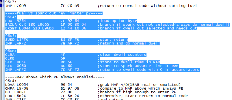
anyways since it came up, what i did for spark cut rev limiting, as an image since formatting the text for a post isn't working as smoothly as i'd like.
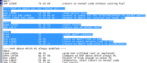
for those unfamiliar with $A1, 005E and 0060 are what are stored to 3FDC and 3FF6 at the end of the dwell calcs. clearing those two words causes the ICM to not trigger the coils, i'm not sure if the coils are held high or don't even begin charging, but it causes no spark to be delivered. i don't do any toggling of the bypass. works on the 2.8/3.1/3.4/3100/3400 DIS units, i ASSUME it would on the dizzy applications as well.
anyways since it came up, what i did for spark cut rev limiting, as an image since formatting the text for a post isn't working as smoothly as i'd like.
for those unfamiliar with $A1, 005E and 0060 are what are stored to 3FDC and 3FF6 at the end of the dwell calcs. clearing those two words causes the ICM to not trigger the coils, i'm not sure if the coils are held high or don't even begin charging, but it causes no spark to be delivered. i don't do any toggling of the bypass. works on the 2.8/3.1/3.4/3100/3400 DIS units, i ASSUME it would on the dizzy applications as well.
Senior Member
Joined: Nov 2006
Posts: 672
Likes: 1
From: Camden, MI
Car: 1985 IROC-Z28
Engine: LB9
Transmission: 700R4
Axle/Gears: 3.73
Re: There's Something Wrong With Your Head
seems to work pretty well, especially for boosted applications looking to build pressure against the first of a 3-step rev limiter compared to a fuel-cut limiter. i still need to stick an ammeter on the ICM's +12V feed to see how it is actually acting when in spark-cut mode.
Thread Starter
Supreme Member
iTrader: (2)
Joined: May 2007
Posts: 2,574
Likes: 0
From: right behind you
Car: '85 maro
Engine: In the works...
Transmission: TH700 R4
Axle/Gears: 3.73 posi
Re: There's Something Wrong With Your Head
This is what I did on PA6E and it works great. Has anyone implemented it into $59 yet?
Member
iTrader: (1)
Joined: Feb 2008
Posts: 463
Likes: 0
From: Connecticut
Car: 1987 Chevrolet Camaro
Engine: 2.8L V6 MPFI
Transmission: 700R4
Axle/Gears: 10 Bolt
Re: There's Something Wrong With Your Head
Car runs, Six_Shooter was right.
The 6th notch or 1&4 firing notch correlates to TDC.
Anyway, how can I tell what kind of adjustments I need? Do I just set the whole timing table to 10* and confirm with light?
The 6th notch or 1&4 firing notch correlates to TDC.
Anyway, how can I tell what kind of adjustments I need? Do I just set the whole timing table to 10* and confirm with light?
Joined: Mar 2006
Posts: 4,370
Likes: 19
Car: 1973 Datsun 240Z/ 1985 S-15 Jimmy
Engine: Turbo LX9/To be decided
Transmission: 5-speed/T-5
Axle/Gears: R200 3.90/7.5" 3.73
Re: There's Something Wrong With Your Head
To check base timing, do it just like you would with a dizzy, disconnect the ESC wire (tan/black) and use a timing light on #1 plug wire. You will get twice as many firing events since it's a waste spark system, but the events are 180* apart and should still be able to see base advance (it's never been an issue for me anyway).
You will need to cycle the ignition after re-connecting to get the ECM to take over advance duties and reset the ESC error that will come up.
You will need to cycle the ignition after re-connecting to get the ECM to take over advance duties and reset the ESC error that will come up.
Thread Starter
Supreme Member
iTrader: (2)
Joined: May 2007
Posts: 2,574
Likes: 0
From: right behind you
Car: '85 maro
Engine: In the works...
Transmission: TH700 R4
Axle/Gears: 3.73 posi
Re: There's Something Wrong With Your Head
Grab a piece of wire (coat hanger works) and use it to indicate where TDC is. Program your table to fire at 0*. Then you can move the tab to adjust it.
Last edited by bl85c; Mar 9, 2014 at 02:45 PM.
Joined: Mar 2006
Posts: 4,370
Likes: 19
Car: 1973 Datsun 240Z/ 1985 S-15 Jimmy
Engine: Turbo LX9/To be decided
Transmission: 5-speed/T-5
Axle/Gears: R200 3.90/7.5" 3.73
Re: There's Something Wrong With Your Head

Why do people want to make this far more difficult than it needs to be?
There's ABSOEFFINGLUTELY ZERO reason to change a single thing in the bin to determine base timing. Once you have the base timing and assuming that the crans sensor is non-adjustable in position there is ONE setting in the bin (not a table) that can be changed to compensate for it, assuming that it is not already matching in the bin.
Moderator
iTrader: (1)
Joined: Mar 2002
Posts: 18,432
Likes: 234
From: Chasing Electrons
Car: check
Engine: check
Transmission: check
Re: There's Something Wrong With Your Head
RBob.
Thread Starter
Supreme Member
iTrader: (2)
Joined: May 2007
Posts: 2,574
Likes: 0
From: right behind you
Car: '85 maro
Engine: In the works...
Transmission: TH700 R4
Axle/Gears: 3.73 posi
Re: There's Something Wrong With Your Head
Why do people want to make this far more difficult than it needs to be?
There's ABSOEFFINGLUTELY ZERO reason to change a single thing in the bin to determine base timing. Once you have the base timing and assuming that the crans sensor is non-adjustable in position there is ONE setting in the bin (not a table) that can be changed to compensate for it, assuming that it is not already matching in the bin.
There's ABSOEFFINGLUTELY ZERO reason to change a single thing in the bin to determine base timing. Once you have the base timing and assuming that the crans sensor is non-adjustable in position there is ONE setting in the bin (not a table) that can be changed to compensate for it, assuming that it is not already matching in the bin.
Last edited by bl85c; Mar 9, 2014 at 02:46 PM.
Joined: Mar 2006
Posts: 4,370
Likes: 19
Car: 1973 Datsun 240Z/ 1985 S-15 Jimmy
Engine: Turbo LX9/To be decided
Transmission: 5-speed/T-5
Axle/Gears: R200 3.90/7.5" 3.73
Re: There's Something Wrong With Your Head
I've stated 3 times already how to measure base timing in this thread alone.
The EXACT same way you would with a dizzy...
When the bypass wire is disconnected, the ECM has ZERO control of timing, just like when a dizzy is used, so that will be base timing. You then use the base timing in the bin for initial advance, exactly like you would in a dizzy application...
Why is this so hard to understand?
Thread Starter
Supreme Member
iTrader: (2)
Joined: May 2007
Posts: 2,574
Likes: 0
From: right behind you
Car: '85 maro
Engine: In the works...
Transmission: TH700 R4
Axle/Gears: 3.73 posi
Re: There's Something Wrong With Your Head
It's probably mostly you.
Get a coat hanger, point it at TDC (or whatever your base is), disconnect the EST -or- program a bin at 0 and measure. Does which way really matter?
Get a coat hanger, point it at TDC (or whatever your base is), disconnect the EST -or- program a bin at 0 and measure. Does which way really matter?
Last edited by bl85c; Mar 10, 2014 at 01:17 PM.
Member
iTrader: (1)
Joined: Feb 2008
Posts: 463
Likes: 0
From: Connecticut
Car: 1987 Chevrolet Camaro
Engine: 2.8L V6 MPFI
Transmission: 700R4
Axle/Gears: 10 Bolt
Re: There's Something Wrong With Your Head
I checked it, the TDC mark is between the 4-8 mark on the tab, with the sync notch between the 12-16 mark.
Shouldn't I just make a mark where the 10* "v" is on the tab somewhere on the engine, then just adjust the bracket until the TDC mark lines up with this mark?