LT1 intake water outlets
 10-30-2015, 02:51 AM
#1
Member

Thread Starter

Join Date: Nov 2005
Location: Edmonton, AB
Posts: 428
Likes: 0
Received 0 Likes
on
0 Posts
Car: '87 Z-28
Engine: LT1-topped 400
Transmission: T56
Axle/Gears: 3.42
LT1 intake water outlets
I'm doing an LT1 intake retrofit onto a 400. I bought the intake from someone who did the modifications to fit a Gen-I smallblock (distributor hole and shim, EGR stuff ground down and blocked, centre mounting holes redrilled, water outlets tapped). Every resource I've seen online has said that the water outlets should be at the front of the manifold so coolant flows backward through the block, up into the heads at the rear, and forward through the heads to the exit, but the fellow drilled and tapped the fittings at the rear of the manifold instead.
Is this okay to adequately cool the engine, or should I punch a couple holes up front for the coolant to exit?
Is this okay to adequately cool the engine, or should I punch a couple holes up front for the coolant to exit?
 11-01-2015, 09:00 AM
#2
Supreme Member
iTrader: (1)

Join Date: Sep 2005
Posts: 26,155
Received 1,694 Likes
on
1,287 Posts
Car: Yes
Engine: Usually
Transmission: Sometimes
Axle/Gears: Behind me somewhere
Re: LT1 intake water outlets
In the 400 block (or any other SBC besides the LT1) the water flows forwards: into the front of the block under some pressure from the pump, around the cyl walls through the water jackets, through abuncha little holes in the head gaskets, through the heads, and out the top somewhere.
The front and the back of the block are absolutely identical the same in every way as far as water flow. Either end will work fine.
About half, maybe a bit more, of the total heat input to the coolant is from the exh ports. Most of the rest, probably 2/3 of the remainder, is through the chamber wall. The remaining tiny fraction is through the cyl walls. Very little heat passes through the block: virtually all of it is lost through the heads. (this of course, not counting what goes into the oil either through the heads or the pistons, and then in some systems passes from the oil into the coolant as well)
The hottest spots in the cooling system are the exh ports. The hottest ones of those, is right at the center, where the 2 are next to each other. The most coolant flow is metered by the head gasket to flow at this point therefore, right under those 2 ports, in the very center of the gasket front-to-rear but almost against the exh side of the head and outside of the block. There's a little group of 3 holes in the gasket at that point. Lay your gaskets on the block, and on the heads, and make sure those 3 holes are unobstructed by any casting material.
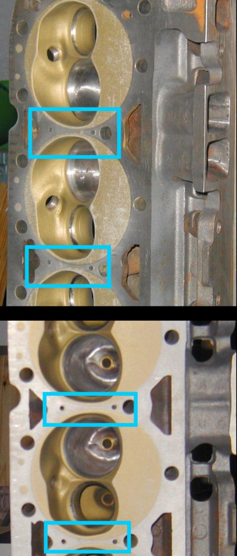
In this pic you can see where I enlarged the hole in question in these heads, looks like it has a round "bump" off to the side of the "slot" the mfr put there.
That said, you're going to have abuncha hoses all running along the valve covers and meeting up at the front to go to the rad. They're gonna pass right immediately above the place the other fitting needs to go, anyway. Might as well go ahead and punch the front ones out too. It works the best to have hot water exh ports at both the front and rear of the motor, with a 1" T fitting at the front. Use �" hose from rear to front, then 1" hose from front to the thermostat housing piece.

This pic of a 400 head gasket shows the cluster of 3 holes that ABSOLUTELY MUST be unobstructed (magenta), as well as the steam holes (cyan); don't forget to drill those in your heads, if they're not already there, with about a 3/16" bit. Drill the ones on the intake side, that are right next to that head bolt, at about a 30 - 45� angle toward the exh side (away from the head bolt), otherwise they will never hit water like they're supposed to. Head bolts are yellow, oil drainback is gray, dowel pins are red. All others are coolant metering.
Note carefully that there is a large hole directly under each of the end exh ports, as well as the group of 3 under the 2 center ones.
You can also see pretty obviously, that the flow at the center of the gasket, is MUCH greater than the flow at the ends. Therefore it doesn't matter which way that bulk of the water has to go, either end is exactly equivalent as far as flow and cooling are concerned.
The front and the back of the block are absolutely identical the same in every way as far as water flow. Either end will work fine.
About half, maybe a bit more, of the total heat input to the coolant is from the exh ports. Most of the rest, probably 2/3 of the remainder, is through the chamber wall. The remaining tiny fraction is through the cyl walls. Very little heat passes through the block: virtually all of it is lost through the heads. (this of course, not counting what goes into the oil either through the heads or the pistons, and then in some systems passes from the oil into the coolant as well)
The hottest spots in the cooling system are the exh ports. The hottest ones of those, is right at the center, where the 2 are next to each other. The most coolant flow is metered by the head gasket to flow at this point therefore, right under those 2 ports, in the very center of the gasket front-to-rear but almost against the exh side of the head and outside of the block. There's a little group of 3 holes in the gasket at that point. Lay your gaskets on the block, and on the heads, and make sure those 3 holes are unobstructed by any casting material.
In this pic you can see where I enlarged the hole in question in these heads, looks like it has a round "bump" off to the side of the "slot" the mfr put there.
That said, you're going to have abuncha hoses all running along the valve covers and meeting up at the front to go to the rad. They're gonna pass right immediately above the place the other fitting needs to go, anyway. Might as well go ahead and punch the front ones out too. It works the best to have hot water exh ports at both the front and rear of the motor, with a 1" T fitting at the front. Use �" hose from rear to front, then 1" hose from front to the thermostat housing piece.
This pic of a 400 head gasket shows the cluster of 3 holes that ABSOLUTELY MUST be unobstructed (magenta), as well as the steam holes (cyan); don't forget to drill those in your heads, if they're not already there, with about a 3/16" bit. Drill the ones on the intake side, that are right next to that head bolt, at about a 30 - 45� angle toward the exh side (away from the head bolt), otherwise they will never hit water like they're supposed to. Head bolts are yellow, oil drainback is gray, dowel pins are red. All others are coolant metering.
Note carefully that there is a large hole directly under each of the end exh ports, as well as the group of 3 under the 2 center ones.
You can also see pretty obviously, that the flow at the center of the gasket, is MUCH greater than the flow at the ends. Therefore it doesn't matter which way that bulk of the water has to go, either end is exactly equivalent as far as flow and cooling are concerned.
Last edited by sofakingdom; 11-01-2015 at 11:48 AM.
11-01-2015, 03:36 PM
#3
Member
Thread Starter
Join Date: Nov 2005
Location: Edmonton, AB
Posts: 428
Likes: 0
Received 0 Likes
on
0 Posts
Car: '87 Z-28
Engine: LT1-topped 400
Transmission: T56
Axle/Gears: 3.42
Re: LT1 intake water outlets
That's some great info, thanks. Engine seemed to be running pretty cool before I pulled it from the donor, but I guess it's no skin off my back to pull the heads and double check for those steam holes; who knows what the P.O. did with it.
The double exits at both ends sounds like a solid plan.
The double exits at both ends sounds like a solid plan.

Thread
Thread Starter
Forum
Replies
Last Post
SixSeriesCSi
Southern California Area
6
08-23-2017 05:12 PM
yellowferrari
History / Originality
16
10-12-2015 11:07 AM