DIY 2-Transistor ALDL Cable Help
 04-03-2010, 11:08 PM
#1
Senior Member

Thread Starter

Join Date: Nov 2006
Location: Camden, MI
Posts: 672
Likes: 0
Received 1 Like
on
1 Post
Car: 1985 IROC-Z28
Engine: LB9
Transmission: 700R4
Axle/Gears: 3.73
DIY 2-Transistor ALDL Cable Help
if possible, i'd like to see some pics(or drawings) of someone's completed and working 2-transistor ALDL cable... i just attempted and from what i can tell, failed at making one. i can find the same diagram roughly 1000 times all over the internet, but very few actual pics/drawings of one and i figured, maybe i'm missing something that other people haven't...
BTW: i chose the 2-transistor circuit since that is what my aldlcable.com one was that eventually quit working after being abused for 2 years... worked great until the end of it's life and all it would do is fail to make or hold a connection. i figured if they can get it working that well(and i did take it apart to confirm), then why can't i?
anyways: i got it all put together, and the only way i can get any of the tests to pass that i've run across (Datamaster being the most useful) is to use jumper wires and connect the TxD and RxD together. my serial-USB adapter(Parallax 28031) lights up it's LED indicating that data is being transfered and it passes the fast test with flying colors. if i remove the jumper wire, FAIL every time... LED doesn't light up either. in another attempt to basically emulate the ALDLcable.com version, i'm drawing +5V from another USB cable to power the serial portion of the circuit. if i don't connect that power cable, then nothing will happen at the convertor. if i do connect it, then i get a VERY brief light-up from the data transmit LED when it first gets connected. i'm not sure what that means to me, but it seems odd...
also, if i take just one end of the jumper wire(the other end being held in my hand) with both USB cable hooked up, and touch the junction where a 10K resistor, the RxD line and the first transistor's collector meet, the red LED lights up... it only does it for a few mS, then goes out, but if i drag the alligator clip along it, it will keep going on and off as the connection breaks and completes... i believe this would also happen if i did it at the junction of a 10K resistor and the first transistor's base, but i'm not very sure of that...
would it help if i posted up a pic/drawing of what i did and maybe someone can point out flaw(s)?
 04-04-2010, 01:24 PM
#2
Senior Member
Thread Starter
Join Date: Nov 2006
Location: Camden, MI
Posts: 672
Likes: 0
Received 1 Like
on
1 Post
Car: 1985 IROC-Z28
Engine: LB9
Transmission: 700R4
Axle/Gears: 3.73
Re: DIY 2-Transistor ALDL Cable Help
slight update...
i was playing with my multi-meter and eventually got around to testing the diode...
when i run the leads normally on the one thats already on the board, i get ~.555V when on the diode test. i figure that's fine since i get roughly the same result with my other 9 that i have sitting around. then i reverse the leads. on the ones that aren't being used, i get nothing, like i expected.
but on the one that's on the board, i got ~.600V... so i thought, "hey maybe the diode is bad", so i desoldered that one out and soldered in a new one that i JUST tested and confirmed as good. now i still get the same result of .55V normal and .60V with the leads reversed...
i'm thinking this may be my issue?
and another thing: from what i just read, transistors are basically pairs of diodes in one package? and i would test them the same way?
04-04-2010, 03:16 PM
#3
Moderator
iTrader: (1)

Join Date: Mar 2002
Location: Chasing Electrons
Posts: 18,405
Likes: 0
Received 216 Likes
on
202 Posts
Car: check
Engine: check
Transmission: check
Re: DIY 2-Transistor ALDL Cable Help
slight update...
i was playing with my multi-meter and eventually got around to testing the diode...
when i run the leads normally on the one thats already on the board, i get ~.555V when on the diode test. i figure that's fine since i get roughly the same result with my other 9 that i have sitting around. then i reverse the leads. on the ones that aren't being used, i get nothing, like i expected.
but on the one that's on the board, i got ~.600V... so i thought, "hey maybe the diode is bad", so i desoldered that one out and soldered in a new one that i JUST tested and confirmed as good. now i still get the same result of .55V normal and .60V with the leads reversed...
i'm thinking this may be my issue?
and another thing: from what i just read, transistors are basically pairs of diodes in one package? and i would test them the same way?
i was playing with my multi-meter and eventually got around to testing the diode...
when i run the leads normally on the one thats already on the board, i get ~.555V when on the diode test. i figure that's fine since i get roughly the same result with my other 9 that i have sitting around. then i reverse the leads. on the ones that aren't being used, i get nothing, like i expected.
but on the one that's on the board, i got ~.600V... so i thought, "hey maybe the diode is bad", so i desoldered that one out and soldered in a new one that i JUST tested and confirmed as good. now i still get the same result of .55V normal and .60V with the leads reversed...
i'm thinking this may be my issue?
and another thing: from what i just read, transistors are basically pairs of diodes in one package? and i would test them the same way?
I searched for a thread that I posted pictures of the 2-transistor that I made. But can't find it. I have also discovered that due the RS-232 spec that the 2-transistor interfaces don't always work. And sometimes work on one laptop but not another.
RBob.
04-04-2010, 03:35 PM
#4
Senior Member
Thread Starter
Join Date: Nov 2006
Location: Camden, MI
Posts: 672
Likes: 0
Received 1 Like
on
1 Post
Car: 1985 IROC-Z28
Engine: LB9
Transmission: 700R4
Axle/Gears: 3.73
Re: DIY 2-Transistor ALDL Cable Help
as far as the 2-trans setup working on some laptops but not others: since the aldlcable.com USB 2-transistor cable worked for me before, is there any reason why wouldn't i be able to get my own to work?
and i will have a way of determining if the USB convertor is somehow causing the problem: my brother is dropping off the old P4 desktop i built that still has a functioning serial port in the back. as soon as i can get to radioshack to pick up another pair of transistors(broke the base off of one while desoldering and the other wasn't looking too great either) anyway.
EDIT: i'm using this diagram and only ever planning on using it with 1227730/1227727 type ECMs, is there anything i should be leaving out/adding because of this?
04-04-2010, 07:06 PM
#5
Moderator
iTrader: (1)
Join Date: Mar 2002
Location: Chasing Electrons
Posts: 18,405
Likes: 0
Received 216 Likes
on
202 Posts
Car: check
Engine: check
Transmission: check
Re: DIY 2-Transistor ALDL Cable Help
Part of the issue with most of the 2-transistor designs is that it doesn't meet RS-232 specs. Note the one you posted. The RxD line is only pulled to ground via Q2. When it should be going negative by at least 3 volts.
In this case it depends upon what the rs-232 converter chip requires (in the USB adapter cable). It may or may not work.
Didn't you mention that the aldlcable USB set up skipped an rs-232 translator chip? With the only chip on the board being the USB controller?
RBob.
In this case it depends upon what the rs-232 converter chip requires (in the USB adapter cable). It may or may not work.
Didn't you mention that the aldlcable USB set up skipped an rs-232 translator chip? With the only chip on the board being the USB controller?
RBob.
04-04-2010, 07:22 PM
#6
Senior Member
Thread Starter
Join Date: Nov 2006
Location: Camden, MI
Posts: 672
Likes: 0
Received 1 Like
on
1 Post
Car: 1985 IROC-Z28
Engine: LB9
Transmission: 700R4
Axle/Gears: 3.73
Re: DIY 2-Transistor ALDL Cable Help
funny how no one mentions this kind of thing until people have issues...
the aldlcable.com USB cable's only IC is the FTDI FT232RL. other than that, there are a few transistors, ~10 resistors, 1 capacitor and that's about it. the Parallax unit i just got has the same FT232RL IC on one side and another IC on the bottom, but i'm not quite sure what it is/it's purpose. i would find it odd if adding more hardware(presumably to make things more likely to work) would cause something to not work...
from what i can read off of it:
ZT213LEEA 0932
89616429.4.T
i know the FTDI "ChiPi" i was looking at before this unit had the FT232RL and another IC, but i believe it was essentially an amplifier? i thought it said it matched TTL levels or something like that. i'm assuming that's what this second IC does as well. google may prove fruitful for me here.
another member had good results with this convertor + 2-transistor setup, which is the basis of why i chose it. i have the serial-port equipped desktop in my posession now, and after a quick trip to radioshack in the morning, i'm rebuilding the ALDL circuit and testing it with a true serial port to rule out either my schematic interpretation and soldering skills or if for some reason, the USB half is wonky.
EDIT: HA! the ChiPi uses the same IC:
For the UC232R(ChiPi) the FT232RL has been used in combination with a Zywyn ZT213LEEA to make a USB to RS232 converter. The Zywyn ZT213LEEA is used to make the TTL to RS232 level conversion and is capable of RS232 communication at up to 250 kilobaud baud.
i'm not sure what all that means though.
Last edited by Saar; 04-04-2010 at 07:26 PM.
04-04-2010, 09:39 PM
#7
Moderator
iTrader: (1)
Join Date: Mar 2002
Location: Chasing Electrons
Posts: 18,405
Likes: 0
Received 216 Likes
on
202 Posts
Car: check
Engine: check
Transmission: check
Re: DIY 2-Transistor ALDL Cable Help
RS-232 voltage levels are a minimum of plus and minus 3 volts. With a maximum of plus and minus 15 volts. Also note that they do not need to be symmetrical. So it can be -4 volts and +9 volts and still be in spec.
USB to Serial adapter: the other chip is a level translator. Using on-board charge pumps along with the capacitors it produces about +8 volts and -8 volts from the 5V supply. The +- 8 volts is used to drive the RS-232 signals.
Note that the RS-232 signals are inverted from the 0-5 V input signals. You can see that in the 2-transistor set up that it inverts the signal. A +5 volts from the ECM translates to -8 volts on the serial side (rs-232).
If you were to build a cable without the level translator, then the transistor side of the circuit would need to be configured to not invert the signal.
Most likely because very few people understand serial communications. I do know that I've mentioned it. But there are so many posts on this topic it is like looking for a needle in a haystack.
My recommendation to people who want a solid serial ALDL cable has been to use a MAX232 type device (as in the USB/serial adapter cables). This way it will work on any laptop/PC with the RS-232 signaling in spec.
RBob.
USB to Serial adapter: the other chip is a level translator. Using on-board charge pumps along with the capacitors it produces about +8 volts and -8 volts from the 5V supply. The +- 8 volts is used to drive the RS-232 signals.
Note that the RS-232 signals are inverted from the 0-5 V input signals. You can see that in the 2-transistor set up that it inverts the signal. A +5 volts from the ECM translates to -8 volts on the serial side (rs-232).
If you were to build a cable without the level translator, then the transistor side of the circuit would need to be configured to not invert the signal.
funny how no one mentions this kind of thing until people have issues...
My recommendation to people who want a solid serial ALDL cable has been to use a MAX232 type device (as in the USB/serial adapter cables). This way it will work on any laptop/PC with the RS-232 signaling in spec.
RBob.
Trending Topics
04-04-2010, 09:49 PM
#8
Senior Member
Thread Starter
Join Date: Nov 2006
Location: Camden, MI
Posts: 672
Likes: 0
Received 1 Like
on
1 Post
Car: 1985 IROC-Z28
Engine: LB9
Transmission: 700R4
Axle/Gears: 3.73
Re: DIY 2-Transistor ALDL Cable Help
RS-232 voltage levels are a minimum of plus and minus 3 volts. With a maximum of plus and minus 15 volts. Also note that they do not need to be symmetrical. So it can be -4 volts and +9 volts and still be in spec.
USB to Serial adapter: the other chip is a level translator. Using on-board charge pumps along with the capacitors it produces about +8 volts and -8 volts from the 5V supply. The +- 8 volts is used to drive the RS-232 signals.
Note that the RS-232 signals are inverted from the 0-5 V input signals. You can see that in the 2-transistor set up that it inverts the signal. A +5 volts from the ECM translates to -8 volts on the serial side (rs-232).
If you were to build a cable without the level translator, then the transistor side of the circuit would need to be configured to not invert the signal.
Most likely because very few people understand serial communications. I do know that I've mentioned it. But there are so many posts on this topic it is like looking for a needle in a haystack.
My recommendation to people who want a solid serial ALDL cable has been to use a MAX232 type device (as in the USB/serial adapter cables). This way it will work on any laptop/PC with the RS-232 signaling in spec.
RBob.
USB to Serial adapter: the other chip is a level translator. Using on-board charge pumps along with the capacitors it produces about +8 volts and -8 volts from the 5V supply. The +- 8 volts is used to drive the RS-232 signals.
Note that the RS-232 signals are inverted from the 0-5 V input signals. You can see that in the 2-transistor set up that it inverts the signal. A +5 volts from the ECM translates to -8 volts on the serial side (rs-232).
If you were to build a cable without the level translator, then the transistor side of the circuit would need to be configured to not invert the signal.
Most likely because very few people understand serial communications. I do know that I've mentioned it. But there are so many posts on this topic it is like looking for a needle in a haystack.
My recommendation to people who want a solid serial ALDL cable has been to use a MAX232 type device (as in the USB/serial adapter cables). This way it will work on any laptop/PC with the RS-232 signaling in spec.
RBob.

so more or less, in theory, the 2-transistor setup will work, but can cause issues depending on the computer that's logging?
if i can't get it working tomorrow with 2 transistors, i'm going to have to go with the MAX232... what was presented as a fairly cheap and easy project has quickly turned into a PITA...
04-05-2010, 08:30 AM
#9
Moderator
iTrader: (1)
Join Date: Mar 2002
Location: Chasing Electrons
Posts: 18,405
Likes: 0
Received 216 Likes
on
202 Posts
Car: check
Engine: check
Transmission: check
Re: DIY 2-Transistor ALDL Cable Help
And neither work with the desktop in the shop. And these are all PC based serial ports, not even going through a USB gizmo.
For the shop PC I ended up with a MC1488 chip and two 9 volt transistor batteries. The MC1488 is the old style level translator that requires +- voltages at the RS-232 levels. I had the chip and by using batteries the circuit was isolated, so I knew that it would work on anything.
This is why the EBL has a MAX232 device on board. From prior knowledge and going through all this I knew beyond a shadow of a doubt that true rs-232 signals are the only way to get reliability. 57.6 kb and solid as a rock.
Which is a problem with USB in a car. Even though the signaling is differential, the voltage levels are low and still prone to noise issues. From what I've seen the noise gets into the USB control chips and sends them for a loop. Then the driver needs to recover and reconnect the USB.
Even if there is top notch filtering at the product end, it doesn't mean the laptop USB hub controller does. And for some stupid reason the laptop makers don't seem to want to include a true serial port on their machines.
RBob.
04-05-2010, 11:34 AM
#10
Supreme Member
iTrader: (1)
Join Date: Apr 2004
Location: Browns Town
Posts: 3,178
Likes: 0
Received 3 Likes
on
3 Posts
Car: 86 Monte SS (730,$8D,G3,AP,4K,S_V4)
Engine: 406 Hyd Roller 236/242
Transmission: 700R4 HomeBrew, 2.4K stall
Axle/Gears: 3:73 Posi, 7.5 Soon to break
Re: DIY 2-Transistor ALDL Cable Help
Since the subject came up...
I built a Max232 setup on my test bench but couldn't get it to work properly. Double checked schematics etc to no avail.
Never got it workingso I figured it was my soldering melted something.
I saw one time a post that one of the capacitors is represented backwards on the schematic but was not able to find the info again to clarify and correct this.
Do you have any insight on that?
http://www.mindspring.com/~amattei/aldlif.jpg
Pic is from AKM Cables, ALDLcables.com
04-05-2010, 11:57 AM
#11
Moderator
iTrader: (1)
Join Date: Mar 2002
Location: Chasing Electrons
Posts: 18,405
Likes: 0
Received 216 Likes
on
202 Posts
Car: check
Engine: check
Transmission: check
Re: DIY 2-Transistor ALDL Cable Help
Since the subject came up...
I built a Max232 setup on my test bench but couldn't get it to work properly. Double checked schematics etc to no avail.
Never got it workingso I figured it was my soldering melted something.
I saw one time a post that one of the capacitors is represented backwards on the schematic but was not able to find the info again to clarify and correct this.
Do you have any insight on that?
http://www.mindspring.com/~amattei/aldlif.jpg
Pic is from AKM Cables, ALDLcables.com
I built a Max232 setup on my test bench but couldn't get it to work properly. Double checked schematics etc to no avail.
Never got it workingso I figured it was my soldering melted something.
I saw one time a post that one of the capacitors is represented backwards on the schematic but was not able to find the info again to clarify and correct this.
Do you have any insight on that?
http://www.mindspring.com/~amattei/aldlif.jpg
Pic is from AKM Cables, ALDLcables.com
It is rather complicated with the 4 transistors as none are really required.
RBob.
04-05-2010, 04:47 PM
#12
Senior Member
Thread Starter
Join Date: Nov 2006
Location: Camden, MI
Posts: 672
Likes: 0
Received 1 Like
on
1 Post
Car: 1985 IROC-Z28
Engine: LB9
Transmission: 700R4
Axle/Gears: 3.73
Re: DIY 2-Transistor ALDL Cable Help
somwhat good news to report:
the tests still all fail miserably.
but on a hunch, i decided to go hook it up and try it anyway.
it works... kinda.
it takes maybe 1/4 second to connect(considering how complex of a connect command i have, that's a good number), then it will display between correct and non-correct data continuously. sometimes TP will pick it up as a checksum error, but most of the time it didn't. i eventually stated moving my whole board around and at one place it displayed data PERFECTLY at a rate of like 8 frames/sec for a good 15 seconds...
so this thing definitely can work, but something is still funny with the circuit... i did test both transistors before hooking them in, both passed with good numbers.
now to figure out WHY it will alternate between a good frame and a bad frame... i MAY need to adjust the port timing settings, but i'm leaning more toward funky soldering since holding it perfectly still in one spot was working(until i moved it and couldn't get it to happen again).
any ideas?
04-05-2010, 05:29 PM
#13
Supreme Member
iTrader: (1)
Join Date: Apr 2004
Location: Browns Town
Posts: 3,178
Likes: 0
Received 3 Likes
on
3 Posts
Car: 86 Monte SS (730,$8D,G3,AP,4K,S_V4)
Engine: 406 Hyd Roller 236/242
Transmission: 700R4 HomeBrew, 2.4K stall
Axle/Gears: 3:73 Posi, 7.5 Soon to break
Re: DIY 2-Transistor ALDL Cable Help
I had this happenning when i first logged with TP V5.
Adding a delay of several mS at the end (or beginning) of the macro may correct it.
I messed with all the port settings then Magnus suggested this and it worked good.
The delay did need to change between different computers if I set it to only 2 mS. a setting of 5-8 mS worked well on all my computers.
Thanks RBob for confirming the diagram too
 04-06-2010, 01:54 PM
#14
Senior Member
Thread Starter
Join Date: Nov 2006
Location: Camden, MI
Posts: 672
Likes: 0
Received 1 Like
on
1 Post
Car: 1985 IROC-Z28
Engine: LB9
Transmission: 700R4
Axle/Gears: 3.73
Re: DIY 2-Transistor ALDL Cable Help
It may be that the command is repeating too quickly.
I had this happenning when i first logged with TP V5.
Adding a delay of several mS at the end (or beginning) of the macro may correct it.
I messed with all the port settings then Magnus suggested this and it worked good.
The delay did need to change between different computers if I set it to only 2 mS. a setting of 5-8 mS worked well on all my computers.
TPV4 doesn't show the erronious data, but it does add to the packet error count(and i only managed a average of 4.4375 correct samples per second, with a target rate of 10 samples per second)...
in 51 seconds, TPV5 recognizes 5 errors with a 50ms timeout, but if i had to estimate, then about half of the samples were junk. with a 100ms timeout; in 49 seconds, TP recognizes 4 errors, though half of all of those samples were junk as well...
i'm not sure what this in indicative of. is it possible i need to add a capacitor or diode somewhere in there to attemp to smooth out something? i ask due to what i found here:
http://www.saturnwiki.net/index.php/ALDL1
i never knew diodes could be used to essentially clean up a signal.
EDIT: maybe my macro skills suck... my connect macro consists of the mode 8 macro 3 times, pause, mode 8, pause, mode 8, pause and then the send data macro.
my monitor macro consists of the mode 1 send, mode 1 reply, then a pause.
but this wouldn't really explain why TPV4 would recognize faults as well...
Last edited by Saar; 04-06-2010 at 01:58 PM.
04-06-2010, 03:01 PM
#15
Senior Member
Thread Starter
Join Date: Nov 2006
Location: Camden, MI
Posts: 672
Likes: 0
Received 1 Like
on
1 Post
Car: 1985 IROC-Z28
Engine: LB9
Transmission: 700R4
Axle/Gears: 3.73
Re: DIY 2-Transistor ALDL Cable Help
more news:
i decided to go see what would happen if i gave the circuit +12V instead of +5V from the USB...
i disconnected the USB plug, used two jumper wires to give it 12V where there was normally 5V and tried to connect... couldn't get any kind of connection to establish.
so i removed the jumpers, plugged the USB Power Only cable back in, and it would connect, although with the same crazy data.
then i decided to bypass the 10K resistor going from +5V cable to the next step in the circuit... now i can't get any kind of response to happen...
i just killed a transistor or two, didn't i?
04-06-2010, 04:35 PM
#16
Senior Member
Thread Starter
Join Date: Nov 2006
Location: Camden, MI
Posts: 672
Likes: 0
Received 1 Like
on
1 Post
Car: 1985 IROC-Z28
Engine: LB9
Transmission: 700R4
Axle/Gears: 3.73
Re: DIY 2-Transistor ALDL Cable Help
well, i'm fairly certain i just junked those transistors...
some success is better than none, but i'm moving onto a 232 circuit if the price is right, i'm done messing with the 2-transistor setup.
since i already have +5V coming from a USB cable, the 78L05 would be unnecessary, correct? i assume a good capacitor would be useful though to smooth out the voltage spikes/dips if there are any.
and from what i can tell, i also wouldn't need to deal with the 160baud line or the mode select line since i don't plan on playing with an ECM that uses either. and if i'm not using the 160Baud T2 In line, i also shouldn't need the T2 out line, right?
after removing all of that, this circuit seems a LOT less complicated than it did...
04-06-2010, 08:24 PM
#17
Senior Member
Thread Starter
Join Date: Nov 2006
Location: Camden, MI
Posts: 672
Likes: 0
Received 1 Like
on
1 Post
Car: 1985 IROC-Z28
Engine: LB9
Transmission: 700R4
Axle/Gears: 3.73
Re: DIY 2-Transistor ALDL Cable Help
it seems i can pick up a pair of MAX232s for $3 shipped... already ordered, now i'll just make my way to radioshack when they get here and finish this...
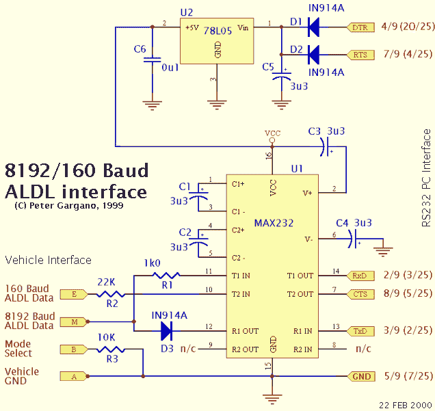
i modified and recreated the diagram from Techedge to come up with what i need. i have to ask: is there enough difference between a 1N914 and a 1N914A diode to make a difference here? i can't find any kind of comparison info on the internet to compare differences, if any...
http://www.robertisaar.co.cc/web_images/max232_aldl.pdf
05-03-2010, 01:54 PM
#18
Senior Member
Thread Starter
Join Date: Nov 2006
Location: Camden, MI
Posts: 672
Likes: 0
Received 1 Like
on
1 Post
Car: 1985 IROC-Z28
Engine: LB9
Transmission: 700R4
Axle/Gears: 3.73
Re: DIY 2-Transistor ALDL Cable Help
after a LOT of time sitting at the post office, my 232s are here. plugged it into a socket i already had wired up and did the TP test. FAIL. went and plugged it into the car, got perfect stream of ALDL data with a 15ms pause between recieveing the previous data packet and sending the command for the next. at 10ms i got at least one bad packet, but it didn't bump up my sampling rate at any kind of significant increase, so i dropped back to 15ms and am enjoying the 8-10 samples a second my 7727 is pushing out.
05-16-2010, 02:29 AM
#19
Supreme Member

Join Date: Aug 1999
Location: sweden
Posts: 2,441
Likes: 0
Received 1 Like
on
1 Post
Car: GTA -89
Engine: Blown 415"
Transmission: 4L80E
Axle/Gears: Strange 12-bolt
Re: DIY 2-Transistor ALDL Cable Help
On my page there are some pictures of how to assembly a 2-trans ALDL cable. I have done alot of them and they work great.
I have also done MAX232 setups and they also work great.
/N.
I have also done MAX232 setups and they also work great.
/N.
05-16-2010, 10:06 AM
#20
Senior Member
Thread Starter
Join Date: Nov 2006
Location: Camden, MI
Posts: 672
Likes: 0
Received 1 Like
on
1 Post
Car: 1985 IROC-Z28
Engine: LB9
Transmission: 700R4
Axle/Gears: 3.73
Re: DIY 2-Transistor ALDL Cable Help
i actually saw your page on it before i started, but i tried building the 2-transistor twice and neither time worked. then i build the MAX232 once and it works perfectly...
10-27-2010, 08:09 PM
#21
Supreme Member
iTrader: (2)

Join Date: May 2009
Location: Delaware
Posts: 3,371
Likes: 0
Received 1 Like
on
1 Post
Car: 91' Firebird SOLD
Engine: 350 TPI +bolt-ons
Transmission: 700r4
Axle/Gears: 3:42
Re: DIY 2-Transistor ALDL Cable Help
i just built the 2 transistor circuit twice man. just wont work,very dissapointed. would you be willing to sell me a max232 style? I will pay you like $25.I would even be happy if you could simplify the max232 circuit for me and i will try to build it myself. Where do these wires go exactly on the circuit board? Please help, i only dream of getting into this car's pcm .
10-30-2010, 09:40 PM
#22
Supreme Member
iTrader: (2)
Join Date: May 2009
Location: Delaware
Posts: 3,371
Likes: 0
Received 1 Like
on
1 Post
Car: 91' Firebird SOLD
Engine: 350 TPI +bolt-ons
Transmission: 700r4
Axle/Gears: 3:42
Re: DIY 2-Transistor ALDL Cable Help
Rob, I cannot get this cable to work to save my life. I built the 2 transistor style schematic from aldl.com. Yes, i used all new and correct part numbers. Checked the schematic that I built over ten times. When using Datamaster , I am now getting this: Your cable is working correctly but the Pcm is not responding. Check cable connections or check for correct version of Datamaster. So, wtf? Is it that sometimes the 2 transistor style cable will not work in some vehicles? I even connected directly to the orange serial data wire on the ecm itself. Still will not work. Ok, I downloaded the aldl cable test from the Moates web site too. Failed all three phases of the test on 2 different pc's. What could be the deal here?
11-08-2010, 11:22 AM
#23
Senior Member
Thread Starter
Join Date: Nov 2006
Location: Camden, MI
Posts: 672
Likes: 0
Received 1 Like
on
1 Post
Car: 1985 IROC-Z28
Engine: LB9
Transmission: 700R4
Axle/Gears: 3.73
Re: DIY 2-Transistor ALDL Cable Help
with the one i made, roughly every other sample was junk, had crazy looking values, but the other samples seemed perfectly correct... so i'm not sure what was up with that. i believe it was suggested that not all laptops like to work outside of true RS232 specs and that causes issues.

Thread
Thread Starter
Forum
Replies
Last Post
Z28/ZR1
Engine/Drivetrain/Suspension Parts for Sale
3
10-23-2015 01:04 PM
TMZIrocZ350
Engine/Drivetrain/Suspension Parts for Sale
1
10-07-2015 12:09 PM