
RFID/Pushbutton Starter Build


Thread Starter
Member
iTrader: (2)
Joined: Apr 2007
Posts: 184
Likes: 1
From: Ashburn, VA
Car: '92 RS
Engine: 305 TBI
RFID/Pushbutton Starter Build
***UPDATE Mar-2011
I'm still working on it. I'm designing all the actual RFID stuff. I also am including a one-touch start function so you don't have to hold the button down while the starter is cranking. you just press it once and the starter will automatically crank until the car starts. I'm also probably gonna include a remote start function since I already have all the radio stuff going. I'd like to hear your guys's input. Let me know what you think would be a good idea to include.
***UPDATE Aug-2010
I got it all working. Here is a video demonstrating almost all the features. I forgot to mention that you can enable the starter, along with any of the selectable ways, with a switch. Either normally open or normally closed. It depends on how you have that option set up on the board. This is handy in case the way the starter is normally enabled fails and so, if you have a hidden backup button, you can still enable it.
_____________________________________________________________________________________________________________________________________________________________
I wanted to have my car start with a simple push/pull of a button. I also wanted to keep VATS intact and be able to use the key if I wanted to. I also wanted to be able to integrate it with my RFID door unlocker. So I decided to do it.
I am probably going to use the switch named Ignition/Start Pull Switch found here http://www.watsons-streetworks.com/i..._switches.html
I wanted to have the toggle and momentary switch combined into one unit so that it would be one single movement to turn the car on. Instead of "flip this switch and press that button." Of course though, if that's what you want, go for it. I will have to modify this switch to make it push instead of pull.
How it works:
The RFID dongle is in my pocket. I walk up to the car. The RFID module in the car reads the dongle and unlocks the doors. It also allows current to flow through the pushbutton and temporarily bypasses the VATS. I get in, put the clutch in, and push the button. My car starts up, and I drive off. I reach my destination and pull the button to turn off the car. I get out and walk away. Once I'm out of range, the RFID module in the car can no longer read the dongle and so locks the doors, cuts current to the pushbutton and returns VATS to normal.
Alternatively, if I don't have the dongle, I can use the key to unlock the doors and turn on the car to drive away like normal.
I should note that all the circuits that receive current when the ignition switch is in the "Run" or "Bulb Test" positions will also receive current when the pushbutton is in the Acc/Run position (pushed in half way). So even without the key or dongle, the accessories can be run.
If someone tries to start the car without a key or the dongle, the car won't start. If they push the button, nothing but the accessories will turn on. The starter will not get power.
I will have to disable the steering column lock, make a circuit board, and splice in a bunch of wires to do this. Luckily, I pretty much have the wiring diagram done. BigBabyLou has already been of great help in this post https://www.thirdgen.org/forums/elec...oid-diode.html, and hopefully the rest of you can help me where I need it.
I have attached my wiring diagram so far. The things that look like -o o- are connection points. Where connectors would go. So basically, the things on the sides (and the pushbutton) are not on the circuit board but somewhere else in the car. The DPST relays that are kind of in the middle are made with the flyback diode already in them, I did not forget to include the diodes.
As I move along with this project, I will update this thread and hopefully document it with pictures once the time comes to put it in my car.
Last edited by �MR.AWESOME!; Feb 28, 2011 at 09:00 PM. Reason: Update
Member
iTrader: (6)
Joined: Oct 2006
Posts: 320
Likes: 0
From: WA
Car: 1989 Camaro Iroc-Z
Engine: 305 TPI (LB9)
Transmission: 700R4
Axle/Gears: 2.77 posi
Re: RFID/Pushbutton Starter Build
Sounds pretty much exactly what I eventually hope to do to my car... Eventually... ") lol...
lol...
On your RFID setup, did you use a kit kind of setup for the core circuitry, or did you do it completely from scratch?
lol...On your RFID setup, did you use a kit kind of setup for the core circuitry, or did you do it completely from scratch?
Thread Starter
Member
iTrader: (2)
Joined: Apr 2007
Posts: 184
Likes: 1
From: Ashburn, VA
Car: '92 RS
Engine: 305 TBI
Re: RFID/Pushbutton Starter Build
I used a kit. It's called K9 Sombra. Ebay has them for under $50. It was the only active RFID kit I could find. It's pretty cheesy and the directions suck, but messing around with a multimeter will tell you all you need to know. It does however work quite well. I haven't had problems with it. If you don't know, there is passive and active RFID. Passive means that the RFID tag has no power source and the reader sends out the signal to get the info from the tag. These usually have a really short range and are useless if you want your doors to unlock while you walk up to your car. Active means that the tag has a power source and it sends out its signal to the reader. Active have a much greater range and the signal can go through non-metallic objects.
Have you worked on any plans for your setup? I would be interested to see if anyone else has thought of a different way to do this.
Have you worked on any plans for your setup? I would be interested to see if anyone else has thought of a different way to do this.
Member
iTrader: (6)
Joined: Oct 2006
Posts: 320
Likes: 0
From: WA
Car: 1989 Camaro Iroc-Z
Engine: 305 TPI (LB9)
Transmission: 700R4
Axle/Gears: 2.77 posi
Re: RFID/Pushbutton Starter Build
No... I haven't even gotten that far with it. I have all these random ideas for cool little electronic things that I want to do to the car, but there's a bunch of other stuff I have to get done to it first. Right now, it's the T-top seals. Which I have been messing with for 6 months or so... I want it to be perfect, but I don't really enjoy body work type stuff, i.e. sanding and painting rusted sealing rails... I just haven't been able to stay motivated...
I'd much rather make electronic thingys, or do engine work, but the electronics are pointless if the car can't really be driven, and engine work (I have a 6.0L GENIII waiting to go in) is really expensive...
The only thing I've actually been consistent on is a little light sequencer project that I want to do a kind of "sequential" 3rd brake light. I've been teaching myself how to program microcontrollers to do it...
EDIT:
That K9 Sombra thing looks pretty cool. I was actually thinking of doing all that from scratch, but why if there's an affordable kit to do the same thing. Thanks for the info.
Last edited by BlueIroc-Z; Mar 29, 2009 at 09:13 PM.
Thread Starter
Member
iTrader: (2)
Joined: Apr 2007
Posts: 184
Likes: 1
From: Ashburn, VA
Car: '92 RS
Engine: 305 TBI
Re: RFID/Pushbutton Starter Build
I was looking for connectors, and have a question. If it is rated at 3A Max, and 250V max, can I run any combination of volts and amps that doesn't exceed 750W? Or do I have to heed each rating separately?
Edit: I looked around and thought some more and I say no. Wire isn't rated for voltage and current. Just current. So the connectors shouldn't take into account voltage either. I don't know if I'm right, though, so please correct me if you know the answer.
Edit: I looked around and thought some more and I say no. Wire isn't rated for voltage and current. Just current. So the connectors shouldn't take into account voltage either. I don't know if I'm right, though, so please correct me if you know the answer.
Last edited by �MR.AWESOME!; Mar 30, 2009 at 10:27 PM.
Member
iTrader: (6)
Joined: Oct 2006
Posts: 320
Likes: 0
From: WA
Car: 1989 Camaro Iroc-Z
Engine: 305 TPI (LB9)
Transmission: 700R4
Axle/Gears: 2.77 posi
Re: RFID/Pushbutton Starter Build
I was looking for connectors, and have a question. If it is rated at 3A Max, and 250V max, can I run any combination of volts and amps that doesn't exceed 750W? Or do I have to heed each rating separately?
Edit: I looked around and thought some more and I say no. Wire isn't rated for voltage and current. Just current. So the connectors shouldn't take into account voltage either. I don't know if I'm right, though, so please correct me if you know the answer.
Edit: I looked around and thought some more and I say no. Wire isn't rated for voltage and current. Just current. So the connectors shouldn't take into account voltage either. I don't know if I'm right, though, so please correct me if you know the answer.
Trending Topics
Thread Starter
Member
iTrader: (2)
Joined: Apr 2007
Posts: 184
Likes: 1
From: Ashburn, VA
Car: '92 RS
Engine: 305 TBI
Re: RFID/Pushbutton Starter Build
That brake light idea is freakin' cool.
I found a cheaper way to do what I want without having to know the connector current issue. But thanks though. One of the guys on the thread said no, my common sense says yes. Who knows. I'm just in the process of picking out the connectors and then I will order the parts, hook them together with a breadboard or something and test it all out. If it all works perfectly, then I will get a PCB made, make it look pretty and be done with it.
I found a cheaper way to do what I want without having to know the connector current issue. But thanks though. One of the guys on the thread said no, my common sense says yes. Who knows. I'm just in the process of picking out the connectors and then I will order the parts, hook them together with a breadboard or something and test it all out. If it all works perfectly, then I will get a PCB made, make it look pretty and be done with it.
Member
iTrader: (6)
Joined: Oct 2006
Posts: 320
Likes: 0
From: WA
Car: 1989 Camaro Iroc-Z
Engine: 305 TPI (LB9)
Transmission: 700R4
Axle/Gears: 2.77 posi
Re: RFID/Pushbutton Starter Build
Are you talking about a full on custom CNC'd board, like where you design it with some software, send it to the company and they print out the boards for you all professional like. Or just a Radio Shack prototype board? I ask because I have looked around at the custom boards and they are really expensive. I was just wondering if you had maybe found a cheaper source...?
Thread Starter
Member
iTrader: (2)
Joined: Apr 2007
Posts: 184
Likes: 1
From: Ashburn, VA
Car: '92 RS
Engine: 305 TBI
Re: RFID/Pushbutton Starter Build
Yep. Custom. Pad2Pad is the company/software. It is really easy to use. I found out about them from emachineshop which is a simple cad program and then you send the file to them and they make it and send it to you. The two companies are related. Check 'em out, yo.
Edit: Well, at least i think it's cheap. I don't know what your definition of expensive is. A rough draft 4x4 inch board that I made on there cost $70. But I can get 2 or 3 for the same total price. The price only increases every 3 boards. So $25 isn't bad. The new design I have planned will be smaller, though, so the price should be lower.
Edit: Well, at least i think it's cheap. I don't know what your definition of expensive is. A rough draft 4x4 inch board that I made on there cost $70. But I can get 2 or 3 for the same total price. The price only increases every 3 boards. So $25 isn't bad. The new design I have planned will be smaller, though, so the price should be lower.
Last edited by �MR.AWESOME!; Mar 31, 2009 at 11:57 PM.
Member
iTrader: (6)
Joined: Oct 2006
Posts: 320
Likes: 0
From: WA
Car: 1989 Camaro Iroc-Z
Engine: 305 TPI (LB9)
Transmission: 700R4
Axle/Gears: 2.77 posi
Re: RFID/Pushbutton Starter Build
Well, I am pretty cheap... But, yeah that Pad2Pad is significantly cheaper than I remember some of the other places being. Seems like they cater more to individual hobbyist kinds of people not big companies with huge production runs...
I kind of wanted to see if I could get some MemCal chip adapter things made, so I could keep one and sell the others for cheaper than the competition, but still make up the cost of having them made. Looks like Pad2Pad will be where I go for that when the time comes.
EDIT:
Hey, funny how stuff works sometimes. Talking about the brake thing again got me motivated to get a program written for the microcontroller. All it took was a little re-reading of datasheet and I think I finally got it. The software simulator shows it working just right... Now all I gotta do is figure out what all I want to do for external components and get an order put in at Mouser and I'll be on my way.
But, yeah that Pad2Pad is significantly cheaper than I remember some of the other places being. Seems like they cater more to individual hobbyist kinds of people not big companies with huge production runs...I kind of wanted to see if I could get some MemCal chip adapter things made, so I could keep one and sell the others for cheaper than the competition, but still make up the cost of having them made. Looks like Pad2Pad will be where I go for that when the time comes.
EDIT:
Hey, funny how stuff works sometimes. Talking about the brake thing again got me motivated to get a program written for the microcontroller. All it took was a little re-reading of datasheet and I think I finally got it. The software simulator shows it working just right... Now all I gotta do is figure out what all I want to do for external components and get an order put in at Mouser and I'll be on my way.
Last edited by BlueIroc-Z; Apr 1, 2009 at 03:28 AM.
Member
iTrader: (2)
Joined: Mar 2009
Posts: 340
Likes: 0
From: Evansville, IN
Car: I have a 91 Camaro RS
Engine: 383 stroker
Transmission: Stock automatic 700r4
Axle/Gears: I have 3.73 Gears with a Eaton posi
Re: RFID/Pushbutton Starter Build
Awsome, project Keep us posted on the progress.
Banned
iTrader: (12)
Joined: Jul 1999
Posts: 12,212
Likes: 13
From: Bertram (outside Austin), TX
Car: 87 GTA
Engine: L98
Transmission: 700R4
Axle/Gears: Dana M78 3.27 posi
Re: RFID/Pushbutton Starter Build
STS Hazards
Thread Starter
Member
iTrader: (2)
Joined: Apr 2007
Posts: 184
Likes: 1
From: Ashburn, VA
Car: '92 RS
Engine: 305 TBI
Re: RFID/Pushbutton Starter Build
So, once again, I have decided to make one of my projects harder. With all this talk of microcontrollers, I decided to use one. I'm hoping to give this project the flexibility to be used with different set ups, keep all the same features I currently have planned, and make it easier to use.
So far, I want it to be enabled (allow the button to actually do something) in one of three different ways.
1) With a 12V source
2) With a momentary switch
3) With a toggle switch
4) Permanently enabled so that it will always work
I also want three different button set-ups possible.
1) A single momentary switch
2) One momentary and one toggle switch
3) Two momentary switches
I think this is all possible and relatively easy to do. The coming days of lernen will reveal if that is so.
Member
iTrader: (6)
Joined: Oct 2006
Posts: 320
Likes: 0
From: WA
Car: 1989 Camaro Iroc-Z
Engine: 305 TPI (LB9)
Transmission: 700R4
Axle/Gears: 2.77 posi
Re: RFID/Pushbutton Starter Build
That would basically be like how the hazards work with a STS unit installed, except all the bulbs turn off together & just turn on sequentially.
STS Hazards
STS Hazards
. Did you ever make a thread detailing how you make your STS unit (microcontroller programs, circuit diagrams, etc.)? I mean, I fully understand if that is proprietary and what not, given you are selling them...So, once again, I have decided to make one of my projects harder. With all this talk of microcontrollers, I decided to use one. I'm hoping to give this project the flexibility to be used with different set ups, keep all the same features I currently have planned, and make it easier to use.
That's what happened to me, I was all like I'll do it the easy way with a schematic I found on the internet with like 3 different IC's that cost like 4 dollars + external components. Then, I found out about micros, and it was like why pay $4 and have a bunch of IC's hanging around, when you can have a fully programmable option for only like $.75 (not including the investment in a programmer ~$10).The part that took forever was figuring out the programming nuances, like what all has to be setup which way in order for everything else to work the way you need it to. Anyway, if you need any help with that end of it, give me a shout. I'm by no means an expert (19yrs old with no electronic engineering background, just a self taught hobbyist), but having been through it once, I might be able to help with the little things that had given me problems.
So good luck. And, I must apologize as I kind of feel like I stole your thread a little with my whole brake light thing...
Thread Starter
Member
iTrader: (2)
Joined: Apr 2007
Posts: 184
Likes: 1
From: Ashburn, VA
Car: '92 RS
Engine: 305 TBI
Re: RFID/Pushbutton Starter Build
No don't worry about stealing it, hasn't been full on hijacked. Haha. Yea I'm only a 20 year old community college student. Skool has never really taught me much. TV and myself do most of my education. I started to teach myself some C++ awhile back and am taking Java in skool now, so I feel confident that I can program it. If I get stuck, though, I'll definitely call upon your help.
What are you using for a compiler? And what microcontroller are you gonna use?
What are you using for a compiler? And what microcontroller are you gonna use?
Last edited by �MR.AWESOME!; Apr 1, 2009 at 11:48 PM.

Member
Joined: Jan 2009
Posts: 134
Likes: 0
From: St. Aug
Car: 92 Z03 RS TBI
Engine: 5.0 L03
Transmission: T-5
Re: RFID/Pushbutton Starter Build
wow looks like it'd make a good cheap alarm setup. I'm tempted to get it. Looks sweet.
And That sounds awesome. You should sell a kit when you finish it :P
And That sounds awesome. You should sell a kit when you finish it :P
Member
iTrader: (6)
Joined: Oct 2006
Posts: 320
Likes: 0
From: WA
Car: 1989 Camaro Iroc-Z
Engine: 305 TPI (LB9)
Transmission: 700R4
Axle/Gears: 2.77 posi
Re: RFID/Pushbutton Starter Build
No don't worry about stealing it, hasn't been full on hijacked. Haha. Yea I'm only a 20 year old community college student. Skool has never really taught me much. TV and myself do most of my education. I started to teach myself some C++ awhile back and am taking Java in skool now, so I feel confident that I can program it. If I get stuck, though, I'll definitely call upon your help.
What are you using for a compiler? And what microcontroller are you gonna use?
What are you using for a compiler? And what microcontroller are you gonna use?

For the micros, I do the programming in assembly language, using Microchip's own free software, MPLAB IDE. I have virtually no experience with higher level programming languages (tiny bit of BASIC, but that's it and that was unrelated to micros). So, for that reason assembly was easy enough to learn. Got a pretty darn good start from this tutorial, regarding assembly language and Microchip's microcontrollers.
As for the microcontroller itself, I had started on a PIC12F629 which comes in an 8 pin DIP package and has 5 I/O pins + 1 input only. Then I realized that I could do just fine with the PIC10F200 (their cheapest option), which is also an 8 pin DIP (2 pins are not used), but has only 3 I/O + 1 input only. The 10F200 is only like $0.64 @ Mouser.
Anyway, Microchip has a very large selection of all kinds of micros, bunch of different combinations of features and stuff.
Yeah, that kit seems like a damn good deal for what all it does...
Thread Starter
Member
iTrader: (2)
Joined: Apr 2007
Posts: 184
Likes: 1
From: Ashburn, VA
Car: '92 RS
Engine: 305 TBI
Re: RFID/Pushbutton Starter Build
I got almost all the code written. I just have to learn how to add in some debounce delays. Once I get the programmer, I will test it out and get any bugs out. Then I'll buy all the other parts and do a "dress rehearsal", as I am calling it. Once I get that working perfectly, I will get the PCB made.
I kind of wanna sell this. I don't know if there would be any interest, though. Let me know what you think.
I'm not sure if I have the circuits around the PIC correct. If it looks messed up or just wrong, please tell how to fix it.
I kind of wanna sell this. I don't know if there would be any interest, though. Let me know what you think.
I'm not sure if I have the circuits around the PIC correct. If it looks messed up or just wrong, please tell how to fix it.
Last edited by �MR.AWESOME!; Apr 17, 2010 at 08:51 PM. Reason: updated diagram
Member
iTrader: (6)
Joined: Oct 2006
Posts: 320
Likes: 0
From: WA
Car: 1989 Camaro Iroc-Z
Engine: 305 TPI (LB9)
Transmission: 700R4
Axle/Gears: 2.77 posi
Re: RFID/Pushbutton Starter Build
Anyway, first thing is GP5. No matter what that input will always read as 1, given it is tied directly to Vdd.
Second, is GP1. As I remember, the PIC can only sink or source like 20mA, I am not sure that that is enough to activate a relay (Aux-Run/Bulb). Also, it is 5 volts, so you might want to check how that would work with the relay too.
Third, GP0. I'm not sure of the purpose of the "Start Relay." It appears to only be there to allow the signal from GP0 to pass to the Aux-Run/Start relay under certain conditions. But, the PIC doesn't supply enough current to warrant the use of a relay. Other than that, the same issue with GP1 applies.
That's all I got for now. Because I'm not totally acquainted with all aspects of your design, you might have reasons for some of that stuff that I don't know... But, I definitely welcome any explanation.
EDIT: Is one of your relays called the "Mom Enable" relay?
 j/k, just made me laugh a little...
 Thread Starter
Member
iTrader: (2)
Joined: Apr 2007
Posts: 184
Likes: 1
From: Ashburn, VA
Car: '92 RS
Engine: 305 TBI
Re: RFID/Pushbutton Starter Build
Haha. Yeah. It's the Momentary Enable Switch. The software I use doesn't allow long labels. So I get creative and unclear.
The DPST relays that are driven by the pic are 5V and somewhere under 25mA, so no worries there.
Where did you hear that GP5 is always read as high? I can't find anything in the datasheet about it. I'm using the 12F508, if that makes any difference.
Did I do the voltage regulator right? I was iffy about that.
Last edited by �MR.AWESOME!; Apr 5, 2009 at 10:22 PM.
Member
iTrader: (6)
Joined: Oct 2006
Posts: 320
Likes: 0
From: WA
Car: 1989 Camaro Iroc-Z
Engine: 305 TPI (LB9)
Transmission: 700R4
Axle/Gears: 2.77 posi
Re: RFID/Pushbutton Starter Build
GP5 will always read high due to the way it is wired in the schem. It is tied directly to the +5 supply. (Maybe you meant to have it tied in on the other side of DIP (5)...?)
As for the v. reg., yeah that looks right, same as the example they show in the datasheet.
As for the v. reg., yeah that looks right, same as the example they show in the datasheet.
Last edited by BlueIroc-Z; Apr 5, 2009 at 11:10 PM.
Thread Starter
Member
iTrader: (2)
Joined: Apr 2007
Posts: 184
Likes: 1
From: Ashburn, VA
Car: '92 RS
Engine: 305 TBI
Re: RFID/Pushbutton Starter Build
Ohhh. Now I see. Good eyes. This is why I have people look over this stuff. Dip 4 would also not work the way I wanted with it wired like that. It's all fixed now, though.
I updated the design on the post with the second diagram. The one I just posted.
I updated the design on the post with the second diagram. The one I just posted.
Last edited by �MR.AWESOME!; Apr 5, 2009 at 11:36 PM.
Thread Starter
Member
iTrader: (2)
Joined: Apr 2007
Posts: 184
Likes: 1
From: Ashburn, VA
Car: '92 RS
Engine: 305 TBI
Re: RFID/Pushbutton Starter Build
A little update.
I wrote the code, bought most of the parts, and then thought that I needed a PIC with 8 I/O pins instead of the 10 I bought with only 6 I/O pins. The reason for that being I was thinking the VATS constantly reads the resistance while driving, and If the RFID were to lose signal while driving down the road, the car would shut off. Not good. So I needed to come up with a different way which involved more I/O pins. However, I asked in a separate thread whether the VATS is always looking for the right value and got mixed answers. So I don't yet know the true answer. It doesn't matter, though, as my new design is more robust and will be able to handle any 12V input better this way.
The circuit board is looking like it's going to be 1.75" by 3". Nice and small. The 40A relays will be external from the board so they don't take up ridiculous amounts of room and to get rid of any possibly harmful noise from them.
I was curious to see if anyone else sells pushbutton kits so I looked around the nets and webs of the inter-kind. The only decent one I could find that incorporates both RFID and pushbutton is going for $400!. That is straight wack. And the price wasn't even listed on the site. I had to search the name of it and found someone saying they emailed him and they weren't yet for sale but when they come out, yadda yadda yadda. It doesn't give you options, either. You have to use their setup. Here is the link if y'all are interested.
http://www.auto-hub.com/stardrive_pu..._ignition.html
But of course, I'm going to think my design is better.
The only thing is that it truly is in this case. haha.
I'll post another update when shtuff happens, aight?
Member
Joined: Jan 2009
Posts: 134
Likes: 0
From: St. Aug
Car: 92 Z03 RS TBI
Engine: 5.0 L03
Transmission: T-5
Re: RFID/Pushbutton Starter Build
well when you figure it out, you should market it to us as an addon to the k9 system 
I mean, you could always just bypass the vats, but that's not optimal for normal use... or safety.
I mean, you could always just bypass the vats, but that's not optimal for normal use... or safety.
Thread Starter
Member
iTrader: (2)
Joined: Apr 2007
Posts: 184
Likes: 1
From: Ashburn, VA
Car: '92 RS
Engine: 305 TBI
Re: RFID/Pushbutton Starter Build
Yeah. I do want to sell them. The way I have it set up now gives you a lot of options. You can have an external 12V source (ex: K9 RFID), a momentary switch, or a toggle switch to activate the VATS. You could also just jump the toggle switch pins and have VATS permanently disabled. And then on the other side of it, three start/acc button setups. A single pushbutton to turn on the accessories and to turn on the car. Two pushbuttons; one for accessories and one for starting. And lastly, a toggle and a pushbutton. The toggle for accessories and a pushbutton for starting.
The single pushbutton setup works likes this. You push it and the accessories come on. If you keep holding it, the starter comes on and once you let go, the starter turns off and your car stays on. You press it again and your car turns off.
If you don't want to turn the car on and just want to have the accessories running, you just push the button and let go before about .5 seconds. Press again to turn off the accessories. Or you can press and hold for longer than .5 seconds and the starter will come on and start the car.
The toggle and double pushbutton setups work pretty much as you imagine. Press/toggle the accessory one and then press the starter one. Turn off by pressing/toggling the accessory one.
How much do you think this is worth? How much would you guys want to pay (if at all) for this?
Thread Starter
Member
iTrader: (2)
Joined: Apr 2007
Posts: 184
Likes: 1
From: Ashburn, VA
Car: '92 RS
Engine: 305 TBI
Re: RFID/Pushbutton Starter Build
I got all the bugs worked out of the code today and it works perfectly in the test circuit. I just have to order the PCB's, make the box, put it all together and wire it in the car. I am positive it will work as planned.
If 1 or 2 people would like one of these first ones with no guarantee of it working in your car, pm me. I will only charge cost of materials and shipping to you.
Oh yea. I shrunk the PCB down to 1.5" x 2.75". The box will probably make it 2" x 3", though.
If 1 or 2 people would like one of these first ones with no guarantee of it working in your car, pm me. I will only charge cost of materials and shipping to you.
Oh yea. I shrunk the PCB down to 1.5" x 2.75". The box will probably make it 2" x 3", though.
Last edited by �MR.AWESOME!; Apr 25, 2009 at 06:39 PM.
Thread Starter
Member
iTrader: (2)
Joined: Apr 2007
Posts: 184
Likes: 1
From: Ashburn, VA
Car: '92 RS
Engine: 305 TBI
Re: RFID/Pushbutton Starter Build
So a month later and I got the circuit boards. Come this weekend I will wire it up in the car and test it out. Still haven't picked out my pushbutton yet so I will probably just use whatever I have laying around for a bit.
And my car which I finally got back form paint.

And my car which I finally got back form paint.

Last edited by �MR.AWESOME!; Apr 17, 2010 at 08:47 PM.

Junior Member
Joined: Mar 2009
Posts: 22
Likes: 0
Re: RFID/Pushbutton Starter Build
So, once again, I have decided to make one of my projects harder. With all this talk of microcontrollers, I decided to use one. I'm hoping to give this project the flexibility to be used with different set ups, keep all the same features I currently have planned, and make it easier to use.
So far, I want it to be enabled (allow the button to actually do something) in one of three different ways.
1) With a 12V source
2) With a momentary switch
3) With a toggle switch
4) Permanently enabled so that it will always work
I also want three different button set-ups possible.
1) A single momentary switch
2) One momentary and one toggle switch
3) Two momentary switches
I think this is all possible and relatively easy to do. The coming days of lernen will reveal if that is so.
So far, I want it to be enabled (allow the button to actually do something) in one of three different ways.
1) With a 12V source
2) With a momentary switch
3) With a toggle switch
4) Permanently enabled so that it will always work
I also want three different button set-ups possible.
1) A single momentary switch
2) One momentary and one toggle switch
3) Two momentary switches
I think this is all possible and relatively easy to do. The coming days of lernen will reveal if that is so.
Thread Starter
Member
iTrader: (2)
Joined: Apr 2007
Posts: 184
Likes: 1
From: Ashburn, VA
Car: '92 RS
Engine: 305 TBI
Re: RFID/Pushbutton Starter Build
Yo. Sorry for the super-late reply. I didn't get an email telling me someone had posted here. That seems a bit too complex for me. If you get everything else figured out but want help with the starting system, I'd be glad to help. Sorry I can't help with that.
Thread Starter
Member
iTrader: (2)
Joined: Apr 2007
Posts: 184
Likes: 1
From: Ashburn, VA
Car: '92 RS
Engine: 305 TBI
Re: RFID/Pushbutton Starter Build
So almost a year later and I'm finally working on this again. The latching relay wasn't working how it was supposed to and that pissed me off so I left the project to come back to when I wasn't pissed off. Then I never really got back around to it. But today I picked it back up and figured out why the damn thing wasn't working. I had assumed that one pulse of current would energize the coil and flip the relay and that another pulse would flip it back. You know what assuming does...
What I found out was that one pulse flips the relay like you would expect. in order to flip it back, however, the second pulse needs to have the direction of the current be opposite of the first pulse. So, positive to negative and negative to positive. This is really annoying. So I got two options here, Find a relay that has the same footprint as the relay I'm using but works the way I want it to, or use an external circuit to flip the direction of the current after every pulse. I will let you know what goes down.
What I found out was that one pulse flips the relay like you would expect. in order to flip it back, however, the second pulse needs to have the direction of the current be opposite of the first pulse. So, positive to negative and negative to positive. This is really annoying. So I got two options here, Find a relay that has the same footprint as the relay I'm using but works the way I want it to, or use an external circuit to flip the direction of the current after every pulse. I will let you know what goes down.
Member
Joined: Nov 2000
Posts: 283
Likes: 0
From: Plainwell, Mi U.S.A.
Car: 89 firebird, 03 Avalanche z71
Engine: 5.0 stock (for now)
Transmission: 700R4 auto
Axle/Gears: stock 2.73 for now
Re: RFID/Pushbutton Starter Build
yes please let us know, I am very interested in this design of yours.
Thread Starter
Member
iTrader: (2)
Joined: Apr 2007
Posts: 184
Likes: 1
From: Ashburn, VA
Car: '92 RS
Engine: 305 TBI
Re: RFID/Pushbutton Starter Build
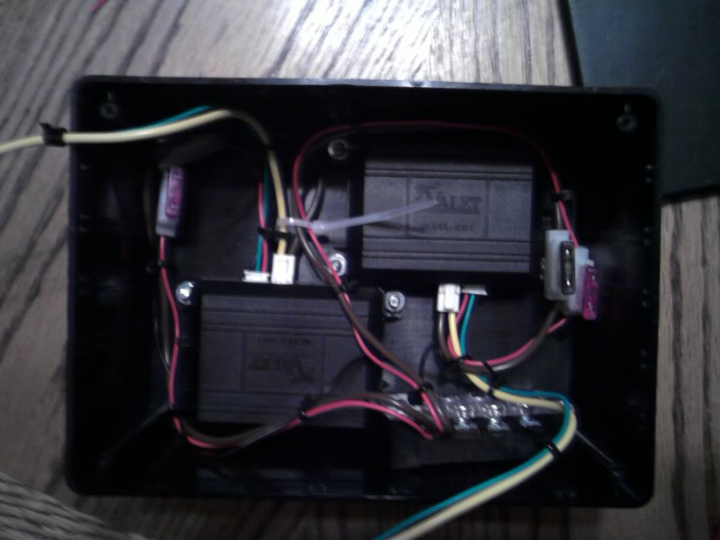
So I am going to use a DPDT relay to fix this pesky problem. The two SPST relays on the left are inside of the K9 Sombra. They close to either lock or unlock the doors. Their contacts connect to the wires that come off of the lock/unlock buttons and imitate someone pressing the physical button. This DPDT relay solution does the exact same thing that the door lock relay assembly does. In fact, that's where I got the idea. Crazy, huh? This is not an ideal solution for me, but it should work. I will figure out a better, neater solution...eventually.
Thread Starter
Member
iTrader: (2)
Joined: Apr 2007
Posts: 184
Likes: 1
From: Ashburn, VA
Car: '92 RS
Engine: 305 TBI
Re: RFID/Pushbutton Starter Build
The better, neater solution has arrived! Another two months of work have paid off. I have updated pretty much the whole design on top of figuring out the original latching relay problem. The circuit board is smaller, there are a few more options included, everything is more robust and the whole thing is cheaper. I'm just going to look over everything a few more times before I order the parts. I'm excited.
Junior Member
Joined: Apr 2004
Posts: 37
Likes: 0
From: Tomball Tx.
Car: 90 GTA, 72 Chevelle, 76 GrandPrix
Engine: 350TPI, 383, 400
Transmission: 700r4, Th350, Th400
Re: RFID/Pushbutton Starter Build
Hey guys I built This RFID push button start for my 72 chevelle back in January using the K-9 Sombra and solid state circuit I have one momentary switch that does every thing.
First press = ACC
Second press = IGN & ACC
Third press with out Brake = OFF
Third press with Brake = START
Fourth Press = ALL OFF
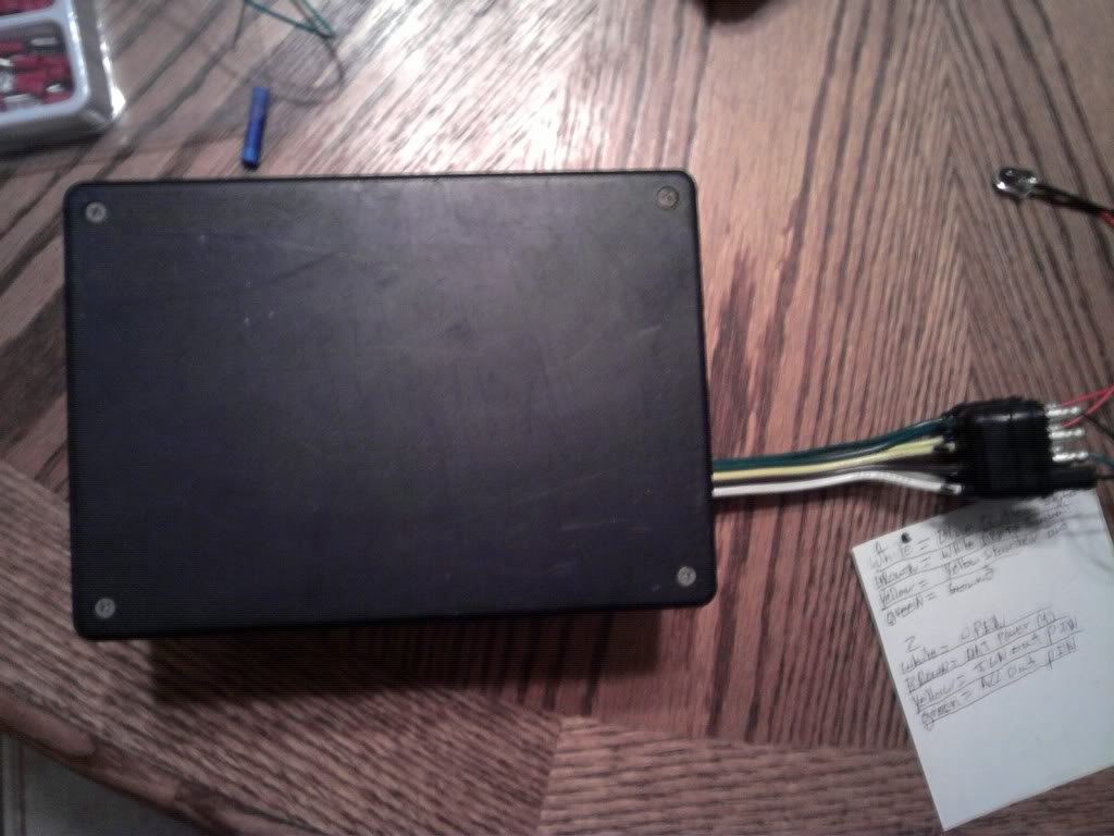
CONTROL BOX
Heres a VIDEO
http://www.youtube.com/watch?v=n0iypBQiA6A
If you have any questions just ask.
First press = ACC
Second press = IGN & ACC
Third press with out Brake = OFF
Third press with Brake = START
Fourth Press = ALL OFF
CONTROL BOX
Heres a VIDEO
http://www.youtube.com/watch?v=n0iypBQiA6A
If you have any questions just ask.
Thread Starter
Member
iTrader: (2)
Joined: Apr 2007
Posts: 184
Likes: 1
From: Ashburn, VA
Car: '92 RS
Engine: 305 TBI
Re: RFID/Pushbutton Starter Build
That's pretty cool. I would love to know the details, but not in this thread. Start your own to tell us about it.

Joined: Sep 2002
Posts: 3,685
Likes: 10
From: PA
Car: 86 Trans AM
Engine: LS1 (not stock...)
Transmission: Built T56
Axle/Gears: Strange 12-bolt w/ 3.73
Re: RFID/Pushbutton Starter Build
Im all in for this... I cant believe I didnt see this thread until now. Im all about tech gadgets. And the thought that I could set my car up to work like a newer car with keyless ignition, while still retaining security, makes me happy.
Pontiac400's video is sweet. Thats about how Ide like my stuff to work. As long as its nearly impossible for anyone else to get in and start the car, Ide be down. I also like the RFID kit so the doors lock/unlock when you approach the car. I dont have power locks...but I have all the parts to add them. So adding them, and instlaling the kit at the same time would be a real piece of cake. I could build a custom harness...which I have to do anyway...and incorporate the new wiring.
Hopefully mrawesome finishes his project, because his sounds really cool! Programming is WAY beyond me. I wouldnt mind learning, but if someone else builds what I need, I also wouldnt mind just paying for it haha.
J.
Thread Starter
Member
iTrader: (2)
Joined: Apr 2007
Posts: 184
Likes: 1
From: Ashburn, VA
Car: '92 RS
Engine: 305 TBI
Re: RFID/Pushbutton Starter Build
Glad to hear it! I'm working on the PCB layout right now and should be done with it this weekend. The boards will take about 2 weeks to get here and then I'll put everything together. I also have to write out the directions, but I'll do that while the boards are being made. I'm gonna write up an updated feature list in a li'l bit, too.
Thread Starter
Member
iTrader: (2)
Joined: Apr 2007
Posts: 184
Likes: 1
From: Ashburn, VA
Car: '92 RS
Engine: 305 TBI
Re: RFID/Pushbutton Starter Build
�Updated Feature List!
Ways To Enable:
1) Normally on or normally off 12V momentary or toggle source. ("Normally" meaning the state that it is in when not "Enabled.")
2)Normally open (N/O) or normally closed (N/C) momentary switch.
3)N/O or N/C toggle switch.
Ways To Start The Car And/Or Turn On The Accessories:
1)Single push-button (Push for less than 0.5s for accessories, more than 0.5s to start)
2)Two push-buttons
3)One push-button and one toggle switch
The P-Button can also be set so that whatever button/toggle switch is used for the accessories (or the button used for both ACC and starter in the case of a single push-button setup) will work even when the P-Button is not "Enabled."
Example: I don't have my RFID dongle (which, when in range, "Enables" the P-Button) or my keys with me, but I want to get a CD out of the head unit. I press the button and the accessories come on. I get the CD and press the button again to turn off the accessories.
Interface With Other Devices:
When the P-Button is "Enabled," the VATS is activated along with two other relays.
One N/C or N/O 12V Source: There are three connections; N/O +12V, N/C +12V and Ground.
One N/C or N/O SPDT Relay: There are your typical SPDT relay connections; N/O, N/C and Common.
Relay Drivers:
There are three separate outputs for the relays that splice in to the under-dash wires. Start, Run and ACC.
The VATS still works how it's supposed to. it isn't any easier to bypass it.
You can still use your keys as you normally would. The only thing you have to do to use the P-Button is disable the steering lock.

Member
iTrader: (1)
Joined: Nov 2008
Posts: 109
Likes: 0
From: Lynchburg, VA
Car: 92 RS
Engine: 305 TBI
Transmission: T-5
Axle/Gears: 4th Gen/3.23/Posi
Re: RFID/Pushbutton Starter Build
I'm interested, fo sho. When I came across this thread and started reading it over, I was afraid it would be dead by now. Glad to see it's still rolling
Thread Starter
Member
iTrader: (2)
Joined: Apr 2007
Posts: 184
Likes: 1
From: Ashburn, VA
Car: '92 RS
Engine: 305 TBI
Re: RFID/Pushbutton Starter Build
So I ordered everything. It'll be another week or two before I have a board all ready to go.
I have one question for y'all. The way I have it set up right now, when the "accessories" are on, I really mean the equivalent state of the key is "Run." When you flip the "ACC" switch, you are really putting it into "Run." I never use the ACC position in my car. I only flip it to Run. That's why set it up like this. Would you guys (and possibly gals) want to have the "ACC" switch turn on the accessories or the "Run" stuff?
I could also just have two different versions of code and load which ever one you would want. I'm a wee bit pissed that I didn't think of this earlier. Oh well, I'll include that option in the next batch of PCB's I get made.
Thread Starter
Member
iTrader: (2)
Joined: Apr 2007
Posts: 184
Likes: 1
From: Ashburn, VA
Car: '92 RS
Engine: 305 TBI
Re: RFID/Pushbutton Starter Build
Oooookay. Soooo, yep. Who wants one? I've been working my *** off on perfecting this thang. Just thought I'd poll the masses. I'm working on making a demo circuit so I can take a video demonstrating all the features, and to prove that I actually have something that works. But yea, who would care to say they want one? It would be a non-binding statement, of course.
Yea and the lead time of the PCB's is 12 BUSINESS days, so that's three weeks. I didn't see that whole business thing. Supposedly, I'll get the boards on the 10th. Time will tell.
Yea and the lead time of the PCB's is 12 BUSINESS days, so that's three weeks. I didn't see that whole business thing. Supposedly, I'll get the boards on the 10th. Time will tell.
Senior Member
iTrader: (2)
Joined: Dec 2008
Posts: 990
Likes: 1
From: Peoria, IL
Car: 1988 Camaro Sport Coupe
Engine: 5.0 305 Carb'd
Transmission: 700R4
Axle/Gears: 3.23
Re: RFID/Pushbutton Starter Build
how much money and how much work is it to install. (not that i expect plug and play, but more of i wanna know what id be gettin myself into) lol.
Thread Starter
Member
iTrader: (2)
Joined: Apr 2007
Posts: 184
Likes: 1
From: Ashburn, VA
Car: '92 RS
Engine: 305 TBI
Re: RFID/Pushbutton Starter Build
Well, the most work would be a setup in which you could still use your key, have two switches/buttons and have extra things that run off the PButton. So what you would need to do is splice in relays to the wires coming out of the column. There are brown, pink, orange and yellow wires. I used one relay per wire. Then you would run the wires from the relays up to the PButton. You would splice into the VATS wires and run those to the PButton as well. Then you would need to run wires from whatever was used to "Enable" the PButton to the PButton. A +12v and ground wire along with any other optional wires would also need to be run. The last thing to wire would be the ACC/Run and Start switches. you'd also need to mount those somewhere, or not. The only "hard" part is disabling the steering wheel lock mechanism. That requires pulling the wheel and removing the locking pin. This part isn't really hard, as long as you have a lock plate compressor and a puller.
It sounds like a lot, but it's pretty easy as long as you have enough wire.
It sounds like a lot, but it's pretty easy as long as you have enough wire.

Thread Starter
Member
iTrader: (2)
Joined: Apr 2007
Posts: 184
Likes: 1
From: Ashburn, VA
Car: '92 RS
Engine: 305 TBI
Re: RFID/Pushbutton Starter Build
I got the boards the other day. I haven't had a chance to do anything with them 'cause some stuff came up and I had to come up to PA. I don't know how long I'll be here, but when I get back, I will resume work on the project.
The first batch of boards will be the "guinea pig boards." I expect them to work just fine, but you never know. The first batch of boards do not have the option to change whether the "ACC" switch turns on the relays that are equivalent to the key being in the "Run" position or the "ACC" position. It's one or the other. Those who wish to receive one of the first batch boards should pm me with their VATS resistance, whether they want the ACC or Run option and how many relays you need (if any). It is a small batch, so first come first serve. I will only charge cost of shipping and parts for the first batch. I should mention that I won't send anything out until I am sure that they work with my test circuit.
The first batch of boards will be the "guinea pig boards." I expect them to work just fine, but you never know. The first batch of boards do not have the option to change whether the "ACC" switch turns on the relays that are equivalent to the key being in the "Run" position or the "ACC" position. It's one or the other. Those who wish to receive one of the first batch boards should pm me with their VATS resistance, whether they want the ACC or Run option and how many relays you need (if any). It is a small batch, so first come first serve. I will only charge cost of shipping and parts for the first batch. I should mention that I won't send anything out until I am sure that they work with my test circuit.
Member
iTrader: (1)
Joined: Nov 2008
Posts: 109
Likes: 0
From: Lynchburg, VA
Car: 92 RS
Engine: 305 TBI
Transmission: T-5
Axle/Gears: 4th Gen/3.23/Posi
Re: RFID/Pushbutton Starter Build
I'm going to re-read all the details here when I get back from work tonight to make sure I'm 100% on track, but count me in here.
Thread Starter
Member
iTrader: (2)
Joined: Apr 2007
Posts: 184
Likes: 1
From: Ashburn, VA
Car: '92 RS
Engine: 305 TBI
Re: RFID/Pushbutton Starter Build
I finally got it done. I have posted a video on youtube showing the features. http://www.youtube.com/watch?v=Dje9DepsxMY
This version has all of the features. If you want one of these first-run modules for the cost of parts and shipping, let me know through pm. There are only a few of them.
These first few will be limited to a total of 1 amps flowing through the entire module. this is due to the wire being 22awg. The next version will be different and allow a higher current capacity. The first few will also have hand dremeled cutouts on the enclosures since the custom enclosures are not in yet.
Last edited by �MR.AWESOME!; Aug 2, 2010 at 12:56 PM.