aligning engine/trans for motor/mid plate
 07-09-2012, 11:46 PM
#1
aligning engine/trans for motor/mid plate
Well it's coming up on that time for the cars life and looking into some nice motor plate/mid plates from AEI for my ls swap. As of right now it's the factory trans crossmember and some engine mounts I made before ls swap mounts were available. Looking into aligning the engine a little better before laying down some welds. Read online about using a magnet on the trans output shaft with a laser pointer on the end and point it directly to the pinion yoke center. No other suggestions really came up that could be done DIY style. Any thoughts? 
 07-10-2012, 07:06 AM
#2
Moderator

Join Date: Jul 1999
Location: 51�N 114�W, 3500'
Posts: 17,119
Likes: 0
Received 123 Likes
on
104 Posts
Car: 87 IROC L98
Engine: 588 Alcohol BBC
Transmission: Powerglide
Axle/Gears: Ford 9"/31 spline spool/4.86
Re: aligning engine/trans for motor/mid plate
Aim the crankshaft centerline and transmission yoke at the differential pinion as best as you can.
07-10-2012, 03:42 PM
#3
Re: aligning engine/trans for motor/mid plate
certainly you can get this on the tailshaft somehow....seems cheap to me...
http://www.ebay.com/itm/New-Ultra-Po...ht_1711wt_1163
http://www.ebay.com/itm/New-Ultra-Po...ht_1711wt_1163
07-10-2012, 07:42 PM
#5
Moderator
Join Date: Jul 1999
Location: 51�N 114�W, 3500'
Posts: 17,119
Likes: 0
Received 123 Likes
on
104 Posts
Car: 87 IROC L98
Engine: 588 Alcohol BBC
Transmission: Powerglide
Axle/Gears: Ford 9"/31 spline spool/4.86
Re: aligning engine/trans for motor/mid plate
That would be nice but it doesn't need to be that precise. I couldn't get my tranny yoke pointed at the diff yoke. I can't lower the front of the engine any more and because of the headers, I can't lift the back of the tranny any more. The diff yoke sits high with 32" tall tires so I have the back of the tranny pushed as high as it can go and adjusted pinion angles from there.
Using a powerglide with front and rear motor plates, I don't use a tranny crossmember but I do have an engine limiter mounted off the back of the tranny to the driveshaft loop crossmember. With motor plates, you need to keep the engine from moving forwards and backwards. Motor plates will flex.
I think if you want to use a laser like that, you should have a bare block roughly positioned in the car. Mock up something that would center the laser in the crank journals. Have it mounted at the front of the block and it should be pointed at the centerline of the rear journal. Then position the block so the laser points at the diff pinion.
You can pick up cheap lasers like that at pet stores.
07-10-2012, 09:03 PM
#6
Re: aligning engine/trans for motor/mid plate
post up a pic of the engine sitting in the car and ill tell you if its straight or not. lol
if you have the ability, you could make a flange that would bolt to the crankshaft, and weld it to a ~6ft piece of conduit. probably need a lathe or something to get it super straight. anyways, bolt that to the rear of the crankshaft, and you can make it point at the pinion yoke. (or slightly above/below)
i know the laser thing would work as well, but this way you can physically SEE its correct and you wont be wondering if the laser wasnt exactly right or whatever.
07-11-2012, 05:50 AM
#7
Supreme Member
Join Date: Jul 2011
Posts: 2,529
Likes: 0
Received 0 Likes
on
0 Posts
Re: aligning engine/trans for motor/mid plate
That would be nice but it doesn't need to be that precise. I couldn't get my tranny yoke pointed at the diff yoke. I can't lower the front of the engine any more and because of the headers, I can't lift the back of the tranny any more. The diff yoke sits high with 32" tall tires so I have the back of the tranny pushed as high as it can go and adjusted pinion angles from there.
Using a powerglide with front and rear motor plates, I don't use a tranny crossmember but I do have an engine limiter mounted off the back of the tranny to the driveshaft loop crossmember. With motor plates, you need to keep the engine from moving forwards and backwards. Motor plates will flex.
I think if you want to use a laser like that, you should have a bare block roughly positioned in the car. Mock up something that would center the laser in the crank journals. Have it mounted at the front of the block and it should be pointed at the centerline of the rear journal. Then position the block so the laser points at the diff pinion.
You can pick up cheap lasers like that at pet stores.
Using a powerglide with front and rear motor plates, I don't use a tranny crossmember but I do have an engine limiter mounted off the back of the tranny to the driveshaft loop crossmember. With motor plates, you need to keep the engine from moving forwards and backwards. Motor plates will flex.
I think if you want to use a laser like that, you should have a bare block roughly positioned in the car. Mock up something that would center the laser in the crank journals. Have it mounted at the front of the block and it should be pointed at the centerline of the rear journal. Then position the block so the laser points at the diff pinion.
You can pick up cheap lasers like that at pet stores.
My question is,do you think your seeing the sub frame flexing even with a 12 point cage because it isn't a full tube frame car and not the motor plates??.

Also,what is the offset of the rear end on these cars??.I am quite sure GM didn't build a on center car.That should be a basic guide line for a lay-out.I mean shouldn't you be able to "X" in a center line based off the off-set??.
Last edited by 1gary; 07-11-2012 at 06:03 AM.
Trending Topics
07-11-2012, 07:51 AM
#8
Supreme Member

Join Date: Apr 2002
Location: Southwest Florida
Posts: 4,627
Likes: 0
Received 1 Like
on
1 Post
Car: projects.......
Re: aligning engine/trans for motor/mid plate
^ Where did he say anything about his subframe flexing?
Tape measure, straight edge & some string...........that's how my junk rolls.
Tape measure, straight edge & some string...........that's how my junk rolls.
07-11-2012, 08:19 AM
#9
Re: aligning engine/trans for motor/mid plate
Why would you want to point the crank centerline at the pinion? The offset of the engine and diff are not the same, the engine is offset more to the pass. side. If the offsets were the same then I'd agree. You need to point the crank CL straight back from a birdseye view. Only then will you have equal opposing angles on the joints from that point of view. The pinion is dead perpendicular to the axle and if everything is right that means it's parallel to the car centerline since the axle is perpendicular. This leaves the DS angle from side view and we all know how to set that don't we?
I made these pics for my site, it's for a corvette w/ IRS but analogous to ours if you forget about the fixed diff mounting (the model is my corvette race car build))))


I made these pics for my site, it's for a corvette w/ IRS but analogous to ours if you forget about the fixed diff mounting (the model is my corvette race car build))))
07-11-2012, 04:26 PM
#10
Re: aligning engine/trans for motor/mid plate
but with motor plates you can put the engine where you want, no? so you could make the offsets the same between the engine and rearend.
my question is, whats a good way of squaring the engine/trans to the car so you can establish the offset in relation to the rear? i mean REALLY square. there just isnt anything "straight" to measure to on the chassis.
my question is, whats a good way of squaring the engine/trans to the car so you can establish the offset in relation to the rear? i mean REALLY square. there just isnt anything "straight" to measure to on the chassis.
07-11-2012, 04:57 PM
#11
Re: aligning engine/trans for motor/mid plate
exactly why I'm asking, been 140 with the car and no crazy vibration, but I'm sure there is something I could do to align it better and possibly pick up a little ET. So what's the approach beyond "good enough" or eye balling it?
07-11-2012, 05:24 PM
#12
Re: aligning engine/trans for motor/mid plate
my thing is getting to a main point of reference for everything else on the car.... like if you wanted to weld some rear suspension mounts into the car and have them pretty close to exactly square with the centerline of the car.
or, anything else you might have the notion to mount in the car, it would be helpful to have a point of reference running exactly down the center of the car.
up front, i would say you could measure across the lower balljoints up front and halfway the middle of the car....
but i also know of racecars with a staggered front suspension. one wheel is a few INCHES ahead of the other one to cheat the beams a bit. where would their centerline be?
07-11-2012, 05:31 PM
#13
Re: aligning engine/trans for motor/mid plate
I just did this, I fabbed a custom subframe/trans mount for my car. I used lasers off the crank/trans center line and then went by the pinch welds. They are the only straight reference point I could find on the car. Then I checked the engine offset in the crossmember and used that same offset on the trans crossmember.
07-11-2012, 05:38 PM
#14
Supreme Member
Join Date: Jul 2011
Posts: 2,529
Likes: 0
Received 0 Likes
on
0 Posts
Re: aligning engine/trans for motor/mid plate
If you plum-bob the center of front spindles and the center of the rear axles,then "X" that.Where the "X" crosses is the center line.It has to account for the offset.
07-11-2012, 05:50 PM
#15
Re: aligning engine/trans for motor/mid plate
Only if you have the axle centered properly and without measuring and an adjustable panhard there is no guarantee. Also, teh front spindle centerlines, this is not dead on always either. Bushing wear will throw it off. Better to use suspension mounting points as reference points.
07-11-2012, 05:51 PM
#16
Re: aligning engine/trans for motor/mid plate
well the engine is offset to the passenger side slightly from the factory, but if i look down the center of the car, the motor looks slightly crooked to me, but it might be an optical illusion due to the spacing of the coil covers on the gen 3 engine.
07-11-2012, 06:25 PM
#17
Re: aligning engine/trans for motor/mid plate
when i centered my rear axle in the car, i dropped a plumb bob off the center of each spindle up front, and the center of each axle in the rear. i made marks on some masking tape stuck to the floor, and then measured front to rear as well as crisscross. i moved it around until i got it all squared up.
but.... the body of the car..... maybe you just have to go off of the pinch welds as mentioned above. otherwise it would be possible to have a squared up suspension underneath a body thats turned sideways.
but.... the body of the car..... maybe you just have to go off of the pinch welds as mentioned above. otherwise it would be possible to have a squared up suspension underneath a body thats turned sideways.
07-11-2012, 06:54 PM
#18
Re: aligning engine/trans for motor/mid plate
see when i adjusted the panhard bar I went off clearance with a caliper from the stock wheelwell inner to the inner slick sidewall and adjusted there. Maybe I will measure off the pinch welds then, this is making my head spin a little.
07-12-2012, 12:34 AM
#19
Supreme Member
Join Date: Jul 2011
Posts: 2,529
Likes: 0
Received 0 Likes
on
0 Posts
Re: aligning engine/trans for motor/mid plate
My point is asking the question about the engine plates flexing(which I doubt) vs the sub frame flexing even through the sub frame is reinforced by a 12 point.Kind of suggesting a full tube frame car wouldn't do that.
07-12-2012, 02:41 AM
#20
Supreme Member
Join Date: Jul 2011
Posts: 2,529
Likes: 0
Received 0 Likes
on
0 Posts
Re: aligning engine/trans for motor/mid plate
I know I'm going to catch hell for this post.I for yrs as a drag racer,as you guys are,thought drive lines have to be in a straight line.Recently I had some off-roaders tell me that isn't so.That as long as the tranny tailshaft and pinion where at the same plain angle wise it would work.That they can be slightly off and the u-joints would make up the difference.At first I thought no way in hell.But then I thought about some more and it does kind of make sense.That the critical angles are the pinion/tailshaft matching.
Oh the part about offset front spindles was somewhat negated by current electronics in use in the cars and inconsistencies in lane choices.Actually deep staging vs shadow staging because of off-sets becomes more problematic and complicated considering current on board electronics.So on those tube frame cars with on-center drivelines,the ref's are not the same.Any offsets that where O.E.M. are picked up by the outrigger body mounts.
Oh the part about offset front spindles was somewhat negated by current electronics in use in the cars and inconsistencies in lane choices.Actually deep staging vs shadow staging because of off-sets becomes more problematic and complicated considering current on board electronics.So on those tube frame cars with on-center drivelines,the ref's are not the same.Any offsets that where O.E.M. are picked up by the outrigger body mounts.
07-12-2012, 05:27 AM
#21
Re: aligning engine/trans for motor/mid plate
i have always been a believer in the efficiency of less parts moving less. the more angle you have on a u joint, the more it is moving. on a drag car, i would prefer it be in a straight line personally.
on the offset front spindles- i was actually thinking of a headsup racer with no electronics at all, other than a 2 step and line lock. manual trans. effective rollout of a 10 foot tire up front. taking it to extremes, imagine being able to stage, launch the car, and be able to drive 60ft out before the staging beam sees you left.
on the offset front spindles- i was actually thinking of a headsup racer with no electronics at all, other than a 2 step and line lock. manual trans. effective rollout of a 10 foot tire up front. taking it to extremes, imagine being able to stage, launch the car, and be able to drive 60ft out before the staging beam sees you left.
07-12-2012, 06:54 AM
#22
Supreme Member
Join Date: Apr 2002
Location: Southwest Florida
Posts: 4,627
Likes: 0
Received 1 Like
on
1 Post
Car: projects.......
Re: aligning engine/trans for motor/mid plate
Why would you want to point the crank centerline at the pinion? The offset of the engine and diff are not the same, the engine is offset more to the pass. side. If the offsets were the same then I'd agree. You need to point the crank CL straight back from a birdseye view. Only then will you have equal opposing angles on the joints from that point of view. The pinion is dead perpendicular to the axle and if everything is right that means it's parallel to the car centerline since the axle is perpendicular. This leaves the DS angle from side view and we all know how to set that don't we?
I made these pics for my site, it's for a corvette w/ IRS but analogous to ours if you forget about the fixed diff mounting (the model is my corvette race car build))))
I made these pics for my site, it's for a corvette w/ IRS but analogous to ours if you forget about the fixed diff mounting (the model is my corvette race car build))))
Set the engine/trans output height as parrallel to the ground as possible, then you set pinion angle soley off of the driveshaft & rear yoke angle.
As far as centering it side to side based off of the differential centerline, run a string from the yoke forward and measure it square off the rocker pinch welds or frame rails if applicable. - In a 3rd gen you'll find the motor sits off to the passenger's side 3/4-1" to be "in-line" with the pinion.
07-12-2012, 07:14 AM
#23
Re: aligning engine/trans for motor/mid plate
But it isn�t inline with the pinion, the engine offset is around 1.5` if I remember correctly.
As for trans/crank rear end angle, that's what pinion angle is, the angle between the crank CL and pinion, not eh drivesahft and the pinion. You can ignore it, but it doesn't change what is what. In the schemaatic the resulting pinion angle = ZERO. It wasn't meant as a how to set it up for drag racing, it was meant as a how to find the pinion angle. It has nothing to do with a level floor or what not, it's simply a relationship between crank CL and the pinion. Nowhere did i say to set it up like that for drag racing, in fact I mentioned that was for my road race Corvette setup.. that's something else that dragracing no??
You want some angle on the joints or they will wear out quickly, the trunions need to work to spread the load and keep them moving.
07-12-2012, 08:01 AM
#24
Re: aligning engine/trans for motor/mid plate
But it isn�t inline with the pinion, the engine offset is around 1.5` if I remember correctly.
As for trans/crank rear end angle, that's what pinion angle is, the angle between the crank CL and pinion, not eh drivesahft and the pinion. You can ignore it, but it doesn't change what is what. In the schemaatic the resulting pinion angle = ZERO. It wasn't meant as a how to set it up for drag racing, it was meant as a how to find the pinion angle. It has nothing to do with a level floor or what not, it's simply a relationship between crank CL and the pinion. Nowhere did i say to set it up like that for drag racing, in fact I mentioned that was for my road race Corvette setup.. that's something else that dragracing no??
You want some angle on the joints or they will wear out quickly, the trunions need to work to spread the load and keep them moving.
As for trans/crank rear end angle, that's what pinion angle is, the angle between the crank CL and pinion, not eh drivesahft and the pinion. You can ignore it, but it doesn't change what is what. In the schemaatic the resulting pinion angle = ZERO. It wasn't meant as a how to set it up for drag racing, it was meant as a how to find the pinion angle. It has nothing to do with a level floor or what not, it's simply a relationship between crank CL and the pinion. Nowhere did i say to set it up like that for drag racing, in fact I mentioned that was for my road race Corvette setup.. that's something else that dragracing no??
You want some angle on the joints or they will wear out quickly, the trunions need to work to spread the load and keep them moving.
the angle on the actual u-joints will be quite a bit at that point. to where they might actually bind up. you would bump into that problem in a 4wd truck with alot of lift.
it was my understanding the front u-joint angle and the rear u-joint angles need to be the same to avoid vibrations and whipping at high speeds.
i would agree the u-joints need to move somewhat to avoid wear, but i am thinking that is due to the grease more than loading. if the rollers arent moving, neither is the grease inside. if its not moving at all, eventually there will be no grease between the rollers and the races/hard parts. most the "bad" u-joints i have looked at, the rollers had dug into the + part of the joint to where they wouldnt roll anymore. most likely due to lubrication problems in there. in a drag car, you will probably never wear out a u-joint though.
Last edited by DIGGLER; 07-12-2012 at 08:04 AM.
 07-12-2012, 09:57 AM
#26
Re: aligning engine/trans for motor/mid plate
so if you took the engine in your schematic and raised it 2" it would still be a zero pinion angle? raise it 2 more inches.... still zero?
the angle on the actual u-joints will be quite a bit at that point. to where they might actually bind up. you would bump into that problem in a 4wd truck with alot of lift.
it was my understanding the front u-joint angle and the rear u-joint angles need to be the same to avoid vibrations and whipping at high speeds.
i would agree the u-joints need to move somewhat to avoid wear, but i am thinking that is due to the grease more than loading. if the rollers arent moving, neither is the grease inside. if its not moving at all, eventually there will be no grease between the rollers and the races/hard parts. most the "bad" u-joints i have looked at, the rollers had dug into the + part of the joint to where they wouldnt roll anymore. most likely due to lubrication problems in there. in a drag car, you will probably never wear out a u-joint though.
Yes, exaclty, the pinion angle would still be 0 but indeed the u joint angle would change. I didn't invent the definition of it but that's how it is. Equal/opposite angles on the u joints is what you want, a total pinion to CL angle of 0.
These are the only angles involved:
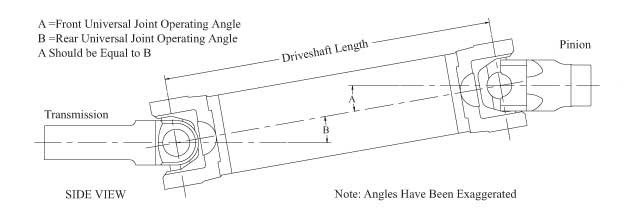
A CV joint is much more suited for large joint angles than a U joint.
And yes on the trunion part, that is exactly what I mean.
Last edited by Twin_Turbo; 07-12-2012 at 10:04 AM.
07-12-2012, 01:29 PM
#27
Supreme Member
Join Date: Apr 2002
Location: Southwest Florida
Posts: 4,627
Likes: 0
Received 1 Like
on
1 Post
Car: projects.......
Re: aligning engine/trans for motor/mid plate
But it isn�t inline with the pinion, the engine offset is around 1.5` if I remember correctly.
As for trans/crank rear end angle, that's what pinion angle is, the angle between the crank CL and pinion, not eh drivesahft and the pinion. You can ignore it, but it doesn't change what is what. In the schemaatic the resulting pinion angle = ZERO. It wasn't meant as a how to set it up for drag racing, it was meant as a how to find the pinion angle. It has nothing to do with a level floor or what not, it's simply a relationship between crank CL and the pinion. Nowhere did i say to set it up like that for drag racing, in fact I mentioned that was for my road race Corvette setup.. that's something else that dragracing no??
You want some angle on the joints or they will wear out quickly, the trunions need to work to spread the load and keep them moving.
As for trans/crank rear end angle, that's what pinion angle is, the angle between the crank CL and pinion, not eh drivesahft and the pinion. You can ignore it, but it doesn't change what is what. In the schemaatic the resulting pinion angle = ZERO. It wasn't meant as a how to set it up for drag racing, it was meant as a how to find the pinion angle. It has nothing to do with a level floor or what not, it's simply a relationship between crank CL and the pinion. Nowhere did i say to set it up like that for drag racing, in fact I mentioned that was for my road race Corvette setup.. that's something else that dragracing no??
You want some angle on the joints or they will wear out quickly, the trunions need to work to spread the load and keep them moving.
Pinion angle in drag racing is simply the angle of the pinion in relation to the driveshaft. - Unless the engine/trans is mounted at some obscene height/angle it will play little to no roll in the function of the drivetrain. The engine/trans height will not move any(no rubber mounts or stock body/chassis flex), the driveshaft stays within 1*, pinion tries to climp ring/rotate up and sqaure up to DS.
Last edited by Shagwell; 07-12-2012 at 01:37 PM.

Thread
Thread Starter
Forum
Replies
Last Post
monte87cortez
Transmissions and Drivetrain
2
09-26-2015 08:10 PM