

Trick Flow 175cc heads on 3.766" bore - valve lifts

Thread Starter
Member
Joined: Jun 2006
Posts: 307
Likes: 2
From: Troy, MI
Car: 1988 IROC-Z TBI
Engine: L04.3 = 305-310-336
Transmission: TH-700R4
Axle/Gears: 10-bolt, 3.42 posi
Trick Flow 175cc heads on 3.766" bore - valve lifts
Here are some shots of Trick Flow 175cc heads on a 305 bored 0.030" over (3.766" bore).
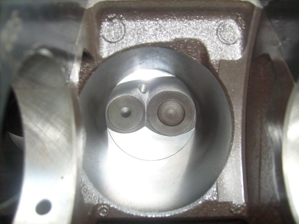
First with 1.94" and 1.50" valves seated. The combustion chambers measure 3.955" across at the widest and overhand the 3.766" bore a fair bit. The intake and exhaust valves appear equally close to the cylinder walls and the valve spacing is around 1.91"
Next, the 1.94" intake valve opened until it contacts the cylinder wall, which occurred at 0.771" lift.
The 1.50" exhaust valve opened until it contacts the cylinder wall, which occurred at 0.728" lift.
Trick Flow 175's with 2.02" intake and 1.60" exhaust valves installed on the 3.766" bore...
2.02" intake valve opened until cylinder wall contact, which occurred at 0.433" lift (which looks to be as soon as the valve cleared the chamber)...
Thread Starter
Member
Joined: Jun 2006
Posts: 307
Likes: 2
From: Troy, MI
Car: 1988 IROC-Z TBI
Engine: L04.3 = 305-310-336
Transmission: TH-700R4
Axle/Gears: 10-bolt, 3.42 posi
Re: Trick Flow 175cc heads on 3.766" bore - valve lifts
1.60" exhaust valve opened until cylinder wall contact, which occurred at 0.507" lift...
Take home:
You can use these heads, stock with 1.94" and 1.50" valves, with up to any practical maximum valve lift (0.771" and 0.728"). You can use these heads with 2.02" and 1.60" valves on a 3.766" bore as long as the valve lifts are less than 0.433" and 0.507", respectively. That doesn't consider the effects of shrouding by the close proximity to the chamber and cylinder walls. Also keep in mind that these numbers will change depending on the exact depth of your valve seats.
For comparison, I did these same fits on GM 305 '601 heads here: https://www.thirdgen.org/forums/tech...ds-1-94-a.html
In comparison with the GM heads it can be seen that Trick Flow widened the valve spacing and moved the exhaust valve closer to the chamber wall - this allows more lift with the 1.94" valve and less shrouding on the intake, but shrouds the exhaust a bit more and allows less exhaust lift with a big valve. Curiously, even though the TF head allowed more lift with a 1.94" valve than the 601, the 601 allowed more lift with a 2.02" valve than the TF, indicating that TF seem to have angled the valve slightly differently than GM, or my 601's had an "off" valve guide job.
.
Last edited by Casey Butt; Sep 16, 2009 at 05:57 PM.

Supreme Member
Joined: Sep 1999
Posts: 7,072
Likes: 13
From: Philly, PA
Re: Trick Flow 175cc heads on 3.766" bore - valve lifts
Somebody should make this a sticky. Good, real-world info with pics!
I suspect you are right about Trick Flow's attempts to unshroud the intake at the expense of the exhaust size. Shrouding an exhaust isn't as bad as shrouding an intake.
I suspect you are right about Trick Flow's attempts to unshroud the intake at the expense of the exhaust size. Shrouding an exhaust isn't as bad as shrouding an intake.
Thread Starter
Member
Joined: Jun 2006
Posts: 307
Likes: 2
From: Troy, MI
Car: 1988 IROC-Z TBI
Engine: L04.3 = 305-310-336
Transmission: TH-700R4
Axle/Gears: 10-bolt, 3.42 posi
Re: Trick Flow 175cc heads on 3.766" bore - valve lifts
I also fitted these heads with 0.030" offset locating dowels yesterday. Even though the dowels moved the heads 0.030" further "up" on the deck (towards the intake manifold), the Trick Flows still had plenty of clearance in the bolt holes to bolt on to the block just fine. Because the dowels locate the chamber closer to the center of the cylinder by 0.030" they should also unshroud the valves a little and allow a little more lift before cylinder wall contact. I didn't take valve clearance measurements at that time, though.
I'll try to get to the garage tonight and take some valve clearance measurements with the 0.030" offset dowels in place and see if they allow any significantly higher valve lift before contact.
I'll try to get to the garage tonight and take some valve clearance measurements with the 0.030" offset dowels in place and see if they allow any significantly higher valve lift before contact.

On Probation
Joined: Oct 2008
Posts: 6,319
Likes: 19
From: Northern Utah
Car: seeking '90.5-'92 'bird hardtop
Engine: several
Transmission: none
Axle/Gears: none
Re: Trick Flow 175cc heads on 3.766" bore - valve lifts
Keep in mind that using offset dowels will require machining of either the heads to accept the intake manifold and gaskets.
Thread Starter
Member
Joined: Jun 2006
Posts: 307
Likes: 2
From: Troy, MI
Car: 1988 IROC-Z TBI
Engine: L04.3 = 305-310-336
Transmission: TH-700R4
Axle/Gears: 10-bolt, 3.42 posi
Re: Trick Flow 175cc heads on 3.766" bore - valve lifts
Last edited by Casey Butt; Sep 17, 2009 at 09:25 AM. Reason: added E:I info
On Probation
Joined: Oct 2008
Posts: 6,319
Likes: 19
From: Northern Utah
Car: seeking '90.5-'92 'bird hardtop
Engine: several
Transmission: none
Axle/Gears: none
Re: Trick Flow 175cc heads on 3.766" bore - valve lifts
Part of this is because the chambers are 3.955", whereas 305 chambers are 3.73".
Trending Topics
Thread Starter
Member
Joined: Jun 2006
Posts: 307
Likes: 2
From: Troy, MI
Car: 1988 IROC-Z TBI
Engine: L04.3 = 305-310-336
Transmission: TH-700R4
Axle/Gears: 10-bolt, 3.42 posi
Re: Trick Flow 175cc heads on 3.766" bore - valve lifts
On Probation
Joined: Oct 2008
Posts: 6,319
Likes: 19
From: Northern Utah
Car: seeking '90.5-'92 'bird hardtop
Engine: several
Transmission: none
Axle/Gears: none
Re: Trick Flow 175cc heads on 3.766" bore - valve lifts
Are you thinking of doing it the way the 396 blocks had to be done to take the 2.19" intake valves?
Thread Starter
Member
Joined: Jun 2006
Posts: 307
Likes: 2
From: Troy, MI
Car: 1988 IROC-Z TBI
Engine: L04.3 = 305-310-336
Transmission: TH-700R4
Axle/Gears: 10-bolt, 3.42 posi
Re: Trick Flow 175cc heads on 3.766" bore - valve lifts
More like a more flow-friendly 45* or more grind, clearanced out 2.4 mm on each side and down a far as the top ring at TDC will allow (plus a few hundreds safety margin). I've never seen such a thing tried on a bore simulator on a flow bench, although I would suspect it would get back a good chunk of the flow lost on the 3.766" bore as compared to the 4.000" bore in Trick Flow's numbers. I've seen some Dodge 318 guys do it, but again, haven't seen any flow numbers.
Thread Starter
Member
Joined: Jun 2006
Posts: 307
Likes: 2
From: Troy, MI
Car: 1988 IROC-Z TBI
Engine: L04.3 = 305-310-336
Transmission: TH-700R4
Axle/Gears: 10-bolt, 3.42 posi
Re: Trick Flow 175cc heads on 3.766" bore - valve lifts
Here we go - looks much better...
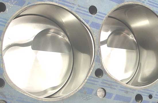
Photo is from Valako Race heads in Michigan with accompanying comment...
"This block has been bore notched to increase air flow in the cylinder. By relieving the areas near the valves there is a substantial gain in air flow resulting in added hp. Dyno tests have proven 30hp gains in smaller bore engines. When using our cylinder heads, we strongly recommend this modifaction. All of our performance engines have this, along with deburring of the tops and bottoms of the cylinder walls."
I've never bothered with this on a 305 block, but it looks like it could be in order for those doing a complete (re)build. Add in the small effect of the 0.030" offset dowels and some good flow numbers should be shaping up.
Thread Starter
Member
Joined: Jun 2006
Posts: 307
Likes: 2
From: Troy, MI
Car: 1988 IROC-Z TBI
Engine: L04.3 = 305-310-336
Transmission: TH-700R4
Axle/Gears: 10-bolt, 3.42 posi
Re: Trick Flow 175cc heads on 3.766" bore - valve lifts
Senior Member

Joined: Apr 2001
Posts: 818
Likes: 1
From: Hudson, FL USA
Car: 1988 Camaro(92 Z28 clone)
Engine: Forged 383, AFR 195 419/430@wheels
Transmission: Monster 700R4 Yank 3600 stall
Axle/Gears: 9in Detroit locker-3.90's,35 spline
Re: Trick Flow 175cc heads on 3.766" bore - valve lifts
That seems to make sense to me. When I had my Edelbrock Performer RPM heads they told you in the installation manual that if you use the 2.02/1.60 valve heads on a bore of 3.73 inches or less that valve lift had to be limited to .420 to keep the valves from contacting. Your measurement of .433 seems to fit the bill as it appears that they are taking into account that the valves will expand in size as they get hot.
On Probation
Joined: Oct 2008
Posts: 6,319
Likes: 19
From: Northern Utah
Car: seeking '90.5-'92 'bird hardtop
Engine: several
Transmission: none
Axle/Gears: none
Re: Trick Flow 175cc heads on 3.766" bore - valve lifts
I would have no hesitation about trying it to a 305 block, but trying it to the polyacrylate bore simulator sleeves is just asking for cracked polyacrylate. Having the numbers would be nice, but the dragstrip results are enough. I suppose someone could do it with wood instead of polyacrylate, maybe?
Thread Starter
Member
Joined: Jun 2006
Posts: 307
Likes: 2
From: Troy, MI
Car: 1988 IROC-Z TBI
Engine: L04.3 = 305-310-336
Transmission: TH-700R4
Axle/Gears: 10-bolt, 3.42 posi
Re: Trick Flow 175cc heads on 3.766" bore - valve lifts
Just got back from the garage... I installed the Trick Flow heads on the 3.766" bore block again, but this time with 0.030" offset head dowels to position the heads 0.030" further up on the deck (towards the intake manifold). For those who aren't familiar with this, it moves the valves away from the cylinder walls slightly and should give slightly more valve clearance and less shrouding.
With the 0.030" offset dowels in place and the heads bolted down, the 1.94" intake valve opened to 0.807" as compared to 0.771" without the offset. The 1.50" exhaust valve opened to 0.728", the same as without the offset dowel.
The 2.02" valve opened to 0.437" which is essentially the same as without the offset, indicating that contact is still likely happening as soon as the valve clears the chamber. The 1.60" exhaust valve opened to 0.602" with the offset dowel as compared to 0.507" without the offset.
Summary - Trick Flow 175cc heads on 3.766" bore:
Standard head placement max. lifts
1.94" -- 0.771"
1.50" -- 0.728"
2.02" -- 0.433"
1.60" -- 0.507"
With 0.030" offset dowels max. lifts
1.94" -- 0.807"
1.50" -- 0.728"
2.02" -- 0.437"
1.60" -- 0.602"
It looks like the 0.030" offset allowed 0.036" extra lift on the 1.94" intake valve and a huge 0.095" extra lift on the 1.60" exhaust valve. Oddly, the offset didn't seem to affect the maximum lift with the 1.50" valve - but the lifts involved were well past retainer-seal contact anyway, so it's largely irrelevant. The 2.02" intake valve still looks to be not clearing the bore at all and makes contact as soon as it lifts out of the combustion chamber.
In any case, it appears as though the offset dowels are a worthy "trick" to use on small bore engines to get a little extra valve clearance. The Trick Flow's had sufficiently big head bolt holes to allow the heads to bolt to the deck just fine even though they were shifted 0.030" up on the deck, this might not be the case with GM or other aftermarket heads and they might require all the bolt holes to be bored out slightly in order for the bolts to line up with the block. I had absolutely no problems with the Trick Flow 175's in this regard.
Also, like Atilla said, with the heads offset 0.030" each, the intake manifold might be squeezed to fit properly and either the heads or intake manifold will likely need to be milled at the mating surfaces to re-establish the proper fit. I haven't tried to bolt up an intake manifold with the heads offset as of yet.
Supreme Member
Joined: Sep 1999
Posts: 7,072
Likes: 13
From: Philly, PA
Re: Trick Flow 175cc heads on 3.766" bore - valve lifts
Casey- this is solid research in my book. If this doesn't get made into a sticky it'll be a shame.
This certainly helps explain why installing bigger valves in a stock 305 head (particularly a 1.60 exhaust, but also a 1.94 intake) would boost performance on a 305 with very little downside. Something that doesn't necessarily get you the same results from an aftermarket head.
One more, please, if you've got ready access to a set of 350 Vortec heads. I'll bet you dollars to donuts they moved the valves around in a way similar to the aftermarket Trick Flow heads. I've built a few engines with Vortecs and there is definitely some kind of movement of the valves vs. an older stock head. Lotsa guys on this board build Vortec-headed engines. Very few will ever build a motor using those TrickFlow heads. (The pic you swiped above of a stock head definitely isn't a Vortec 350 head- chambers aren't heart-shaped)
As a side note, I did similar observations on a 454 big block I built recently using AFR heads. Totally different engine, obviously, but lots of basic similarities. Chambers overhanging the bores, intake valves close to the bore wall, valves moved around slightly from the stock locations. That kinda stuff. Wish I had taken pictures. My general overall conclusion was "man, these heads would work a lot better on a bigger bore!" In the big block world NOBODY wastes their time with a little 454 any more (4.25" bore). Anyone serious about things starts with a bigger 4.5" bore block (502 or more cubes). And that seems to be what the heads are really designed for. AFR claims their heads will work on anything down to a 396. Yeah, well, good luck using them on anything smaller than a 427 becuase the intake valves just ain't gonna fit very far down the bore of a little pea-shooter 396.
Last edited by Damon; Sep 17, 2009 at 10:35 PM.
Thread Starter
Member
Joined: Jun 2006
Posts: 307
Likes: 2
From: Troy, MI
Car: 1988 IROC-Z TBI
Engine: L04.3 = 305-310-336
Transmission: TH-700R4
Axle/Gears: 10-bolt, 3.42 posi
Re: Trick Flow 175cc heads on 3.766" bore - valve lifts
To go along with the flow data of the TFS 175cc heads...
I measured the pushrod pinch area in these heads at 1.86 - 1.89 in^2 (depending on how well I could line up the gauge) - which should be enough to take a 305 to 7300-7400 rpm at peak horsepower, a 350 to 6350-6450 rpm at peak hp, and a 383 to 5800-5900 rpm at peak hp.
I measured the pushrod pinch area in these heads at 1.86 - 1.89 in^2 (depending on how well I could line up the gauge) - which should be enough to take a 305 to 7300-7400 rpm at peak horsepower, a 350 to 6350-6450 rpm at peak hp, and a 383 to 5800-5900 rpm at peak hp.
On Probation
Joined: Oct 2008
Posts: 6,319
Likes: 19
From: Northern Utah
Car: seeking '90.5-'92 'bird hardtop
Engine: several
Transmission: none
Axle/Gears: none
Re: Trick Flow 175cc heads on 3.766" bore - valve lifts
something is wrong with your figuring, real dyno testing proves that getting the results you say would require at least something like AFR's 195cc head. You sure won't get your predicted results with these heads.
Thread Starter
Member
Joined: Jun 2006
Posts: 307
Likes: 2
From: Troy, MI
Car: 1988 IROC-Z TBI
Engine: L04.3 = 305-310-336
Transmission: TH-700R4
Axle/Gears: 10-bolt, 3.42 posi
Re: Trick Flow 175cc heads on 3.766" bore - valve lifts
minimum port area = rpm*stroke*bore^2/C
where C can be anything from 177000 to 196000 - I used 190000 in the calculations because it's most typical of a high-performance hyd. roller cam.
The formula doesn't mean that the engine will actually peak at that rpm, but that the head is capable of supporting such a peak given the proper cam, exhaust, intake, etc. What the formula does calculate is the cross-sectional area at which airflow in the head reaches terminal velocity (0.55 to 0.60 times the speed of sound) - and airflow speed will not increase past that point, so that denotes the maximum possible peak hp rpm limit. The maximum rpm given is the physical limit of the head on a given engine, not saying an engine will reach that max rpm simply because it has those heads installed.
AFR 195's have a cross-sectional area of 1.98 sq.in, so assuming a correspondingly "larger" cam, exhaust, etc, they would push the potential maximum peak hp rpm point higher.
Last edited by Casey Butt; Sep 25, 2009 at 05:57 PM.
On Probation
Joined: Oct 2008
Posts: 6,319
Likes: 19
From: Northern Utah
Car: seeking '90.5-'92 'bird hardtop
Engine: several
Transmission: none
Axle/Gears: none
Re: Trick Flow 175cc heads on 3.766" bore - valve lifts
I played with all of these old ideas back when I was new to performance engines, many years ago. These formulas are leftovers from the sixties, when heads didn't flow, and a huge duration, solid-lifter cam was the only way to make a big peak HP number. Nevermind that you had to keep the engine within 500 rpm of that. Rev any higher, you're past what the head flow can support. rev any lower, you're out of the rpm range where the cam works.
These TFS 175 heads, as they come out of TFS's box, will be okay to 5500 on a 383, but the AFR195 would surpass them as low as 3000 rpm. Throw out those old formulas and embrace modern things. Find a dyno result sheet you like, from a test done within the last 5 years, and copy that. Unless you have a dyno yourself, you can't do any better.
These TFS 175 heads, as they come out of TFS's box, will be okay to 5500 on a 383, but the AFR195 would surpass them as low as 3000 rpm. Throw out those old formulas and embrace modern things. Find a dyno result sheet you like, from a test done within the last 5 years, and copy that. Unless you have a dyno yourself, you can't do any better.
Thread Starter
Member
Joined: Jun 2006
Posts: 307
Likes: 2
From: Troy, MI
Car: 1988 IROC-Z TBI
Engine: L04.3 = 305-310-336
Transmission: TH-700R4
Axle/Gears: 10-bolt, 3.42 posi
Re: Trick Flow 175cc heads on 3.766" bore - valve lifts
Actually, as a GM Powertrain Engineer whose job it is to mathematically model engines and electric motors, I can assure you that those equations are used in current mathematical modeling and are anything but relics from the 1960s. Yes, the equations themselves are simplifications and are not on the level of sophistication as say wave analysis, but are in the ballpark for guideline purposes if the correct constant is chosen - although head design (and everything else) certainly has improved, the physics governing them hasn't changed.
The theoretical underpinnings provide direction and clues into what's actually happening in an engine, but I certainly agree that dyno results trump everything.
The theoretical underpinnings provide direction and clues into what's actually happening in an engine, but I certainly agree that dyno results trump everything.
Member
Joined: Jan 2008
Posts: 249
Likes: 0
Car: 1989 Firebird Formula
Engine: 310 HSR, TFS heads, zz4 cam
Transmission: T5
Axle/Gears: 9 bolt 3:70
Re: Trick Flow 175cc heads on 3.766" bore - valve lifts
sorry to bring this thread back to life but your obviously highly experienced with these heads... I need to use a 350 head gasket on my 310 with these heads correct?
That wont cause any issues will it?
That wont cause any issues will it?
On Probation
Joined: Oct 2008
Posts: 6,319
Likes: 19
From: Northern Utah
Car: seeking '90.5-'92 'bird hardtop
Engine: several
Transmission: none
Axle/Gears: none
Re: Trick Flow 175cc heads on 3.766" bore - valve lifts
Unless your block has been decked, use FelPro 1094 gaskets.
Member
Joined: Jan 2008
Posts: 249
Likes: 0
Car: 1989 Firebird Formula
Engine: 310 HSR, TFS heads, zz4 cam
Transmission: T5
Axle/Gears: 9 bolt 3:70
Re: Trick Flow 175cc heads on 3.766" bore - valve lifts
nope, hasnt been decked.
should i try a thinner gasket to improve compression?
also, do i need shims for the rocker arms or guideplates?
should i try a thinner gasket to improve compression?
also, do i need shims for the rocker arms or guideplates?
Last edited by Nater36; Jul 17, 2010 at 09:59 AM.
On Probation
Joined: Oct 2008
Posts: 6,319
Likes: 19
From: Northern Utah
Car: seeking '90.5-'92 'bird hardtop
Engine: several
Transmission: none
Axle/Gears: none
Re: Trick Flow 175cc heads on 3.766" bore - valve lifts
IF you can find ANY head gasket thinner than the 1094, please share.
Member
Joined: Jan 2008
Posts: 249
Likes: 0
Car: 1989 Firebird Formula
Engine: 310 HSR, TFS heads, zz4 cam
Transmission: T5
Axle/Gears: 9 bolt 3:70
Re: Trick Flow 175cc heads on 3.766" bore - valve lifts
do ineed guideplates or shims? or are these a straight swap
Last edited by Nater36; Jul 18, 2010 at 06:19 AM.


Senior Member
Joined: Jun 2010
Posts: 731
Likes: 1
From: Austin, TX
Car: 1989 G92 IROC-Z
Engine: 5 Liter 305
Transmission: T5
Axle/Gears: 3.45
Re: Trick Flow 175cc heads on 3.766" bore - valve lifts
It's tech like this that makes this board nice. Pure fun to mess around and see whats really going on. That being said, this should probably be easier to find IMO. Sticky?
Anyway, there is A LOT of speculation floating on the net about which valve works at what lifts when it comes to the small bore 305. I am REALLY wondering how different the valve placement is in Vortec 059/906's compared to the heads in this thread...? Reason being, I just tried to get some EQ Vortecs for my G92 305 rebuild from Rogers Performance http://www.rogersperformance.com/EQ.htm - and was told the Vortecs with 1.94 valves will hit the cylinder walls at anything above .520 lift.
After calling Mike Rogers, he explained to me that he runs Racesavers and they are limited to this lift when using their cams. So there actually may or may not be something to this rule.
The problem is using a 64cc head on a 305 loses compression compared to a 56cc head. In trying to "correct" the issue by milling the head this valve to cylinder wall contact issue may be magnified by actually putting the guide closer to the wall thus causing earlier contact. The geometry would be changed.
It was explained in post#4 @ https://www.thirdgen.org/forums/tech...ds-1-94-a.html that the head gasket wouldn't matter and that the valve geometry would be unaffected. I see that point considering valve placement in the cylinder centerline is the same but wouldn't it be the offset that the valves have in the chamber being changed when not using a head gasket vs using a gasket? In other words, if there was no combustion chamber and the seat was level with the deck, at a given geometry, getting the valve off the seat would cause contact sooner by moving the bottom of the guide that much closer to the cylinder wall. Follow? Were trying to get the valve off the seat thus increasing potential lift - so is it safe to assume a head gasket actually can change that number?
I know there's only one way to find out but since were already on the subject...
Thread Starter
Member
Joined: Jun 2006
Posts: 307
Likes: 2
From: Troy, MI
Car: 1988 IROC-Z TBI
Engine: L04.3 = 305-310-336
Transmission: TH-700R4
Axle/Gears: 10-bolt, 3.42 posi
Re: Trick Flow 175cc heads on 3.766" bore - valve lifts
Well, it's been awhile (almost 4 years) and the engine's been together and back apart by now but I guess an update wouldn't hurt...
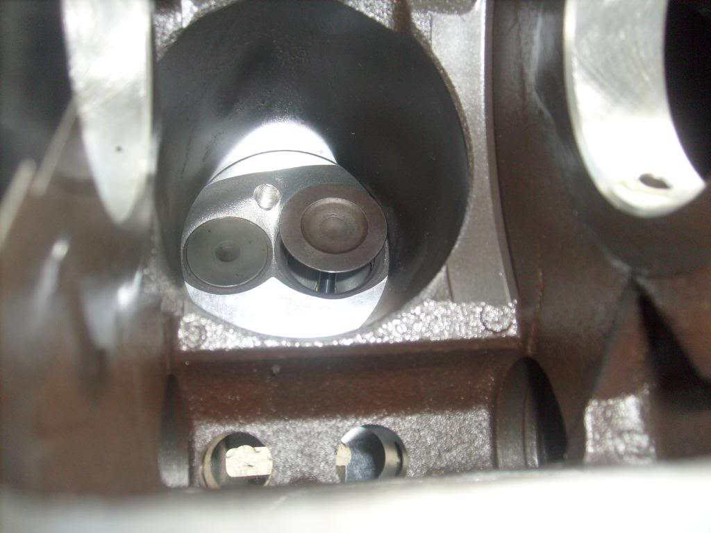
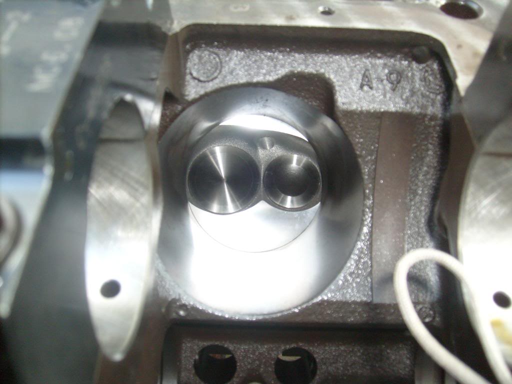
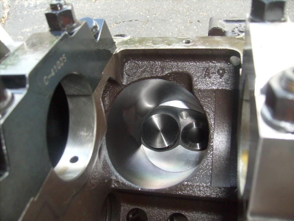
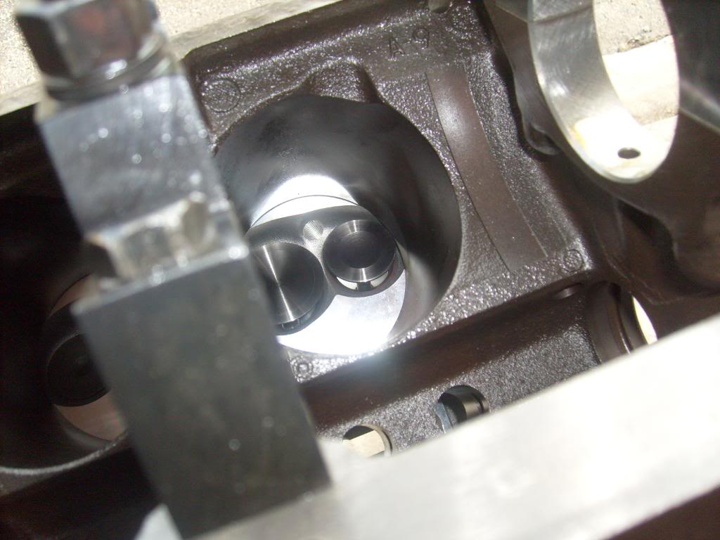
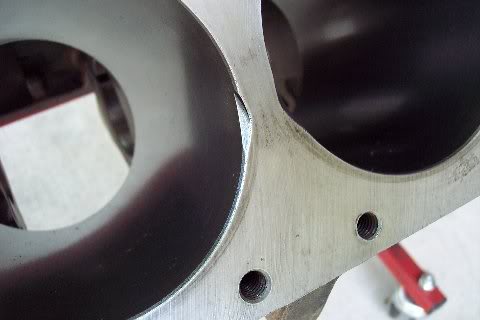
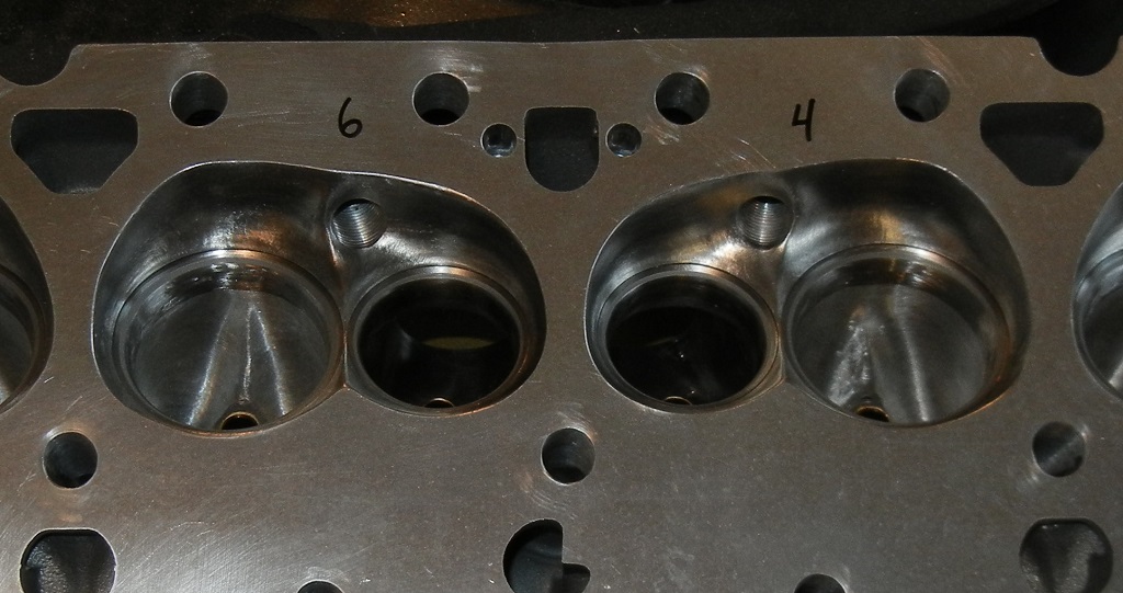
I ended up going with 1.97" and 1.56" valves on the Trick Flows, ported them some and "notched" around the bores of the 305 (actually a 3.776" bore now) to match the chambers of the Trick Flows. Here are the finished chambers...
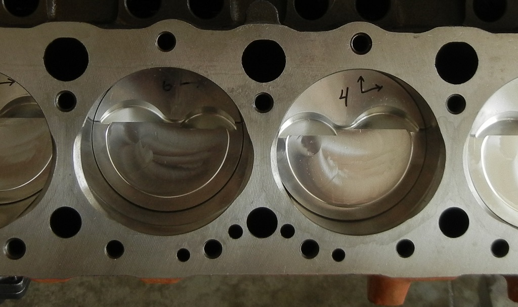
These are the matching cylinders...
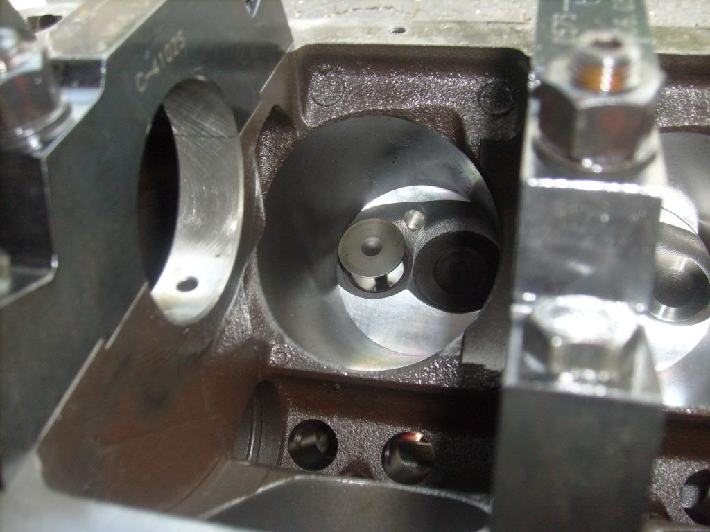
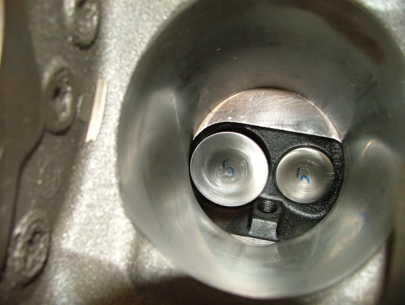
And this is how the heads look installed on the block...

Valves opened 'till contact...
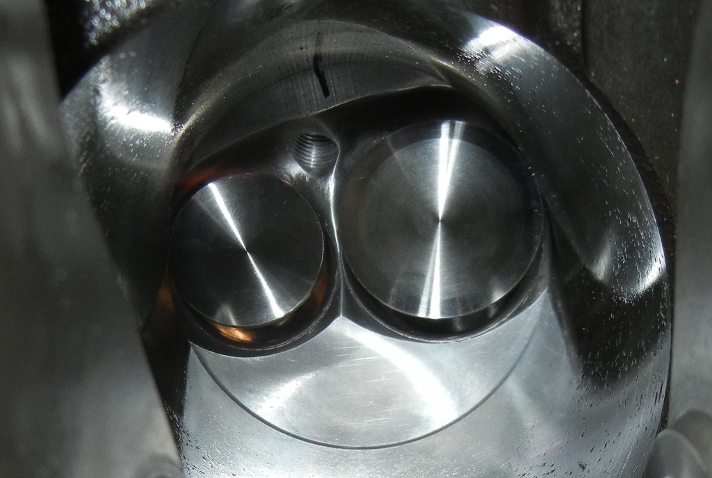
With these modifications done, using the 0.030" offset dowels and with 0.040" quench distance, the 1.97" intake valve opens to 0.689" until it contacts the bore and the 1.56" exhaust opens to 0.669".
I know that doesn't necessarily translate to other heads but it's here for anyone considering using the Trick Flow 175's on a 305 or just interested in general.
By the way, the 1.97" intake valves are Manleys that had to be cut down and the 1.56" exhausts are F6161 Ferreas.
I ended up going with 1.97" and 1.56" valves on the Trick Flows, ported them some and "notched" around the bores of the 305 (actually a 3.776" bore now) to match the chambers of the Trick Flows. Here are the finished chambers...
These are the matching cylinders...
And this is how the heads look installed on the block...
Valves opened 'till contact...
With these modifications done, using the 0.030" offset dowels and with 0.040" quench distance, the 1.97" intake valve opens to 0.689" until it contacts the bore and the 1.56" exhaust opens to 0.669".
I know that doesn't necessarily translate to other heads but it's here for anyone considering using the Trick Flow 175's on a 305 or just interested in general.
By the way, the 1.97" intake valves are Manleys that had to be cut down and the 1.56" exhausts are F6161 Ferreas.
Last edited by Casey Butt; Jun 24, 2013 at 12:02 PM.
Senior Member
Joined: Jun 2010
Posts: 731
Likes: 1
From: Austin, TX
Car: 1989 G92 IROC-Z
Engine: 5 Liter 305
Transmission: T5
Axle/Gears: 3.45
Re: Trick Flow 175cc heads on 3.766" bore - valve lifts
How does the head gasket look over the notched cylinder bores? Which head gasket are you using?
No, it doesn't help me out with the vortecs but its still interesting. I debate between both heads. Cost wise, it's not really that far apart considering the intake, shipping, machine work etc.
No, it doesn't help me out with the vortecs but its still interesting. I debate between both heads. Cost wise, it's not really that far apart considering the intake, shipping, machine work etc.
Thread Starter
Member
Joined: Jun 2006
Posts: 307
Likes: 2
From: Troy, MI
Car: 1988 IROC-Z TBI
Engine: L04.3 = 305-310-336
Transmission: TH-700R4
Axle/Gears: 10-bolt, 3.42 posi
Re: Trick Flow 175cc heads on 3.766" bore - valve lifts
How does the head gasket look over the notched cylinder bores? Which head gasket are you using?
No, it doesn't help me out with the vortecs but its still interesting. I debate between both heads. Cost wise, it's not really that far apart considering the intake, shipping, machine work etc.
No, it doesn't help me out with the vortecs but its still interesting. I debate between both heads. Cost wise, it's not really that far apart considering the intake, shipping, machine work etc.
Senior Member
Joined: Jun 2010
Posts: 731
Likes: 1
From: Austin, TX
Car: 1989 G92 IROC-Z
Engine: 5 Liter 305
Transmission: T5
Axle/Gears: 3.45
Re: Trick Flow 175cc heads on 3.766" bore - valve lifts
I was just wondering how bad the ridge was where the bores werent notched. It looks like the Valako pic shows a special gasket thats matched to the bores perfectly.
Thread Starter
Member
Joined: Jun 2006
Posts: 307
Likes: 2
From: Troy, MI
Car: 1988 IROC-Z TBI
Engine: L04.3 = 305-310-336
Transmission: TH-700R4
Axle/Gears: 10-bolt, 3.42 posi
Re: Trick Flow 175cc heads on 3.766" bore - valve lifts
I made the notches with a cutter and then switched to a cartridge roll to smooth out the final shape and blend the edges in nicely. No ridges at all. It turned out really well... I used Dykem and matched each bore to the corresponding chamber perfectly.


Joined: Sep 2003
Posts: 25,895
Likes: 429
From: Pittsburgh PA
Car: 89 Iroc-z
Engine: 555 BBC Turbo
Transmission: TH400
Axle/Gears: MWC 9� 3.00
Re: Trick Flow 175cc heads on 3.766" bore - valve lifts
Has engine been run in the previous 4 yrs? Curious what the final combo looked like and what power it made
Thread Starter
Member
Joined: Jun 2006
Posts: 307
Likes: 2
From: Troy, MI
Car: 1988 IROC-Z TBI
Engine: L04.3 = 305-310-336
Transmission: TH-700R4
Axle/Gears: 10-bolt, 3.42 posi

Joined: Feb 2008
Posts: 213
Likes: 1
From: Woodstock, GA
Car: 1989 IROC
Engine: 305 TPI
Transmission: T-5
Axle/Gears: 3.23
Re: Trick Flow 175cc heads on 3.766" bore - valve lifts
I was looking to use the following on my 305. The Comp Camstech said I would need to check valve to piston clearance. Would this be thecase with the following additions? I ask as it looks like you have tried thesame heads on a 305.
Comp Cams Cam CCA-08-501-8 Camshaft, Hydraulic RollerTappet, and Advertised Duration 264/269, Lift .488/.495.
EagleStreet and Strip Rotating Assemblies B13101L03053
Piston Head Volume (cc):+5.00cc
Bore (in):3.766in.
Cylinder Heads Trick Flow TFS-30300007
Intake Valve Diameter (in):1.940in.
Exhaust Valve Diameter(in):1.500 in.
Maximum Valve Lift (in):0.600in.
COMP Cams Magnum Steel Roller Tip Rocker Arms 1412-16
Rocker Arms, Stud Mount, Roller Tip, Steel, 1.52 Ratio
Last edited by FUNIROC; Jul 3, 2013 at 06:40 PM.
Supreme Member
iTrader: (-3)
Joined: Dec 2012
Posts: 1,184
Likes: 1
Car: 1991 firebird
Engine: TBI 305 (built)
Transmission: T5
Axle/Gears: 4.10
Re: Trick Flow 175cc heads on 3.766" bore - valve lifts
I actually just ordered these same exact heads for my .030 over 305 that I am in the process of rebuilding ! Ill try to keep this short
Here is my combo -
Summit stage 1 dual plane idle-6000 (ported) , TFS 175 heads, Howard's cam .488I .495E 213/218 @.050 114LSA 110ICL , 1.6 full rollers , speed pro hyper flat tops 5cc valve reliefs , double roller timing set , 1 5/8-1 3/4 stepped shorties full 3" exhaust w/ y-dump, ALL transitions gasket matched , stock crank & rods (balanced) , & a 100 shot a spray .....I'm really wanting 350/350 HP/TQ out of this thing on motor ... What do y'all think ? And after reading this I'm thinkin about notching the top of the cylinders as shown here ... How hard was it ? Did u use a carbide burr ? Then a cartridge roll ... Any suggestions on my above build would be greatly apretiated !
Thread Starter
Member
Joined: Jun 2006
Posts: 307
Likes: 2
From: Troy, MI
Car: 1988 IROC-Z TBI
Engine: L04.3 = 305-310-336
Transmission: TH-700R4
Axle/Gears: 10-bolt, 3.42 posi
Re: Trick Flow 175cc heads on 3.766" bore - valve lifts
I actually just ordered these same exact heads for my .030 over 305 that I am in the process of rebuilding ! Ill try to keep this short
Here is my combo -
Summit stage 1 dual plane idle-6000 (ported) , TFS 175 heads, Howard's cam .488I .495E 213/218 @.050 114LSA 110ICL , 1.6 full rollers , speed pro hyper flat tops 5cc valve reliefs , double roller timing set , 1 5/8-1 3/4 stepped shorties full 3" exhaust w/ y-dump, ALL transitions gasket matched , stock crank & rods (balanced) , & a 100 shot a spray .....I'm really wanting 350/350 HP/TQ out of this thing on motor ... What do y'all think ?
And after reading this I'm thinkin about notching the top of the cylinders as shown here ... How hard was it ? Did u use a carbide burr ? Then a cartridge roll ...
It's not at all difficult. A good cutter will go through the edges of the bores like butter. But it is precise and it is a dangerous game to play - one wrong move with the cutter and you can render the block useless. I have no way to test it, but I have no doubt that there's a notable flow improvement to be had by doing it - not only in terms of de-shrouding the valves but one look at that horrible ledge between the bore and chamber and you can see the "problem". There is a risk involved to "fix" it though.
Supreme Member
iTrader: (-3)
Joined: Dec 2012
Posts: 1,184
Likes: 1
Car: 1991 firebird
Engine: TBI 305 (built)
Transmission: T5
Axle/Gears: 4.10
Re: Trick Flow 175cc heads on 3.766" bore - valve lifts
Cool man .. I think I can handle it I have some experience with carbide cutters and also have a fairly steady hand .... Another ? I've been looking for someone to answer ---> I have an adjustable billet timing set 8* either way ... I was thinking about installing the cam at a 108 ICL ? Anyone have a suggestion on cam timing ? Thanks again .... Also if u would be interested in more detail on my build look up "LO3 rebuild (HP Estimates)" in the TBI section ... I would appreciate any input alot !
P.S. - I'm wanting to get around 8.000's in 1/8th out of this build ON MOTOR ONLY ... I ran a 9.80 last time at the track with bone stock engine besides throttle body , CAI, 1.6 rockers , 1 1/2" shorties & full 3" exhaust dumped at axle ... And still could have got a tenth or two out of it with some more tuning I believe !
P.S. - I'm wanting to get around 8.000's in 1/8th out of this build ON MOTOR ONLY ... I ran a 9.80 last time at the track with bone stock engine besides throttle body , CAI, 1.6 rockers , 1 1/2" shorties & full 3" exhaust dumped at axle ... And still could have got a tenth or two out of it with some more tuning I believe !
Last edited by 1991sleeper; Aug 3, 2013 at 07:30 PM.

Thread
Thread Starter
Forum
Replies
Last Post
Mickeyruder
Engine/Drivetrain/Suspension Parts for Sale
3
Sep 2, 2015 02:45 PM