
Did I get the right parts(870-165ecm)


Thread Starter
Senior Member
Joined: Aug 2001
Posts: 610
Likes: 0
From: fredericksburg, va
Car: 85 ta ws6 KITT
Engine: Lb9
Transmission: th350
Did I get the right parts(870-165ecm)
Went to a junk yard and got these for $20, didn't think to check the vin 1st ..oh well, it was only $20.
I tried to find the tarelay picture so i could compare, but couldn't find it.
Can anyone identify these in a jiffy? I'm not so much interested in the relays b/c i can buy them new if needs be, but rather, i want to make sure i have the correct harness.
..oh well, it was only $20.I tried to find the tarelay picture so i could compare, but couldn't find it.
Can anyone identify these in a jiffy? I'm not so much interested in the relays b/c i can buy them new if needs be, but rather, i want to make sure i have the correct harness.

Supreme Member
Joined: Jun 2000
Posts: 7,554
Likes: 1
From: In reality
Car: An Ol Buick
Engine: Vsick
Transmission: Janis Tranny Yank Converter
Which ecm do you want to use?.
85-89 has two ecm connectors.
90-92 is 3.
I see a MAP sensor, so it should have 3 ecm connectors.
Being's a 730 application, (3 connector), you should have just 8 injector connectors. 85-88 had 9.
I can't see enough detail to really tell you if you got the right one or not.
For $20, I'll take one
85-89 has two ecm connectors.
90-92 is 3.
I see a MAP sensor, so it should have 3 ecm connectors.
Being's a 730 application, (3 connector), you should have just 8 injector connectors. 85-88 had 9.
I can't see enough detail to really tell you if you got the right one or not.
For $20, I'll take one
Member
Joined: Nov 2003
Posts: 299
Likes: 0
From: The Netherlands
Car: Cobra Kit Car
Engine: 350 HSR
Transmission: TKO 600
Axle/Gears: 3.31
I think that you miss a lot to make a 165 TPI, if that is the goal.
I don't know for a TBI but I have put a readable picture on my site for the big connector on the left side.
I use the book of a 1987 Camaro.
To download from the site just hit the:
http://www.donostia.demon.nl/Image002.jpg
it is 1.5 Mb.
A smaller version you can see here.
I hope that this will help you.
Regards,
Cobra289
Thread Starter
Senior Member
Joined: Aug 2001
Posts: 610
Likes: 0
From: fredericksburg, va
Car: 85 ta ws6 KITT
Engine: Lb9
Transmission: th350
hmm...i'll try to get better pics.
if it's the wrong harness, i'll straight up trade you for the correct one, grumpy . i'm trying to go from 870 to 165...maybe i could go 870 to 730? i imagine from pos maf to SD would be a big jump, and means i need more parts. i already have the 165 ecm too
and cobra...you could tell me that pic is used to make spaceships, and i'd believe you.
if it's the wrong harness, i'll straight up trade you for the correct one, grumpy
. i'm trying to go from 870 to 165...maybe i could go 870 to 730? i imagine from pos maf to SD would be a big jump, and means i need more parts. i already have the 165 ecm tooand cobra...you could tell me that pic is used to make spaceships, and i'd believe you.
Last edited by N8MAN1068; May 13, 2004 at 06:53 PM.

Member
Joined: Nov 2003
Posts: 462
Likes: 1
From: Ft. Leavenworth, KS
Car: 83 TA, 89 TTA, others
Engine: ZZ4 TPI, LC2 turbo v6
Transmission: several, mostly broken
If you've already got an '870 car, you shouldn't need a whole new harness, just a few changes to the one you have.
http://www.eecis.udel.edu/~davis/z28/ecm_swap/
The '870 to '165 conversion is more involved than the 165 to 730 conversion. Once you've updated your '870 harness to '165 configuration, further modifying it to SD is a piece of cake.
Also, don't worry about the C100 connector -- starting with an F-body basically takes care of that for you. Even when I converted my carbureted '83 LG4 to TPI, I didn't have to change anything in C100. IIRC there's like one wire different between TPI and some of the TBI cars, but that's about it.

Member
Joined: May 2003
Posts: 263
Likes: 0
From: Lakeland,Florida
If your looking for the harness that the Davis site says is "required", you dont need it. When I swapped my 870 for 165 I bought the relay plugs from NAPA for like $6 each. I bought new relays at Advance Auto parts (it was difficult to find them- actually look them up). The NAPA plugs have plenty of length, and when I unplugged my factory 870 burnoff- there was enough wire between the two of them to do the job. I mounted my new relays right where my 870 burnoff went. This was on my 85 Vette, a Camaro Firebird may be a little different- I dont know. Other than finding the right relays it was a piece of cake.
Thread Starter
Senior Member
Joined: Aug 2001
Posts: 610
Likes: 0
From: fredericksburg, va
Car: 85 ta ws6 KITT
Engine: Lb9
Transmission: th350
so then all i need is the relays, and not the harness?
sbnova...can i im/email you about this? it's hard to get ahold of people who've actually done this.
my email is n8man1068@yahoo.com, aol/aim is N8MAN1068.
thanks.
sbnova...can i im/email you about this? it's hard to get ahold of people who've actually done this.
my email is n8man1068@yahoo.com, aol/aim is N8MAN1068.
thanks.
Trending Topics

Junior Member
Joined: Sep 2001
Posts: 83
Likes: 0
From: Somerset,NJ 08873
Hi. Nice combo probably like mine ;just lacking that little bit from Good to Smoking Gobs of Power( I get high from laying rubber/ Real Street Performance)  . You need the ECM pinouts for the diffrent configurations of the ECM Plugs. Put them together and figure out which pins are moved and where;I marked up the ECM pinout diagram with my changes and color codes too allow future refrence. In addition and sensors which have signal inputs into the ECM will require a connection to the 5 volt and signal grounds into/or at the ECM. I found to switch my car between a 730- $58, 165 - $6E , and $5D - 808 code and pinouts can be completed with just unplugging adapters. You might want to consider the 7808 computer w $5D map or $12 their a bit diffrent but have useable features available like a BPW closed loop / open loop Aussie setup it has even less wires and has better resolution. If you are considering the 7730 the 808 is fewer connections.
Do a search on the diffrent keywords and youll find some useful info.
Ed
. You need the ECM pinouts for the diffrent configurations of the ECM Plugs. Put them together and figure out which pins are moved and where;I marked up the ECM pinout diagram with my changes and color codes too allow future refrence. In addition and sensors which have signal inputs into the ECM will require a connection to the 5 volt and signal grounds into/or at the ECM. I found to switch my car between a 730- $58, 165 - $6E , and $5D - 808 code and pinouts can be completed with just unplugging adapters. You might want to consider the 7808 computer w $5D map or $12 their a bit diffrent but have useable features available like a BPW closed loop / open loop Aussie setup it has even less wires and has better resolution. If you are considering the 7730 the 808 is fewer connections. Do a search on the diffrent keywords and youll find some useful info.
Ed

Supreme Member
Joined: May 2002
Posts: 4,099
Likes: 2
Originally posted by N8MAN1068
so then all i need is the relays, and not the harness?
sbnova...can i im/email you about this? it's hard to get ahold of people who've actually done this.
my email is n8man1068@yahoo.com, aol/aim is N8MAN1068.
thanks.
so then all i need is the relays, and not the harness?
sbnova...can i im/email you about this? it's hard to get ahold of people who've actually done this.
my email is n8man1068@yahoo.com, aol/aim is N8MAN1068.
thanks.
Junior Member
Joined: Sep 2001
Posts: 83
Likes: 0
From: Somerset,NJ 08873
Oh yeah the only obvious disadvantage is the 160 baud vs 8192 in a 7730 MAP / 7165 - MAF.
Ed
Grumpys says that you should always datalog and review while keep notes.Thus making the 160 baud in the 808 code just fine for simplicity and getting data.
Ed
Grumpys says that you should always datalog and review while keep notes.Thus making the 160 baud in the 808 code just fine for simplicity and getting data.
Supreme Member
Joined: May 2002
Posts: 4,099
Likes: 2
Originally posted by edfirebird
Oh yeah the only obvious disadvantage is the 160 baud vs 8192 in a 7730 MAP / 7165 - MAF.
Ed
Grumpys says that you should always datalog and review while keep notes.Thus making the 160 baud in the 808 code just fine for simplicity and getting data.
Oh yeah the only obvious disadvantage is the 160 baud vs 8192 in a 7730 MAP / 7165 - MAF.
Ed
Grumpys says that you should always datalog and review while keep notes.Thus making the 160 baud in the 808 code just fine for simplicity and getting data.
Member
Joined: Nov 2003
Posts: 462
Likes: 1
From: Ft. Leavenworth, KS
Car: 83 TA, 89 TTA, others
Engine: ZZ4 TPI, LC2 turbo v6
Transmission: several, mostly broken
Originally posted by edfirebird
Grumpys says that you should always datalog and review while keep notes.Thus making the 160 baud in the 808 code just fine for simplicity and getting data.
Grumpys says that you should always datalog and review while keep notes.Thus making the 160 baud in the 808 code just fine for simplicity and getting data.
Especially once you start trying to tune AE and transitional stuff. A lot can happen, in between frames at 160.
Given the choice, 8192 is the way to go, if you're going to depend on the ALDL for datalogging.
Junior Member
Joined: Sep 2001
Posts: 83
Likes: 0
From: Somerset,NJ 08873
I agree. I'm all about faster baud rates. The 808 code didnt support the high speed uart in our 1227165. Even though the hardware does. If he allready had a 7165 ecm I was just suggesting an eaiser hook up. Hope fully some one find's a way to patch the serial code from like a 6E or 32B to the 5D(808 Aussie). The aussies had later code w/ better resolution for tables and 8192 there's just limited ECM/ DEFs avail for us noobies.
Ed
Ed
Last edited by edfirebird; May 16, 2004 at 08:58 PM.
Thread Starter
Senior Member
Joined: Aug 2001
Posts: 610
Likes: 0
From: fredericksburg, va
Car: 85 ta ws6 KITT
Engine: Lb9
Transmission: th350
man, ya'll are speaking greek....
so when i get the relay's and matching pigtails (is there another term for this, so i dont sound like a moron at autozone asking for these?), are the pigtails color coded? while i'm pretty new to this, i can still put 2 diagrams together, look at the pretty colors and see where they need to go.
if all this extra wiring isn't necesarry, someone should tell that guy so they can update the tech article so people like me don't spend a long time searching for an uncut harness.
thanks again:hail:
Supreme Member
Joined: May 2002
Posts: 4,099
Likes: 2
Originally posted by N8MAN1068
man, ya'll are speaking greek....
so when i get the relay's and matching pigtails (is there another term for this, so i dont sound like a moron at autozone asking for these?), are the pigtails color coded? while i'm pretty new to this, i can still put 2 diagrams together, look at the pretty colors and see where they need to go.
if all this extra wiring isn't necesarry, someone should tell that guy so they can update the tech article so people like me don't spend a long time searching for an uncut harness.
thanks again:hail:
Thread Starter
Senior Member
Joined: Aug 2001
Posts: 610
Likes: 0
From: fredericksburg, va
Car: 85 ta ws6 KITT
Engine: Lb9
Transmission: th350
yes i did sbnova, and thanks.
i replied to the email, but figured i'd also put it in here in case anyone else can get usefull info from this.
you stated that i don't need the old harness, but the links also refer to pin swapping. could i not just splice the pigtail leads into the harness? (now that i think about it, probably not). or maybe solder the pins directly to the leads, and plug it into the correct harness socket?
Junior Member
Joined: Sep 2001
Posts: 83
Likes: 0
From: Somerset,NJ 08873
The old harness is usable if you take both ECM pinouts and schematics for the car. Then determine which wires need to be moved in the ECM pin header(pin swaping). Any wires which need to be connected to a new relay can be wired in into the existing harness. Any relays added If you removed one and have the schematic you would know which wire went to what( batt, pin at ecm, fuse box .... Then make your connections using the existing wires or your new 2 you harness( off the donor car). Just keep the color code true to OEM specs and you can diag your car if necessary in the future. The existing harness might have the pins in the right spot for some things! I habvent seen both ecm 870 and 165 side by side but It is possible.
This keeps the original wiring intact as much as possible to avoid a lot of splicing which can all bite you in the butt later. (Solder all you connects then use really good tape strech while wrapping and or heatshrink tube.
The davis site has a pin swapping guide bewteen the pinout for a 870 and 165.
Ed
Junior Member
Joined: Sep 2001
Posts: 83
Likes: 0
From: Somerset,NJ 08873
Go to Gm-ECM and dowload the wiring schematics for a 165 and 870 then print them and see which circuits connect to where. The donor harness or new relay pigtails allow connections for the different / new relays.
Supreme Member
Joined: May 2002
Posts: 4,099
Likes: 2
Go here http://www.eecis.udel.edu/~davis/z28/ecm_swap/ and have a look.
The "donor" harness he talks about is just for the relays, you don't need it. The relay sockets you buy have pigtails that are all you need and you'll be mounting the relays on the MAS module's bracket on the ECM, not on the firewall in the engine compartment.
Just take your time and mark each wire you remove during the repin.
What I did was make a tag from masking tape for each wire that gets moved. on the tag I wrote the position it came from and the position it was going to (ie A11 to C12), that way I could go back and double check all of my repins. For the splicing I didn't use the crimp on splices he shows, instead I carefully stripped the insulation in a 1/4" long area and solidered the wire to it and taped the splice good.

Senior Member
Joined: Dec 2003
Posts: 623
Likes: 0
From: Point Marion PA.
Car: 1982 CAMARO;
Engine: 1985 LB9;
Transmission: T-5/
Ok Morley Shed some light on something for me
I don't understand the splicing Part of it.
In the orginal 870 Wiring there are already splices why don't you just Repinn the splice.
Example
In the ECM Wiring on the 870 The orginal Injector (1,3,5,7) Consists of D14 and D16 are Spliced
Then Below you will See where D14 is repinned to D15 so now you have D15 and D16 so in the Splicing it says splice D15 & D16 But that would be splicing both injector banks togeather.
After the repinning what should the splicing consist of.
(Old D14) Which Is (New D15) is Spliced to ? To complete the NEW (INJ 1,3,5,7)
Same With the (Old D15) which is repinned to New (D16) Is Spliced to ? to complete the NEW (INJ 2,4,6,8)
Code:
Repinning
870' 165'
---------------------------------------------------------------------
A11 (MAT)				C12 (MAT)
D2  (Fan Ctrl)				C1  (Fan Ctrl)
D8  (EGR Diag)				C15 (EGR Diag)
B4  (EST Ctrl)				D4  (EST Ctrl)
D13 (TPS Gnd)				D2  (TPS/CTS/MAT Gnd) ^*
C9  (Fan Reqst)				D11 (A/C Pres. Fan Reqst) %*%
B11 (MAF)				B12 (MAF)
D12 (MAT/MAF Analog Gnd)		A11 (MAF Analog Gnd) ^*
D15 (Inj 2,4,6,8 "B") (1of2)		D16 (Inj 2,4,6,8 "B") ^*
D14 (Inj 1,3,5,7 "A") (1of2)		D15 (Inj 1,3,5,7 "B") ^*

Splicing
---------------------------------------------------------------------
C15 splice D15 (Inj 2,4,6,8 "B")(2of2)	D16 (Inj 2,4,6,8 "B") (new D16, old D15)
D16 splice D14 (Inj 1,3,5,7 "A")(2of2)	D15 (Inj 1,3,5,7 "B") (new D15, old D14)
Last edited by MTPFI-MAF; May 18, 2004 at 12:37 AM.
Supreme Member
Joined: May 2002
Posts: 4,099
Likes: 2
Splicing
---------------------------------------------------------------------
C15 splice D15 (Inj 2,4,6,8 "B")(2of2) D16 (Inj 2,4,6,8 "B") (new D16, old D15)
Splice C 14 & D 15 together and put in D16 spot.
D16 splice D14 (Inj 1,3,5,7 "A")(2of2) D15 (Inj 1,3,5,7 "B") (new D15, old D14)
Splice D14 & D14 together and put in D15 spot
Maf Burnoff relay - pin A MAS connector pin D
and MAF Pwr relay - pin D
Take the wires from pin A on burnoff relay and power relay, solider them together and splice into Pin D on the MAS connector.
Maf Burnoff relay - pin C B1 (12V and oil sw override)
and MAF Burnoff relay - pin E
and MAF Pwr relay - pin E
Burn off relay pins C & E and power realy pin E get spliced together and solidered to an ECM pin you will end up cutting off for splices and put in spot B1
MAF Pwr relay - pin A MAS connector pin F
MAF power realy pin A spliced to MAS connector pin F
MAF Pwr relay - pin B D3 (Ground)
MAF power relay pin B spliced to D3 on the ECM
MAF Pwr relay - pin C B2 (FP signal)
MAF power relay pin C spliced to pin B2 on the ECM
Supreme Member
Joined: May 2002
Posts: 4,099
Likes: 2
Originally posted by MTPFI-MAF
Ok Morley Shed some light on something for me
I don't understand the splicing Part of it.
In the orginal 870 Wiring there are already splices why don't you just Repinn the splice.
Example
In the ECM Wiring on the 870 The orginal Injector (1,3,5,7) Consists of D14 and D16 are Spliced
Then Below you will See where D14 is repinned to D15 so now you have D15 and D16 so in the Splicing it says splice D15 & D16 But that would be splicing both injector banks togeather.

Supreme Member

Joined: Sep 2001
Posts: 1,195
Likes: 0
From: Flowery Branch, GA
Car: 1985 Iroc-Z
Engine: 1 BA 305 TPI
Transmission: Probuilt 700R4 - 2800 Stall Midwest
Axle/Gears: 3.42
Originally posted by Morley
Go here http://www.eecis.udel.edu/~davis/z28/ecm_swap/ and have a look.
The "donor" harness he talks about is just for the relays, you don't need it. The relay sockets you buy have pigtails that are all you need and you'll be mounting the relays on the MAS module's bracket on the ECM, not on the firewall in the engine compartment.
Just take your time and mark each wire you remove during the repin.
What I did was make a tag from masking tape for each wire that gets moved. on the tag I wrote the position it came from and the position it was going to (ie A11 to C12), that way I could go back and double check all of my repins. For the splicing I didn't use the crimp on splices he shows, instead I carefully stripped the insulation in a 1/4" long area and solidered the wire to it and taped the splice good.
Senior Member
Joined: Dec 2003
Posts: 623
Likes: 0
From: Point Marion PA.
Car: 1982 CAMARO;
Engine: 1985 LB9;
Transmission: T-5/
so the wires are spliced togeather and go into on spot. Hmmm
Now it makes alot more sense
so it would go like this:
So the old D14 & D16 Splice into One connection and Hook into the New D15 For the 165' (Inj 1,3,5,7 )
And the Old C15 & D15 Splice into One connection and hook into the New D16 For the 165' (Inj 2,4,6,8 )
In respect sorta like this Morley?
Well If My thinking is now correct I am not too far off from My Swap for I have a 165 ECM and also the Lisle Terminal Tool, and all the relays and Factory Relay harness, Now If I only had a V8 5.0 Memcal. :hail:
Last edited by MTPFI-MAF; May 18, 2004 at 03:35 AM.
Senior Member
Joined: Dec 2003
Posts: 623
Likes: 0
From: Point Marion PA.
Car: 1982 CAMARO;
Engine: 1985 LB9;
Transmission: T-5/
Originally posted by Morley
Now you've got it, MTPFI-MAF. The memcal is going to be hard to get on the cheap. You may want to just break down and buy a new one from GM for about $60.
Now you've got it, MTPFI-MAF. The memcal is going to be hard to get on the cheap. You may want to just break down and buy a new one from GM for about $60.
and BTW Morley Thank You For Clearing This Up. You Rock.
If ya ever need some fiberglass Shifter Plate or Dash Plate made look me up.
Last edited by MTPFI-MAF; May 18, 2004 at 06:06 PM.
Member
Joined: Nov 2003
Posts: 462
Likes: 1
From: Ft. Leavenworth, KS
Car: 83 TA, 89 TTA, others
Engine: ZZ4 TPI, LC2 turbo v6
Transmission: several, mostly broken
Some Pep Boys and NAPA stores sell a set of "terminal picks", for about $10 or so.
Incidentally, when you look at one of those sets, the correct "pick" for the ECM terminals actually is a very small screwdriver
Incidentally, when you look at one of those sets, the correct "pick" for the ECM terminals actually is a very small screwdriver
Senior Member
Joined: Dec 2003
Posts: 623
Likes: 0
From: Point Marion PA.
Car: 1982 CAMARO;
Engine: 1985 LB9;
Transmission: T-5/
Ok I am going to get a jewler's screwdriver but here is what I noticed last night while looking at my Relays that came form a 89+
in mike davis web site it says Pin B on the MAF BurnOff Relay and MAF Power Relay, well the relay I have is like the one in the picture and there is no pin B only A, C, D, E, F So Morley What revisions need to be made to make these work Correctly
Diagram also below for camparison.
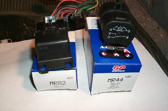
in mike davis web site it says Pin B on the MAF BurnOff Relay and MAF Power Relay, well the relay I have is like the one in the picture and there is no pin B only A, C, D, E, F So Morley What revisions need to be made to make these work Correctly
Diagram also below for camparison.
Code:
Splicing
---------------------------------------------------------------------
C15 splice D15 (Inj 2,4,6,8 "B")(2of2)	D16 (Inj 2,4,6,8 "B") (new D16, old D15)
D16 splice D14 (Inj 1,3,5,7 "A")(2of2)	D15 (Inj 1,3,5,7 "B") (new D15, old D14)

Maf Burnoff relay -  pin A		MAS connector pin D
  and MAF Pwr relay - pin D

Maf Burnoff relay -  pin C		B1 (12V and oil sw override)
  and MAF Burnoff relay - pin E
  and MAF Pwr relay - pin E

MAF Pwr relay - pin A			MAS connector pin F
MAF Pwr relay - pin B			D3 (Ground)
MAF Pwr relay - pin C			B2 (FP signal)


New hookup
----------------------------------------------------------------------
		D12 goes to Maf Burnoff relay - pin B
Senior Member
Joined: Dec 2003
Posts: 623
Likes: 0
From: Point Marion PA.
Car: 1982 CAMARO;
Engine: 1985 LB9;
Transmission: T-5/
Originally posted by MTPFI-MAF
So On a MR44 Relay I would Need to make the changes below Correct Morley.
[/B]
So On a MR44 Relay I would Need to make the changes below Correct Morley.
Code:
Splicing
---------------------------------------------------------------------
C15 splice D15 (Inj 2,4,6,8 "B")(2of2)	D16 (Inj 2,4,6,8 "B") (new D16, old D15)
D16 splice D14 (Inj 1,3,5,7 "A")(2of2)	D15 (Inj 1,3,5,7 "B") (new D15, old D14)

Maf Burnoff relay -  pin A		MAS connector pin D
  and MAF Pwr relay - pin D

Maf Burnoff relay -  pin C  or with a MR44Relay Pin-F		B1 (12V and oil sw override)
  and MAF Burnoff relay - pin E
  and MAF Pwr relay - pin E

MAF Pwr relay - pin A			MAS connector pin F
MAF Pwr relay - pin B or with a MR44 Relay Pin- D			D3 (Ground)
MAF Pwr relay - pin C  or with a MR44Relay Pin - F			B2 (FP signal)


New hookup
----------------------------------------------------------------------
		D12 goes to Maf Burnoff relay - pin B or with a MR44 Relay Pin- D
[/B]
Senior Member
Joined: Dec 2003
Posts: 623
Likes: 0
From: Point Marion PA.
Car: 1982 CAMARO;
Engine: 1985 LB9;
Transmission: T-5/
You Da Man Morley.
I should of been able to figure it out but with making fiberglass shifter plates, Dash Plates, ECM SWAP, ECT. there isn't much brain power left. lol or enough time in a day.
I should of been able to figure it out but with making fiberglass shifter plates, Dash Plates, ECM SWAP, ECT. there isn't much brain power left. lol or enough time in a day.
Supreme Member
Joined: May 2002
Posts: 4,099
Likes: 2
It can get confusing when the relays you get aren't pinned the same as the schematic you are using to wire it up. I had the same problem with my swap and ended up using a battery charger to actuate the relay and an ohm meter to verify which pins did what when it energized.
Senior Member
Joined: Dec 2003
Posts: 623
Likes: 0
From: Point Marion PA.
Car: 1982 CAMARO;
Engine: 1985 LB9;
Transmission: T-5/
Now Morley When I yanked these relays they came from a 90+ car that didn't have MAF and On the Relay Harness Plugs There are some 16ga or 18ga wires and then there are a couple 14ga wires.
My questions.
1. What pins on the Maf Burn Off Relay need to be heavier Guage
2. What pins on the Maf Pwr Relay need to be a heavier Gauge.
Since I have not wired the every thing up yet I can place the Thicker Guage Wires where they need to be. Better Safe than Sorry.
My questions.
1. What pins on the Maf Burn Off Relay need to be heavier Guage
2. What pins on the Maf Pwr Relay need to be a heavier Gauge.
Since I have not wired the every thing up yet I can place the Thicker Guage Wires where they need to be. Better Safe than Sorry.
Supreme Member
Joined: May 2002
Posts: 4,099
Likes: 2
Originally posted by MTPFI-MAF
My questions.
1. What pins on the Maf Burn Off Relay need to be heavier Guage
2. What pins on the Maf Pwr Relay need to be a heavier Gauge.
My questions.
1. What pins on the Maf Burn Off Relay need to be heavier Guage
2. What pins on the Maf Pwr Relay need to be a heavier Gauge.
Senior Member
Joined: Dec 2003
Posts: 623
Likes: 0
From: Point Marion PA.
Car: 1982 CAMARO;
Engine: 1985 LB9;
Transmission: T-5/
Originally posted by Morley
On both relays the heavier guage wire goes to the coil. Pins D&F on the MR 44 and B&C on the other relay.
On both relays the heavier guage wire goes to the coil. Pins D&F on the MR 44 and B&C on the other relay.
Red 12ga on Pin-E
Black Wire with Red Stripe 12ga on Pin-A
But if my thinking is correct the wire comming off of the 85 Mas Module is 16-18ga so as long as all my wires are at least 16-18ga I shouldn't have to worry. Would you agree Morley
EDIT:5/25
Ok Morley I need your assistance again. I went out to my car armed with a jewelers screw driver and was going to attemped to repin my harness to beable to use the 165.
i Insert the jewlers screwdriver into One the upper hole of the harness. (there are 4 rows the 2 middle ones are what the ecm connects to the upper and lower one are where the relese clips are. I think)and i get the first wire to relese and slide almost all the way out of the connector and it catches something again. I tried to get it to come out more but I don't want to damage something so I figured I would Ask.
Last edited by MTPFI-MAF; May 25, 2004 at 12:50 AM.
Supreme Member
Joined: May 2002
Posts: 4,099
Likes: 2
Originally posted by MTPFI-MAF
Hmm Thats Odd. One of the MR44 Relays from the 90+ camaro I pulled is the fan Relay and it has the
Red 12ga on Pin-E
Black Wire with Red Stripe 12ga on Pin-A
But if my thinking is correct the wire comming off of the 85 Mas Module is 16-18ga so as long as all my wires are at least 16-18ga I shouldn't have to worry. Would you agree Morley
EDIT:5/25
Ok Morley I need your assistance again. I went out to my car armed with a jewelers screw driver and was going to attemped to repin my harness to beable to use the 165.
i Insert the jewlers screwdriver into One the upper hole of the harness. (there are 4 rows the 2 middle ones are what the ecm connects to the upper and lower one are where the relese clips are. I think)and i get the first wire to relese and slide almost all the way out of the connector and it catches something again. I tried to get it to come out more but I don't want to damage something so I figured I would Ask.
The wires in the plugs will act like they are sticking just before they come all the way out. If the wire moved more with the screwdriver holding the lock than it does without, then you did indeed unlock the pin. It will take just a little more force to get it out all the way than it did to get it started out (if that makes sense)

TGO Supporter
Joined: Aug 2001
Posts: 1,008
Likes: 0
From: NJ/PA
Car: Yes
Engine: Many
Transmission: Quite a few
Hey, just in case it wasn't clear anywhere(I didn't see it in this thread), the connectors also have a retainer 'comb' looking thing in the back, that helps prevent the pins from falling out, if the tabs would ever fail, so if you are encountering the pins getting stuck, if you didn't take the retainers off, they won't come out. You need to un-clip the small tabs on the corners and the retainers should come right out of the back. Kind of hard to explain, but hopefully, you'll see what I mean, they are usually different color than the connector body(yellow and blue come to mind). Just remember to label the wires, it'll take hours longer to trace them out if you don't. Good Luck!
Senior Member
Joined: Dec 2003
Posts: 623
Likes: 0
From: Point Marion PA.
Car: 1982 CAMARO;
Engine: 1985 LB9;
Transmission: T-5/
yes the retaining comb is off. The wire is like 90 percent out of the connectorthe area where the connector has a strain relief that crimps around the wire is out side off the connector.
Update:5/25 4:37 P.M
I got the wire out that I was Experimenting with but now I can't get it to lock back in. I might of messed the connector that mounts to the wire up, but dosent look like it.
If so is there anywhere to order these connectors.
Update:5/25 5:57 P.M.
I Got the wire to lock in Just before I messed up the The locking tap on the Crimp Connector. I am just going to go to a junk yard and unpinn this wire from a connector and Splice it on the the wire in my car. But at least I figured out how to lock and unlock the tab.
Last edited by MTPFI-MAF; May 25, 2004 at 04:59 PM.
Senior Member
Joined: Dec 2003
Posts: 623
Likes: 0
From: Point Marion PA.
Car: 1982 CAMARO;
Engine: 1985 LB9;
Transmission: T-5/
Originally posted by Morley
Ok, on the MR 44 relay, pins D & F correlate to B & C on the wiring diagram's relay and pins A & E will be the same (this is for the burnoff relay and if it is used for the power relay)
Ok, on the MR 44 relay, pins D & F correlate to B & C on the wiring diagram's relay and pins A & E will be the same (this is for the burnoff relay and if it is used for the power relay)
Code:
:--------------------------------------------------------------------------------
Splicing     Using NEW STYLE RELAY
---------------------------------------------------------------------
C15 splice D15 (Inj 2,4,6,8 "B")(2of2)	D16 (Inj 2,4,6,8 "B") (new D16, old D15)
D16 splice D14 (Inj 1,3,5,7 "A")(2of2)	D15 (Inj 1,3,5,7 "B") (new D15, old D14)

Maf Burnoff relay -  pin A		                        MAS connector pin D
  and MAF Pwr relay - pin D

Maf Burnoff relay -  pin C  or with a MR44Relay Pin-F		B1 (12V and oil sw override)
  and MAF Burnoff relay - pin E
  and MAF Pwr relay - pin E

MAF Pwr relay - pin A			                         MAS connector pin F
MAF Pwr relay - pin B or with a MR44 Relay Pin- D 		D3 (Ground)
MAF Pwr relay - pin C  or with a MR44Relay Pin - F		B2 (FP signal)


New hookup
----------------------------------------------------------------------
		D12 goes to Maf Burnoff relay - pin B or with a MR44 Relay Pin- D
if you do it this way the Maf Pwr Relay New Pin-D goes to D3 Ground & MAS Connector Pin-D
Where in the old relay configuriation Pin B which is the new Pin-D Goes to D3 Ground and There is no other connection. the MAS connection is taken Care of through Maf Power Pin-D
Code:
:--------------------------------------------------------------------------------
Splicing Using Old STYLE RELAYS
---------------------------------------------------------------------
C15 splice D15 (Inj 2,4,6,8 "B")(2of2)	D16 (Inj 2,4,6,8 "B") (new D16, old D15)
D16 splice D14 (Inj 1,3,5,7 "A")(2of2)	D15 (Inj 1,3,5,7 "B") (new D15, old D14)

Maf Burnoff relay -  pin A		MAS connector pin D
  and MAF Pwr relay - pin D

Maf Burnoff relay -  pin C		B1 (12V and oil sw override)
  and MAF Burnoff relay - pin E
  and MAF Pwr relay - pin E

MAF Pwr relay - pin A			MAS connector pin F
MAF Pwr relay - pin B			D3 (Ground)
MAF Pwr relay - pin C			B2 (FP signal)


New hookup
----------------------------------------------------------------------
		D12 goes to Maf Burnoff relay - pin B
Last edited by MTPFI-MAF; May 25, 2004 at 05:06 PM.
Supreme Member
Joined: May 2002
Posts: 4,099
Likes: 2
Don't forget pin D 12 goes to pin B on the MAF burn off.
No matter which relays you use you still have the same number of connections, the only thing that changes are the relay pin letters, still the same number of them just lettered differently.
No matter which relays you use you still have the same number of connections, the only thing that changes are the relay pin letters, still the same number of them just lettered differently.
Senior Member
Joined: Dec 2003
Posts: 623
Likes: 0
From: Point Marion PA.
Car: 1982 CAMARO;
Engine: 1985 LB9;
Transmission: T-5/
Ok update:
Repinning the stock harness is now DONE Start to finish took me about a Hour and a Half. Have yet to Mess with relays. My brain Hurts lol
I think I am probally going to go to a junk yard and get the old 86-89 stlye relay, the one that mike davis uses in his tech article. So all I have to do is wire it according to his directions. The MR44 Relay using diferent letters and Pin configurations is also making my brian Hurt. ( I can't belive that 5 wires in a different configuration is so hard to figure out but that is the way it sems.)
More to come later.
BTW Trickster the diagram helps but the new style relays a confusing me as to what pin coberates with the old style relays pins. Thanks.

TGO Supporter
Joined: Sep 2003
Posts: 6,127
Likes: 12
From: conway, s.c.
Car: 1989 Iroc-Z
Engine: 5.7L TPI
Transmission: 700R4
Hello MTPFI-MAF,
Those relays that you have pictured are the same ones that I have in my car and are the ones depicted in that diagram. The MR44 will be for the MAF Power & MAF Burn-off. The rectangular one on the left (MR82) would be the fuel pump relay.
Those relays that you have pictured are the same ones that I have in my car and are the ones depicted in that diagram. The MR44 will be for the MAF Power & MAF Burn-off. The rectangular one on the left (MR82) would be the fuel pump relay.

Senior Member
Joined: Oct 2003
Posts: 528
Likes: 0
From: NorthEast GA
Car: 85 Trans Am
Engine: 305 TPI
Transmission: 700-R4
Originally posted by Morley
Splicing
---------------------------------------------------------------------
Maf Burnoff relay - pin A MAS connector pin D
and MAF Pwr relay - pin D
Take the wires from pin A on burnoff relay and power relay, solider them together and splice into Pin D on the MAS connector.
Maf Burnoff relay - pin C B1 (12V and oil sw override)
and MAF Burnoff relay - pin E
and MAF Pwr relay - pin E
Burn off relay pins C & E and power realy pin E get spliced together and solidered to an ECM pin you will end up cutting off for splices and put in spot B1
Thank you.
Last edited by ss85tadude; Jun 21, 2004 at 09:15 PM.

Thread
Thread Starter
Forum
Replies
Last Post
LT1Formula
Engine/Drivetrain/Suspension Parts for Sale
20
Nov 14, 2015 12:02 AM
Thomas
Interior Parts for Sale
12
Oct 3, 2015 05:34 PM