When you click on links to various merchants on this site and make a purchase, this can result in this site earning a commission. Affiliate programs and affiliations include, but are not limited to, the eBay Partner Network.
I recently re-wired my whole car. While I was at it I removed the Keyless Entry from it's original mounting location and placed it in a new spot.
It's first spot was under the dash pad, in the center of the housing, It had decent reception - but at times it wouldn't work till I the transmitter was held close to the windshield.
It's been moved to the floor console,.... It's hiding directly under the shifter bezel and the module seems to get better reception in that spot.
To be fair: The keyless hasn't been used in over a year, the FOB battery died and it was just replaced. I don't think that the battery will effect the Modules reception properties since it's powered by the car..... but I don't KNOW that,..... so the new FOB battery is worthy of note.
I wan't to do this already Only thing that keeps me doing this is that I can't find 94-95 camaro/firebird keyless entry module anywhere. I've searched ebay since august. If anyone knows where to get one please inform me. Thanks (No scrapyards here)
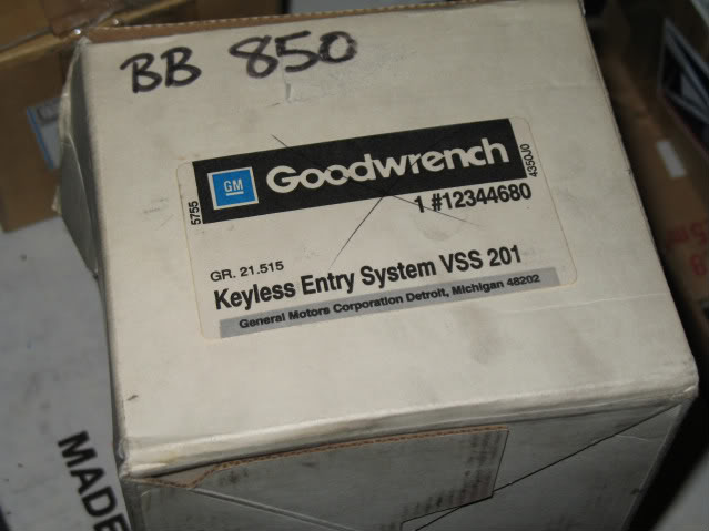
That FOB will work with a receiver that looks like this:
I know it's the 94-95 style...... maybe 96 too but I can't recall.
Oh just what I was afraid of. If only that is acceptable im gonna be sad Impossible to find. Period. Atleast I havent found any while searched over half an year
Here is mine. Its from 94 monte carlo. other output has 4 wires and the other 7. total 11. (mine is abo0116r and OP's is abo0104) as this is 2nd gen RKE module. should be compatible anyway
I got mine and on one plug it has 5 wires which are: black/white, pink, white and 2 light blues. The other plug has 6 wires which are: 2 thick black, 1 thin black, white, tan and orange. Total of 11 wires. I'm trying to figure out what it came out of, becuase it looks like the person was wrong as to what it came from. So I'm not entirely sure what wire is what. This one is also the ABO0116R unit.
Last edited by J. Chris Davis; May 28, 2013 at 11:11 AM.
That's odd. Wonder if you could just put in a higher amp fuse? What is the amp of the fuse you are using now? I wouldn't use more than a 30 amp fuse though either.
Thanks, I will check out that link. A 15 amp would be pretty low. I think the lowest would have been like a 20 or 25. I'm not sure what stock was on these. I would have to look at mine to see what is in there. I'm sure a 25 or 30 would be good.
Thanks, I will check out that link. A 15 amp would be pretty low. I think the lowest would have been like a 20 or 25. I'm not sure what stock was on these. I would have to look at mine to see what is in there. I'm sure a 25 or 30 would be good.
no use even 30A blew up. 20A took two uses before blowing up. At this point I have no idea what is causing this. seems that im the only one experiencing this though
That's strange. Maybe there is a crossed wire or short somewhere? I'm still trying to find what mine came out of becuase it has different wires in different places on its plugs. It will also be a while before mine is hooked up to be able to compare too. Hopefully someone has a good suggestion for you. I wouldn't think it's the unit either.
So I have been trying to match up to what vehicle it came from since the ebay auction listed the incorrect vehicle. Said it was for the 93-94 Monte Carlo. They didn't make them then and I couldn't find anything similar in that year for the wiring. I've been searching and still searching wiring diagrams to see what this was from. it is the ABO0116R unit. if someone can maybe tell me what vehicle it's from or what each wire is exactly. Some of the wires I am not certain on. This is what I have for the plugs.
no use even 30A blew up. 20A took two uses before blowing up. At this point I have no idea what is causing this. seems that im the only one experiencing this though
You should never replace a fuse with a higher rated one than what came from the factory. The point of a fuse is to provide a safe fail point by burning up before your wiring does. You make the fuse a higher tolerance than the wiring and you are asking for a fire.
It's late. I'm very tired. You need to double check everything because I'm in not way responsible for you breaking stuff.
Keyless white - Doorlock relay black (Non-ground)
Keyless black - Doorlock relay black (ground)
Keyless light blue - Doorlock relay light blue
Keyless orange - Doorlock relay orange
Keyless pink - 12v with ign on
That should get you up and running. The first press for the drivers door only is a bit more complicated. The tan on the keyless is grounded normal and flips to positive trigger. Cutting the drivers side tan on the door lock relay, and connecting the actuator side with the keyless tan will definitely have the keyless working right. I don't know if the keyless box sends the 12v through the tan when white is energized. Looking at the diagram you posted from the Fiero site, I'm assuming it does. I don't see any other way the unlock button would trigger the actuator.
The green, blck/white, and black are the hatch release. I wouldn't touch that until you have all the rest working 100%. The other blck/whit is to program. I think that covers all your wires. Post back if you need more help.
All wires are correctly in place. seems that my module is faulty. And my fuse problem has come to point where every fuse breaks right away when it touches the panel. I might get another module in future but for now i'll revert everyhting back like it was.
I will do that for sure. I'll try to get to it as soon as I can. I have a bike project that came before it and I'm trying to get it finished up with it's wiring as well. Electrical, I can't get away from it
Hi, I'm having a hard time to figure this out. I have a 95 keyless entry same as the other listed in this forum. I can not figure out where the 2 wires come from that you have labeled red/black and orange/black. Everything else seems straight forward, I would appreciate any and all help.
I never did get mine installed. Had other stuff come up with the car and now it's in storage for the winter. So I'm not sure on the wiring yet. Hopefully someone has the information you are looking for.
Okay. So I am gonna attempt this. I am wondering how to get the lights to flash when I lock or unlock it. What is the best system for keyless entry? Should I pull one from a 4th gen? Should I buy an aftermarket one? What's the deal.
im trying to wire in one of these 4th gen camaro units into my 90 transam but im not the best with wiring diagrams
my third gen relay has the following wires
blue, 2 greys, orange/black, black, two tans , black
what do i connect to what to make it work
i assume they are spliced into the wires so all existing wires are still connected as well as the new 4 th gen module
not fussy for hatch unlock at the moment or control over each door so long as they lock and unlock
press the fob button and hear the module clicking but doesnt operate locks
same happens if i press the lock/unlock buttons on the door
any ideas
Yikes, my memory isn’t the greatest and I did this project 3 years ago. I wish you were local because it would be way easier to figure out in person. It’s not a complicated circuit or anything but it’s very difficult to troubleshoot these things from a computer screen... You are going to need a test light to figure out what is going on. Start with the basics and make sure you have power everywhere there should be. The fact that your buttons on the doors don’t work makes me think you may have something mixed up. There’s a lot of the same color wires going on so it’s easy for it to happen. See if you have power coming out of the relay. When you use the door buttons NOTHING is going on inside the module. It only travels through the module much like an ordinary wire. Power from the factory relay goes into the red w/black and out the grey to the actuators or into the orange w/black and out the Tans to the actuators. That’s all there is to the door switches.
Test the Orange on the factory relay... That should have 12v.
If that is good, test the tans coming out of the factory relay� They should be a ground unless unlock on the door is pressed. With unlock pressed they are 12v.
If that is good, test the greys coming out of the factory relay� They should be a ground unless lock button on the door is pressed. With lock pressed they are 12v.
Has anyone install a viper 5901 in a 87 trans am? If so do any you his have a wiring diagram or something to help me out? Really would appreciate it. Thanks
I know it's been a while since the last post here but I just found this thread. Has anyone managed to get the door switches to work with the ABO0116R unit? Or is it only possible with the older ones which have multiple internal relays?
Nearly two years later and I haven't gotten mine installed yet. I do finally have the car legal and all other projects done. So hopefully I will be doing this real soon.
Wow, replies... This is how far I managed to get:
Now the trick is to attach the greys and tans with question marks somewhere in the keyless circuit in a way that doesn't immediately send the power to ground when they are used. The difficulty here is that no two diagrams/pinouts for these ABO units agree and none are complete. There are unused terminals and pin A on C1 seems to supply a constant 12V, so it looks as though this must be setup to connect to switches. Why is it that pins A and H on C2 are interchangeable? I have hooked power to one, the other, and both, to find no difference in function. I hope I'm missing something obvious here...
This is pretty straightforward if you don't care about the door switches. Just cut the factory relay out in the above picture.
Nice diagram! Could it be that those two extra wires go individually into the door switches instead of one lead going to two? Or could those be for the shifter when you take it out of park and the doors automatically lock. If they had that option then which I'm not sure on.
Actually those two pairs normally go the actuators on the stock harness, which are cut in this diagram. The factory relay is only used when pressing the switches on the door. I suspect this is going to require 3 more relays, placed between the outputs of the keyless receiver and the actuators. Those relays would allow current to pass through either way by default, then when the current comes from the switch relay, cut that path off and allow only that current through (to prevent shorting). I have some inquiries bouncing around locally, but I guess it's not so bad to have the keyless system and manual locks if it doesn't work out.
Here's my second draft. Just got home and it's late, but this has been bouncing around in my head all day.
With this layout, you lose the standard door lock relay, but pick up a few others. This is relying on the keyless module to act as a ground -- which it will, but is it really a good idea to use its ground when it's not in use? I'm just thinking its internals may not hold up to the abuse. It would sure be nice to know a little more about these units. I would certainly appreciate any feedback or criticism.
Now I'm thinking of adding another relay and diode to power the park lights when unlocked...


 Only thing that keeps me doing this is that I can't find 94-95 camaro/firebird keyless entry module anywhere. I've searched ebay since august. If anyone knows where to get one please inform me. Thanks
  (No scrapyards here)


 Uploaded with ImageShack.us
  Uploaded with ImageShack.us


 I do finally have the car legal and all other projects done. So hopefully I will be doing this real soon.


