
Keyless entry

Junior Member
iTrader: (2)
Joined: Aug 2008
Posts: 39
Likes: 2
From: wausau WI
Car: 1992 25th Anni. camaro
Engine: 5.7 liter ZZ4 swap TPI
Transmission: T56 (manual 6 speed)
Axle/Gears: corp. disc GM 10 bolt, 3:42
Re: Keyless entry
I just got a keyless module out of a 1995 monte carlo just wondering if you ever got this venture to work? and if so a wiring diagram would be greatly appreciated. Thanks


Re: Keyless entry
This is how my ABO0116R module is wired. Everything is working properly with this set up and no extra relays. The module has relays and the factory power door lock system has a relay as well. Didn't feel extra relays were needed. The hatch switch does get triggered when using the remote, but it shouldn't be any different than using the switch itself. Not responsible for anybody's set up, but this is what is working for me.
Module: ABO0116R
Large plug (Black)
A: Orange (12v constant) (added 15 amp fuse)
B: Black (Hatch/Trunk) to brown wire at hatch switch
C: Nothing
D: Tan (Left door unlock) had to cut the tan lead going from the cars relay to the driver lock motor and connected this to it.
E: White (Dome light)
F: Black (Ground)
G: Black (Removed)
H: Nothing
Small plug (Blue)
A: Nothing
B: Pink (12v switched) (added 15 amp fuse)
C: Nothing
D: Light Blue (Lock)
E: White (Unlock Passenger Door) to black unlock lead
F: Nothing
G: Light Blue (Removed)
H: Black with white stripe (Programming)
Last edited by J. Chris Davis; Jul 20, 2016 at 09:07 AM.
Re: Keyless entry
Been doing alot of research and hoping what I have drawn up will work out. I'm going to try to do some testing this weekend. I need to remove a couple of leads from my keyless entry harness above and add one for this to work like I'm thinking.
Member
iTrader: (1)
Joined: Nov 2013
Posts: 443
Likes: 26
From: Switzerland
Car: Red 1991 Firebird with digital dash
Engine: L03 V8 TBI
Transmission: 700 R4
Axle/Gears: 2.73
Re: Keyless entry
Interested. Planning on doing the same.
Are there any diagrams or manuals on the matter?
Are there any diagrams or manuals on the matter?
Re: Keyless entry
Besides the diagrams on here that I have been studying. The only thing I have found close enough to how mine is wired is a 95 Blazer and that has one wire missing from mine and 2 extra the diagram doesn't show. I haven't had a chance to mess with it. I decided to shampoo my carpets yesterday instead and that took all day trying to get stains out.
Member
iTrader: (1)
Joined: Nov 2013
Posts: 443
Likes: 26
From: Switzerland
Car: Red 1991 Firebird with digital dash
Engine: L03 V8 TBI
Transmission: 700 R4
Axle/Gears: 2.73
Re: Keyless entry
Have been tampering around a little today. I've been going through this thread and I have to agree with ynk1121 and John in RI (great thread by the way!)
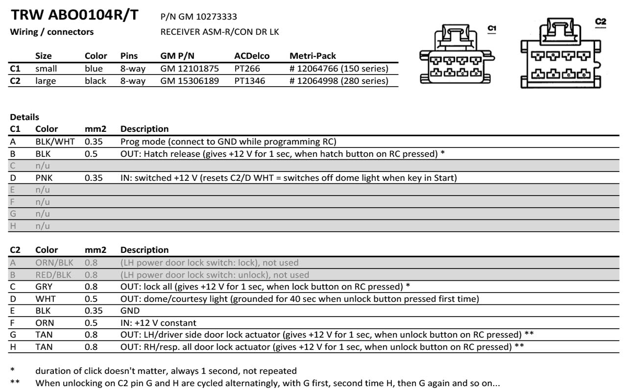
The wire colors and functions match their diagrams. Could it be that you have a different kind of keyless entry system? Or the wrong plugs? The system described here is the TRW ABO0104R.
The wire colors and functions match their diagrams. Could it be that you have a different kind of keyless entry system? Or the wrong plugs? The system described here is the TRW ABO0104R.
Member
iTrader: (1)
Joined: Nov 2013
Posts: 443
Likes: 26
From: Switzerland
Car: Red 1991 Firebird with digital dash
Engine: L03 V8 TBI
Transmission: 700 R4
Axle/Gears: 2.73
Re: Keyless entry
I have collected some data around the web and I found the Pontiac Firebird 4. gen manual 1995. Back then GM used the system described here. I have extracted some of the interesting pages and attached them here.
Here's my diagram, it works well for me, tested it out today.
Here's my diagram, it works well for me, tested it out today.

Re: Keyless entry
I thought I had posted what mine was, but I dont see it. Mine is different it is the the ABO0116R. That's why I'm not able to use their diagrams. I still haven't had time to mess with it yet. I thought I would be able to get the front carpet and floor mats cleaned up this last weekend and that didn't go so well. So been dealing with that still. Hoping to do something with my keyless entry this week or weekend.
Member
iTrader: (1)
Joined: Nov 2013
Posts: 443
Likes: 26
From: Switzerland
Car: Red 1991 Firebird with digital dash
Engine: L03 V8 TBI
Transmission: 700 R4
Axle/Gears: 2.73
Re: Keyless entry
Sorry, I should've been reading more focused. Yes, you mentioned it.
If I come across a diagram I'll post up
If I come across a diagram I'll post up
Re: Keyless entry
I've been looking for a diagram with not much luck with my version. The closest I came up with was a 95 Blazer diagram that had most of the wires in the same location. It had one extra mine didn't and I have 2 extra it does not. Once I get power to it and hopefully a remote programmed I can figure out what the extra leads do. In a few posts back of mine I have how mine is all laid out vs. the 95 Blazer diagram I found.
Re: Keyless entry
I have updated my post 103 with how my module ABO0116R is wired. I have yet to mess with the hatch release and will update that information when I get that part completed. I will also get my wiring diagram I made posted then as well. I have not needed to add any other relays since the car has its own power door lock relay and the module itself is basically a relay.
Last edited by J. Chris Davis; Jul 19, 2016 at 04:13 PM.

Member
iTrader: (1)
Joined: Mar 2008
Posts: 417
Likes: 26
From: Lady Lake, FL
Car: 1988 Camaro
Engine: LR4
Transmission: T5
Axle/Gears: 3.23posi/disc
Re: Keyless entry
Not to bring back a 6 year old thread or anything, but I just went through adding factory keyless entry to my car, and I wanted to add some useful info for anyone who might be going after this in the future. This thread helped me a ton, but also created some confusion as well, so I'd like to point out a thing or two about how I did mine which now works flawlessly after figuring out some things.
1. There are a hand full of different TRW keyless entry modules, from what I can tell they are all wired up slightly differently, but seems like they all use the same connectors(speaking as far as the units that are compatible with the square remotes)
2. The connectors in question are the same posted above.. I got mine through ebay using the Metripack part#'s. Make note that when you buy these connectors that they have 8 wire cavities with only 6 populated, so just know ahead of time you'll need to re-pin some of these wires as well as remove the ones you won't be using.
3. After searching through multiple threads on multiple forums, the only usable info IMO is here.
4. From here on I'll be only talking about the ABO0116R module that I used. It came from a 1995 Caprice. The ABO0116R seems to be the most commonly available used one at this time.
The below quoted info worked almost perfectly for me, but take note of my edits to the quote in bold lettering. Follow the pin lettering from the quote, as it is marked on the connectors themselves.
The way I wired mine in, I believe is the easiest and least intrusive way to do it. From the digging that I've done on this, in its 100% factory form, everything in the power lock wiring goes through this unit.
But for simplicity, I gave it power/switched power/ground/hatch release/dome light ground to trigger the interior lights, that was all self explanatory.
When it came to wiring the lock/unlock function, what I chose to do was use pin D on the large connector to go directly down to the factory door lock relay, using a tie-in splice connector to the black unlock wire that goes from the unlock button on both doors to the relay.
Same thing for the lock wire, I spliced that into the blue lock button wire from pin D on the small connector.
Doing it this way, when you press unlock on your remote, both doors unlock at the same time. Just as when you press lock, both doors lock. You will lose the ability to unlock only the drivers door on the first press, and then the passenger side on the second press.
That wasn't as important to me as much as not hacking up the factory power lock harness. This method also makes it very simple if you ever want to undo this mod. All you'd have to do is simply remove your splice connectors(I've always heard them referred to as "scotch locks") and the wiring/module come right out.
I spent right around $200 for my keyless module, two remotes, and the two pigtail connectors. It took a couple days to get this all installed and sorted out with trying to make sure I was getting the right info and understood it properly.
If I knew then what I know now after actually doing this, I could probably do it in an hour or two. Now I have two OEM remotes and a perfectly working keyless entry system almost as if it came factory with it, almost.
Lastly, I wanted to mention about my note above about wiring the LH unlock and RH unlock wires together that come out of the module. It made sense in my head when I was doing it because I read how the ABO0104R unit alternates 12 volts from left to right with each press of the unlock button on the remote. That may be true for the ABO0104R, but for the ABO0116R, LH unlock wire sends out 12 volts EVERY time you press the remote unlock button, and the RH gets 12 volts EVERY OTHER time.
If you do make the same mistake I did, the module will send 12 volts out continually to the unlock trigger on the relay. The moment I cut the RH unlock wire out of the equation, it works flawlessly. Although I ruined one of my lock actuators in the process of figuring that out...
Once I replace the one burnt out lock actuator, I intend on editing this post with a short video showing how well it works.
I'm not always the best at explaining things, so hopefully this makes sense.
1. There are a hand full of different TRW keyless entry modules, from what I can tell they are all wired up slightly differently, but seems like they all use the same connectors(speaking as far as the units that are compatible with the square remotes)
2. The connectors in question are the same posted above.. I got mine through ebay using the Metripack part#'s. Make note that when you buy these connectors that they have 8 wire cavities with only 6 populated, so just know ahead of time you'll need to re-pin some of these wires as well as remove the ones you won't be using.
C1 - Small GM# 12101875 ACDelco# PT266 Metripack# 12064766
C2 - Large GM# 15306189 ACDelco# PT1346 Metripack# 12064998
C2 - Large GM# 15306189 ACDelco# PT1346 Metripack# 12064998
4. From here on I'll be only talking about the ABO0116R module that I used. It came from a 1995 Caprice. The ABO0116R seems to be the most commonly available used one at this time.
The below quoted info worked almost perfectly for me, but take note of my edits to the quote in bold lettering. Follow the pin lettering from the quote, as it is marked on the connectors themselves.
Module: ABO0116R
Large plug (Black)
A: Orange (12v constant) (added 15 amp fuse)
B: Black (Hatch/Trunk) to brown wire at hatch switch
C: Nothing
D: Tan (Left door unlock) This wire will send 12 volts signal every single time you press the unlock button on your programmed remote. I used only this wire for unlock function.
E: White (Dome light) The easiest way to tie this in, is to splice into one of the wires going to either of your door jamb switches.
F: Black (Ground)
G: Black (Removed)
H: Nothing
Small plug (Blue)
A: Nothing
B: Pink (12v switched) (added 15 amp fuse) Easiest way to wire this would likely be to grab switched ignition from the radio, as it is only for 12 volt signal to turn the dome light off and does not pull any kind of electrical load.
C: Nothing
D: Light Blue (Lock)
E: White (Unlock Passenger Door) to black unlock lead This wire sends 12 volts out on every other press of the unlock button on your remote. DO NOT TIE IT INTO THE OTHER UNLOCK WIRE FROM THIS UNIT! Doing so will result in the modules internal relay to feed 12 volts constantly to the lock actuators/relay until you unplug the unit. (I'll explain below why I advise NOT to use this wire at all)
F: Nothing
G: Light Blue (Removed)
H: Black with white stripe (Programming)
But for simplicity, I gave it power/switched power/ground/hatch release/dome light ground to trigger the interior lights, that was all self explanatory.
When it came to wiring the lock/unlock function, what I chose to do was use pin D on the large connector to go directly down to the factory door lock relay, using a tie-in splice connector to the black unlock wire that goes from the unlock button on both doors to the relay.
Same thing for the lock wire, I spliced that into the blue lock button wire from pin D on the small connector.
Doing it this way, when you press unlock on your remote, both doors unlock at the same time. Just as when you press lock, both doors lock. You will lose the ability to unlock only the drivers door on the first press, and then the passenger side on the second press.
That wasn't as important to me as much as not hacking up the factory power lock harness. This method also makes it very simple if you ever want to undo this mod. All you'd have to do is simply remove your splice connectors(I've always heard them referred to as "scotch locks") and the wiring/module come right out.
I spent right around $200 for my keyless module, two remotes, and the two pigtail connectors. It took a couple days to get this all installed and sorted out with trying to make sure I was getting the right info and understood it properly.
If I knew then what I know now after actually doing this, I could probably do it in an hour or two. Now I have two OEM remotes and a perfectly working keyless entry system almost as if it came factory with it, almost.
Lastly, I wanted to mention about my note above about wiring the LH unlock and RH unlock wires together that come out of the module. It made sense in my head when I was doing it because I read how the ABO0104R unit alternates 12 volts from left to right with each press of the unlock button on the remote. That may be true for the ABO0104R, but for the ABO0116R, LH unlock wire sends out 12 volts EVERY time you press the remote unlock button, and the RH gets 12 volts EVERY OTHER time.
If you do make the same mistake I did, the module will send 12 volts out continually to the unlock trigger on the relay. The moment I cut the RH unlock wire out of the equation, it works flawlessly. Although I ruined one of my lock actuators in the process of figuring that out...
Once I replace the one burnt out lock actuator, I intend on editing this post with a short video showing how well it works.
I'm not always the best at explaining things, so hopefully this makes sense.

Junior Member
iTrader: (2)
Joined: Mar 2011
Posts: 55
Likes: 2
From: Indiana
Car: 1992 T/A Convertible
Engine: LB9 305 TPI
Transmission: Auto
Axle/Gears: 2.73
Re: Keyless entry
Not to bring back a 6 year old thread or anything, but I just went through adding factory keyless entry to my car, and I wanted to add some useful info for anyone who might be going after this in the future. This thread helped me a ton, but also created some confusion as well, so I'd like to point out a thing or two about how I did mine which now works flawlessly after figuring out some things.
1. There are a hand full of different TRW keyless entry modules, from what I can tell they are all wired up slightly differently, but seems like they all use the same connectors(speaking as far as the units that are compatible with the square remotes)
2. The connectors in question are the same posted above.. I got mine through ebay using the Metripack part#'s. Make note that when you buy these connectors that they have 8 wire cavities with only 6 populated, so just know ahead of time you'll need to re-pin some of these wires as well as remove the ones you won't be using.
3. After searching through multiple threads on multiple forums, the only usable info IMO is here.
4. From here on I'll be only talking about the ABO0116R module that I used. It came from a 1995 Caprice. The ABO0116R seems to be the most commonly available used one at this time.
The below quoted info worked almost perfectly for me, but take note of my edits to the quote in bold lettering. Follow the pin lettering from the quote, as it is marked on the connectors themselves.
The way I wired mine in, I believe is the easiest and least intrusive way to do it. From the digging that I've done on this, in its 100% factory form, everything in the power lock wiring goes through this unit.
But for simplicity, I gave it power/switched power/ground/hatch release/dome light ground to trigger the interior lights, that was all self explanatory.
When it came to wiring the lock/unlock function, what I chose to do was use pin D on the large connector to go directly down to the factory door lock relay, using a tie-in splice connector to the black unlock wire that goes from the unlock button on both doors to the relay.
Same thing for the lock wire, I spliced that into the blue lock button wire from pin D on the small connector.
Doing it this way, when you press unlock on your remote, both doors unlock at the same time. Just as when you press lock, both doors lock. You will lose the ability to unlock only the drivers door on the first press, and then the passenger side on the second press.
That wasn't as important to me as much as not hacking up the factory power lock harness. This method also makes it very simple if you ever want to undo this mod. All you'd have to do is simply remove your splice connectors(I've always heard them referred to as "scotch locks") and the wiring/module come right out.
I spent right around $200 for my keyless module, two remotes, and the two pigtail connectors. It took a couple days to get this all installed and sorted out with trying to make sure I was getting the right info and understood it properly.
If I knew then what I know now after actually doing this, I could probably do it in an hour or two. Now I have two OEM remotes and a perfectly working keyless entry system almost as if it came factory with it, almost.
Lastly, I wanted to mention about my note above about wiring the LH unlock and RH unlock wires together that come out of the module. It made sense in my head when I was doing it because I read how the ABO0104R unit alternates 12 volts from left to right with each press of the unlock button on the remote. That may be true for the ABO0104R, but for the ABO0116R, LH unlock wire sends out 12 volts EVERY time you press the remote unlock button, and the RH gets 12 volts EVERY OTHER time.
If you do make the same mistake I did, the module will send 12 volts out continually to the unlock trigger on the relay. The moment I cut the RH unlock wire out of the equation, it works flawlessly. Although I ruined one of my lock actuators in the process of figuring that out...
Once I replace the one burnt out lock actuator, I intend on editing this post with a short video showing how well it works.
I'm not always the best at explaining things, so hopefully this makes sense.
1. There are a hand full of different TRW keyless entry modules, from what I can tell they are all wired up slightly differently, but seems like they all use the same connectors(speaking as far as the units that are compatible with the square remotes)
2. The connectors in question are the same posted above.. I got mine through ebay using the Metripack part#'s. Make note that when you buy these connectors that they have 8 wire cavities with only 6 populated, so just know ahead of time you'll need to re-pin some of these wires as well as remove the ones you won't be using.
3. After searching through multiple threads on multiple forums, the only usable info IMO is here.
4. From here on I'll be only talking about the ABO0116R module that I used. It came from a 1995 Caprice. The ABO0116R seems to be the most commonly available used one at this time.
The below quoted info worked almost perfectly for me, but take note of my edits to the quote in bold lettering. Follow the pin lettering from the quote, as it is marked on the connectors themselves.
The way I wired mine in, I believe is the easiest and least intrusive way to do it. From the digging that I've done on this, in its 100% factory form, everything in the power lock wiring goes through this unit.
But for simplicity, I gave it power/switched power/ground/hatch release/dome light ground to trigger the interior lights, that was all self explanatory.
When it came to wiring the lock/unlock function, what I chose to do was use pin D on the large connector to go directly down to the factory door lock relay, using a tie-in splice connector to the black unlock wire that goes from the unlock button on both doors to the relay.
Same thing for the lock wire, I spliced that into the blue lock button wire from pin D on the small connector.
Doing it this way, when you press unlock on your remote, both doors unlock at the same time. Just as when you press lock, both doors lock. You will lose the ability to unlock only the drivers door on the first press, and then the passenger side on the second press.
That wasn't as important to me as much as not hacking up the factory power lock harness. This method also makes it very simple if you ever want to undo this mod. All you'd have to do is simply remove your splice connectors(I've always heard them referred to as "scotch locks") and the wiring/module come right out.
I spent right around $200 for my keyless module, two remotes, and the two pigtail connectors. It took a couple days to get this all installed and sorted out with trying to make sure I was getting the right info and understood it properly.
If I knew then what I know now after actually doing this, I could probably do it in an hour or two. Now I have two OEM remotes and a perfectly working keyless entry system almost as if it came factory with it, almost.
Lastly, I wanted to mention about my note above about wiring the LH unlock and RH unlock wires together that come out of the module. It made sense in my head when I was doing it because I read how the ABO0104R unit alternates 12 volts from left to right with each press of the unlock button on the remote. That may be true for the ABO0104R, but for the ABO0116R, LH unlock wire sends out 12 volts EVERY time you press the remote unlock button, and the RH gets 12 volts EVERY OTHER time.
If you do make the same mistake I did, the module will send 12 volts out continually to the unlock trigger on the relay. The moment I cut the RH unlock wire out of the equation, it works flawlessly. Although I ruined one of my lock actuators in the process of figuring that out...
Once I replace the one burnt out lock actuator, I intend on editing this post with a short video showing how well it works.
I'm not always the best at explaining things, so hopefully this makes sense.

Member


Joined: Jul 2021
Posts: 127
Likes: 38
From: Western WA
Car: 1989 Firebird
Engine: 2.8 V6
Transmission: T-5
Re: Keyless entry
I know this is digging up an old one, but what gauge wiring did everyone use to put this in? Would 18 for the Grey/Tan be enough, 20 for everything else? Or should I step all of that up?

Thread
Thread Starter
Forum
Replies
Last Post
thefirebirdm@n
South Central Region
3
Sep 14, 2015 01:45 PM
BlackphantomZ28
Engine/Drivetrain/Suspension Parts for Sale
0
Aug 22, 2015 01:00 PM
S92RS
Electronics
3
Nov 6, 2000 11:05 PM