When you click on links to various merchants on this site and make a purchase, this can result in this site earning a commission. Affiliate programs and affiliations include, but are not limited to, the eBay Partner Network.
So you can use a factory type Digital Ratio Adapter Controller (vss buffer) to account for dfiferent gear ratios. This is how GM did it, actually.
Problem is, all the websites that discuss modifying GM dracs show a bank of connections that can be adjusted as necessary in a sort of binary fashion to account for a whole range of signal multipliers/dividers. The one in my car does not have such a bank.
This is the wire output on these, I believe:
So, basically, in theory I can preserve the factory wiring and just recalibrate my VSS buffer, but the problem is that the more complex ones that can be reprogrammed dont seem to be the same type of device.
To further complicate things, as far as I know, only the TBI cars got these things. Maybe the TPI cars got something similar to the more complex ones?
So the option is to buy an SGI-5 box to get my speedometer working, or I can buy one of these modules off ebay for $30-$50 and tweak the pin array to get my multiplier correct. But what exactly happens to the VSS buffer box I have if I install an SGI-5 box? Does it replace it? Or does it piggy back on it?
This is a carbureted car, I dont need the ecm to care or know how fast the car is going since the ECM no longer exists. All I need is to get my pulses per mile into a range where my speedometer is happy.
Anyone with a more in depth knowledge of electronics have anything they can add?
This is another wiring diagram for these, but it doesnt seem to jive much with the above one(which is the same as the one I have).
These things arent terribly cheap on ebay, but they're a little cheaper than the SGI-5 boxes. Just wondering if I can do this more elegantly.
The first picture I uploaded is a MODIFIED AFTERMARKET one, that uses a dip switch array in place of connections that you could put on yourself. But you can easily do that yourself as well, thought you guys might be curious about that. The second is the one that was in my car, and the pdf file is a detailed write up on how to find your ideal switch combination and how to modify your drac for different wheel/tire combos.
The VSS Buffer Box looks to be a simple amplifier which takes the signal from the VSS and outputs it to the various accessories (ecu, speedo and cruise control). You can't run all those accessories from the VSS directly as that much load would kill the signal. The Bufffer Box simply provides the power to run those things. The DRAC on the other hand looks to have the electronics to modify the incoming signal frequency to alternate frequencies via the jumper settings. Could you use the DRAC in place of your VSS Buffer Box? Probably. The only caveat would be the VSS itself, it would have to be compatible with the DRAC (ac output vs. digital pulses). If you look at the pc board for the Buffer Box, you will see the diode on the input from the VSS. That diode simply half wave rectifies the ac signal from the VSS, creating a pseudo digital pulse train. The output from both the Buffer Box and the DRAC are digital pulses so they should be compatible there. HTH!
That explains a lot.... I wish I knew more about this sort of thing, but if the board above is just a signal amplifier... I wonder how GM accounts for different gear ratios in the TBI cars. Maybe they ALL got 2.73s?
Yes, TBI cars got the VSS buffer box. MAF TPI and Q-jet cars with elec. speedos also got them. It's not a DRAC though.
Like big al said, yours is simple and passed through a 4 pulse/rpm signal (to all elec. speedos in third gen. and some cruise modules), or divides it to 2 pulse/rpm (for MAF TPI ECMS, TBI ECMs, some cruise modules,)
Trucks with 40 tooth reluctor style VSS (around 88?) used the DRAC box with dip switches and much higher resolution change capability so they could accommodate a lot more gear ratios, tire sizes, ECM styles and transmission options. The wiring for them won't match the VSS buffer box but they can be used in place of it with wiring changes.
In your car, the only thing that needs changed is the signal between trans. VSS and VSS buffer box. Saying it's carbureted and overmodifying things wouldn't accomplish anything positive, and would just make it tougher on a possible use of cruise or ECM in the future. In this case, be lazy and modify only the one signal; it's all that needs done. Here, he lists the wiring he did to only mod. the one circuit: https://www.thirdgen.org/forums/tran...-mismatch.html
I've seen a small motorcycle speedometer calibrator on eBay that would probably do it. Someone here posted a speedo ratio adapter from AU that was affordable (https://www.thirdgen.org/forums/memb...g-project.html post 27) Or the SGI-5 will do just fine modifying only the one VSS circuit.
I didnt think the cars with electronic gauges and a vss even had changeable speedo gears?
Yup - All electric speedo cars had speedo gears. ( FYI: Thirdgen Electric Speedo gears are NOT the same as Cable VSS Speedo gears ! )
Originally Posted by InfernalVortex
Given how far off the T56 vss is from stock... looks like thats not really an option
T56 wasn't mentioned in earlier posts,.... I thought you were asking about the stock VSS/Buffer in a stock TBI car.
In My Case; spending a few $$ on the SG-5 was well worth not wasting any time/effort trying to "re-invent the wheel". My 84 ( factory carb/Auto ) had a electric Speedo VSS Buffer. When I installed a T56 I retained the T56 VSS & simply removed the factory buffer and installed the D/D SG-5 signal converter in it's place,......... DONE.
Yup - All electric speedo cars had speedo gears. ( FYI: Thirdgen Electric Speedo gears are NOT the same as Cable VSS Speedo gears ! )
T56 wasn't mentioned in earlier posts,.... I thought you were asking about the stock VSS/Buffer in a stock TBI car.
In My Case; spending a few $$ on the SG-5 was well worth not wasting any time/effort trying to "re-invent the wheel". My 84 ( factory carb/Auto ) had a electric Speedo VSS Buffer. When I installed a T56 I retained the T56 VSS & simply removed the factory buffer and installed the D/D SG-5 signal converter in it's place,......... DONE.
I understand that.
The problem is the battery is dead on my NVSRAM, so it's reverting to my backup prom which has the VATS enabled.
I have a carbed sbc with a t56. I bought the sgi5 and it worked great. And it has + - buttons on it so you can dial in the speed while you drive. I also like that it looks like I could use it on any combination I ever want to put in the car.
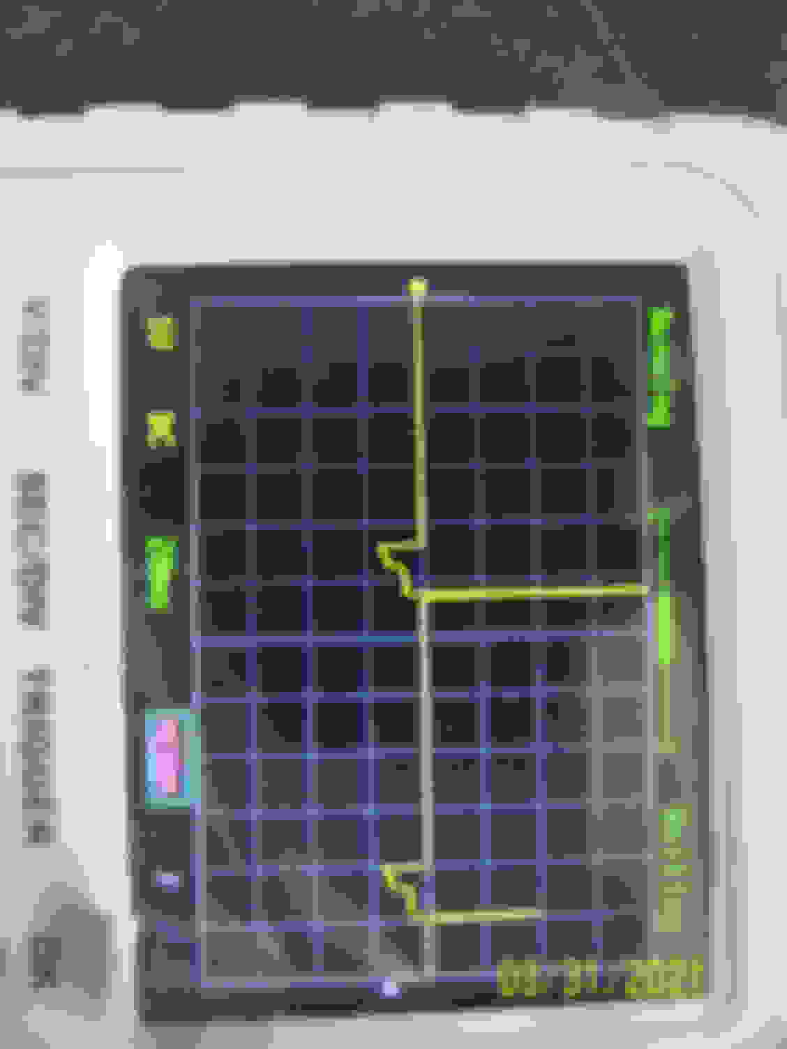
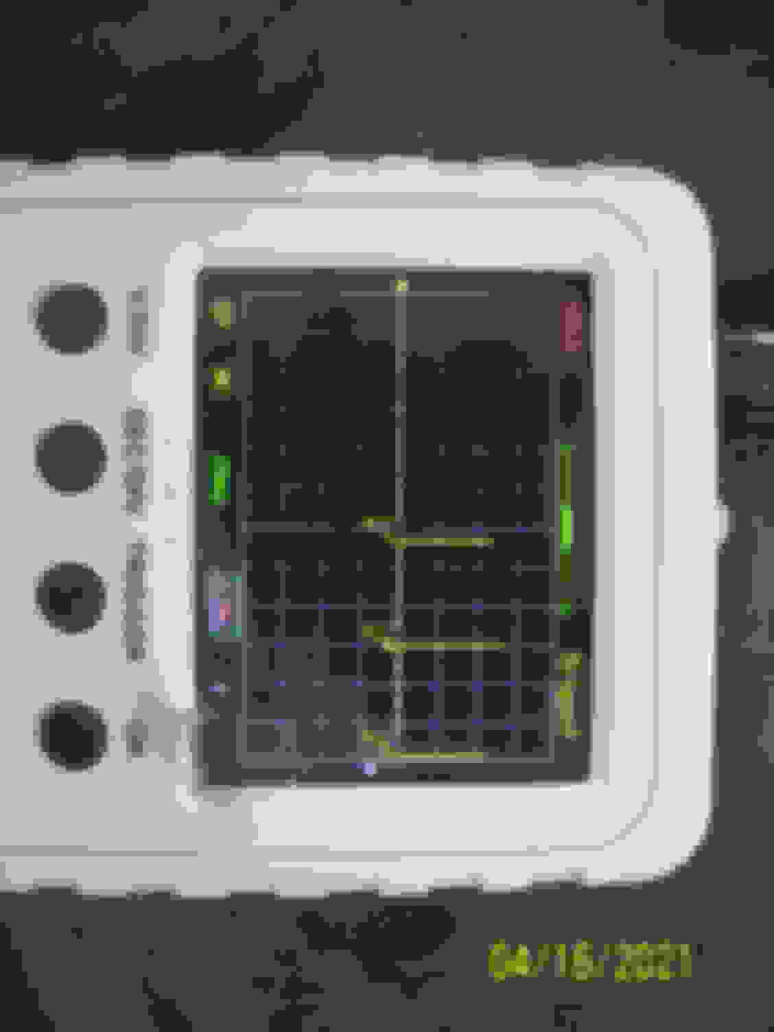
This is a great thread with a lot of useful info. I'm not aware of another place where with HEI output waveforms posted. I was more interested in this from a trouble shooting standpoint vs performance. I have a '82 454 Chevy that had a bad HEI module (that died while the engine was running and then wouldn't allow the engine to start) . It was difficult (for me) to diagnose because it would blink a test light, give a tach rpm reading, and fire a wide spark plug gap in open air, all while under cranking. I've attached some pics below (10x probe on Tach signal, scope grounded to Batt wire). I don't have a classic analog scope as used above, but I have a el-cheapo DSO digital pocket oscilloscope, that does give some facsimile of the ICM output wave form. I've attached pics comparing the output of the bad ICM (which failed the "energy" test @ the auto parts store btw) to the working replacement (AC Delco) ICM. The major difference I see is the negative going square wave on the initial dwell is shorter for the new module vs the old one (this is during engine cranking). I initially would think it would be the opposite, unless the bad module cant current limit as well as the new one? Again, I'm trying to establish a repeatable home/roadside test method to determine if the ICM is bad in the future. Any inputs welcome Engine cranking, bad ICM, 10x probe, 10V /division ICM output, engine cranking , good ICM (ignition working) 10x probe, 10V /div