When you click on links to various merchants on this site and make a purchase, this can result in this site earning a commission. Affiliate programs and affiliations include, but are not limited to, the eBay Partner Network.
LTX and LSXPutting LT1s, LS1s, and their variants into Third Gens is becoming more popular. This board is for those who are doing and have done the swaps so they can discuss all of their technical aspects including repairs, swap info, and performance upgrades.
I have a question on the VSS buffer box for a LS swap. I know that the buffer box (yellow box behind the passenger side dash panel) is not needed and needs to be bypassed. I do not know how, which wires need to be connected.
I believe this is what I have:
I seem to be unable to start the car without grounding the ground wire in that circuit, and I currently have no Speedometer or Tach working. Do these wires need a jumper on them?
It also looks like I could use the pnk/blk wire for a boost wire on the speedometer if need be.
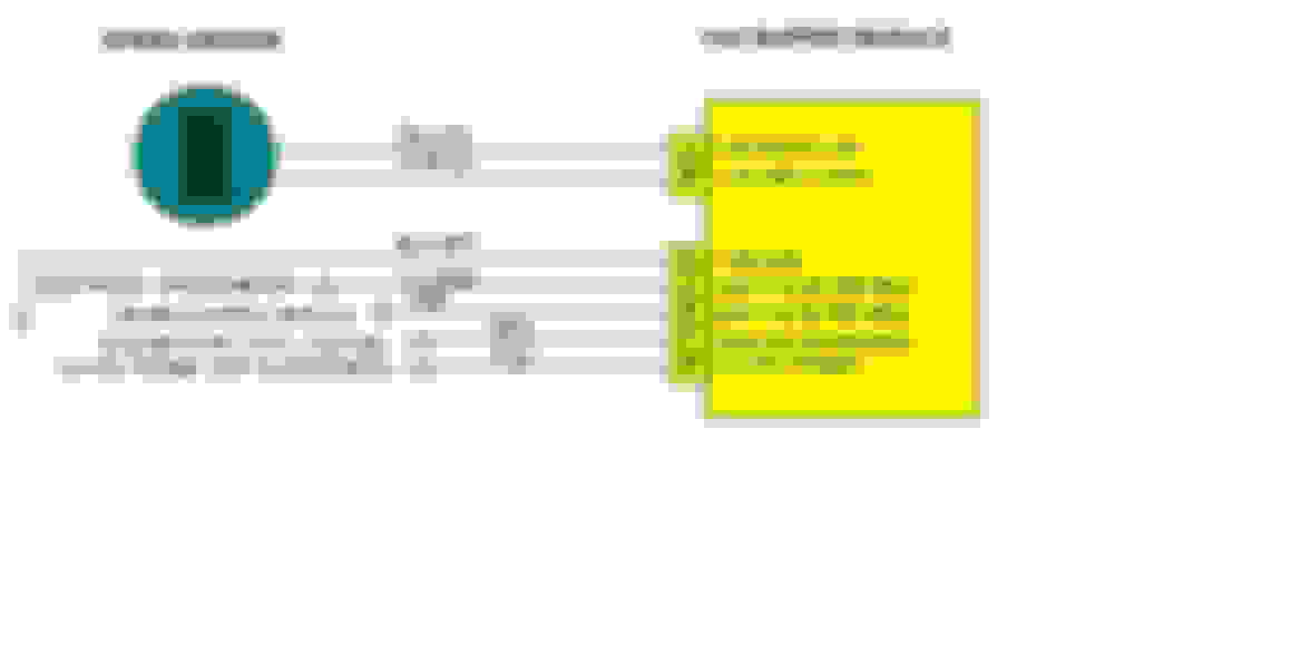
I haven't actually done this so you might take my advice with caution, but I also have a 1989 Firebird so I had to research it. My understanding is that you already have an electronic speedo that can understand the speed output of the LS1 PCM. You don't even need the buffer box any more. The goal is to get the speed signal from "R50" of the LS1 PCM to your speedometer input, which is "pin C" of the connector at VSS buffer box.
* You can do it directly
OR
* You can tie LS1 PCM "R50" to the C207 connector pin K, and then jump pins C and F at the connector for the VSS buffer box. Most people do it this way because they have other connections at C207 anyway and it is a more tidy layout.
That's probably what I need to do. I forgot the box was removed at some point, and the connector was stuffed behind the dash. I reached back there looking for loose wires and pulled that connector out going "well that's probably why it doesn't work!
I know on the LT1 (looks like the same on LS1) the VSS goes directly into the ECM and there is an output for the speedometer. No box required. You only need a box (SGI-5) when you're using the wrong VSS signal.. IE a T5 where the ECM wants the 4L60E/T56, and only because the VSS generated is completely different than what the computer expects. If you're using cruise then there's an output for that too.
As for the ground, there is a wire on that side if memory serves that you ground to kinda bypass the VATS.. I'm running MegaSquirt so I grounded it, but I think on the LT1 (likely same on LS1) there is actually an input for it. So that may be why it won't start without grounding it. Assuming when you say it won't start, you mean no crank and even the relays aren't picking up.
You can bypass PASSkey (what people call VATS) one of three ways.
1. Keep the PASSkey module and install a resistor, that matches the key, across the two key switch wires located under the steering column. The PASSkey will always see the correct resistance and let the engine start.
2. Remove the PASSkey module and jump terminals A3 and B1 at the PASSkey connector. This will energize the start relay whenever the key switch is in crank position and let the engine start.
3. Eliminate both the PASSkey module and the start relay. The relay is located on the driver side kick panel. Unplug the relay permanently and jump the large purple and yellow wires. The wires will be energized whenever the key switch is in the crank position. All the relay and PASSkey wiring is not needed.
Well I got the car started by grounding the blk/wht wire from the VSS connector. This appears to be a common ground used in several other circuits from my reading. I also connected C and F as well. I haven't been able to try it out again, but at least the car starts now. I still have to figure out the tach though, this is using a harness Pocket built for me so it is very much plug and play. However, I don't know if I will still need to boost circuit tied into the tach feed to get it to work. Setting the tach to 4/6/8 doesn't seem to matter in HPtuners.
* You can tie LS1 PCM "R50" to the C207 connector pin K, and then jump pins C and F at the connector for the VSS buffer box. Most people do it this way because they have other connections at C207 anyway and it is a more tidy layout.
Thanks to dimented24x7 post #17 and 18. Purchased a 1985 Z28 with bad tach. Followed the instructions and pictures. Snipped Pin #4 and #10 at the white IC chip. I traced the PCB back to where Pin #4 and Pin#10 went. They were in the upper left corner of the PCB within a half inch of each other. I took a 1/64" drill bit and drill a hole right on each solder point in the upper left corner. I put two 100K ohm resistors in series, put the leads through the two holes and soldered. Checked circuits for continuity from solder points back to the original IC leads at #4 & #10. Popped the tack back in and it works perfectly. My car is a 305 TPI. Thanks!
Thanks to dimented24x7 post #17 and 18. Purchased a 1985 Z28 with bad tach. Followed the instructions and pictures. Snipped Pin #4 and #10 at the white IC chip. I traced the PCB back to where Pin #4 and Pin#10 went. They were in the upper left corner of the PCB within a half inch of each other. I took a 1/64" drill bit and drill a hole right on each solder point in the upper left corner. I put two 100K ohm resistors in series, put the leads through the two holes and soldered. Checked circuits for continuity from solder points back to the original IC leads at #4 & #10. Popped the tack back in and it works perfectly. My car is a 305 TPI. Thanks!