When you click on links to various merchants on this site and make a purchase, this can result in this site earning a commission. Affiliate programs and affiliations include, but are not limited to, the eBay Partner Network.
hey guys forgive me if this has been answered already. i have the 87 z28 with a 305 carb, originally rochester cc but now non cc.
i believe it is the oil sending unit, two wires, orange and brown. from the sending unit where do these wires need to run out to for proper functioning?
TunedPerformance, I have the mechanical pump on the pass. side block. I have read there may/may not be a "booster" electric pump in the tank. So I am not sure if it's got one... If so, and because the computer has been removed would that pump be functional or is the mechanical pump sucking fuel through it? What does the sending unit have to do with the fuel pump and otherwise what is its function? Sorry for the stupid questions but this is where I get confused. Any help would be appreciated. Thanks guys
Power for the tank fuel pump is routed through that oil pressure switch to ensure that the engine is running before pumping fuel. It's done for safety.
Ok i think i've got it, reading into it more and more. Can be confusing with all the different models, etc. Thanks for the help guys. Need this rain to hold up before I can tear into it.
Yes it's got three wires, Black, Grey and Tan/White
When this car was swapped to a non cc carb setup, a lot of the wires were just cut and tied back. So in an attempt to clean up some of that mess, I pulled out the ECU and associated harness (Pics 1 and 2), but in doing so I think I removed a harness that should have stayed. I have separated that harness (Pic 3) and think I need to plug it back in. If this is correct then I need help running the wires out:
Orange from harness Y's to Oil pressure switch and fuel pump relay
Purple/White from harness to fuel pump relay
Then I see in the diagram the Tan/White is Y'ed from the oil pressure switch and the relay and goes to fuel tank unit but how is it tied to the harness? What wires do I need to run out to get this hooked up correctly?
To keep the pump relay you would need to ground the black/white wire and use a switched power like ignition coil power to control the relay.
The relay would give you a pump prime if you turn the key to the on position and would run as long as the engines running eliminating the oil pressure switch. Or you can use the oil pressure switch to power the pump and ditch the relay. I don't think you really need a prime since there is fuel in the carb bowl.
So The only place I can find corresponding wires to the Oil Pressure Sensor pigtail (pic 1) is on what you are calling the "pass through connector" for ecm wiring (pic 2). I have dug through C100 and cannot find anything that matches the Oil Pressure Sensor (pic 1). C100 Does, however, have the pigtail for the Fuel pump relay (pic 3).
If I plug the "pass through connector" back in under the dash, run the Orange and Brown wire to the oil pressure sensor pigtail, plug the OPS in, and then plug my fuel pump relay back in over by the brake booster, would this be correct? Just need a verification here.
"Pic 2" of previous post ("pass through connector") has been separated from the big ECM harness (see pic attached to this post). This Plug DID NOT Plug into my ECM, rather into separate plugs under the dash. This is the harness I am referring to when I say "plug back in and run out to OPS"
Thanks again for the help so far TunedPerformance. Also thanks for Identifying harness as C207. If anyone else wants to chime in I could sure use the help.
So I think in Post # 12 I was getting pretty close. Brn/Wht and Org (both heavy gauge) from C207 tie directly to OPS plug.
However when I refer to the "Pigtail for Fuel Pump Relay (from C100 - Pic 3 of Post # 12)" - That Pigtail is infact for the Fan Relay (4 prong). The plug for the fuel pump relay (missing) comes from C207.
Could somebody verify this? Or alternately does somebody know where I could find a C207 Pinout Diagram for 87 305 CCC? Thinking If I wire up OPS plug and Fuel Pump Relay from C207 then I should be in good shape?
That I would have to check tomorrow when I have some daylight. To the best of my knowledge C100 hasn't been tampered with. If I even had the plug for the fuel pump relay (so I knew the colors) I could almost say without a doubt if it went to c207. I was unable to find a Diagram for a 1987 LG4 Vin H. Some of the colors are similar so it would be nice to go by the letters (A thru R)
I need to know - Or see a picture of - wire colors for fuel pump relay plug on an 87 lg4 vin h 305 carb. Hopefully someone with this model can help me out!
Pretty sure my answer lies in c207. Auto parts store has a plug but all 5 wires are white.
also tunedperformance I'll check c100 tonight when I get home but 95 percent sure it hasn't been messed with.
Last edited by baker440ex; May 31, 2017 at 08:27 PM.
Thanks for the help TunedPerformance. And thanks for chiming in DeadBird. Was nice when I got home so I put the battery in and got the test light out.
On C207, Pin D (Blk/Org to Org) is hot at all times. Pin F (Pink/Blk) was hot with key on, and Pin P (Ppl) was hot with key on...
The schematics say Ppl/Wht (Crank fuse 3 amp) should be hot at all times. My Ppl/Wht wire is pin J and that was not hot. (Do I need to crank the motor? Cause I didn't)
According to Tuned's link to C207 connector pinout, pin L (tan/wht) is fuel tank to fuel pump relay and pin M (blk/wht) is a ground. These pin letters do match the colors I have on my connector.
The only other thing...Both schematics (TunedPerformance and DeadBird) show a 4 pin relay. I picked one up at the parts store which has 5 pins. So I'm a little confused there...Did I get the wrong relay?
Other than that from what I can tell I need to use Pin D, Pin J, Pin L and pin M from C207. Am I on the right track here?
Last edited by baker440ex; May 31, 2017 at 08:30 PM.
The fifth terminal (87a, for a bosch relay) went to the G terminal on the ALDL plug under the dash. Jumping +12v to the 'G' terminal would power the fuel pump (as a test, I suppose ?)
The 'crank' fuse is , just as a TPI, hot only during crank. Apparently after that, the fuel pump relies solely on the OPS (oil press. switch) to power the in tank pump.
Your 'A" circuit needs to correlate to terminal #1 (switched on when relay is powered)
Given the chance to redo the OE wiring, I, personally, would probably rewire the OPS to be inline to the 'crank' circuit so the OPS energizes the 'crank' side of the relay coil, +12v side, to make the relay be the primary switch to be the power source to the in tank fuel pump. JMO though... (if none of that makes sense, just disregard... lol)
Ok I just went ahead and gave it a try. Picked my connector up today. So in the pic I drew of the connector, the relay is actually backwards, so it would go E,D,C,B,A... Anyways I had my carb off and a couple other things but it fired right up after a couple tries (bowl and line were empty)
So how do I know if my pump is working? So I know the mechanical is not just sucking fuel through a dead pump....
I'll take a stab at this.
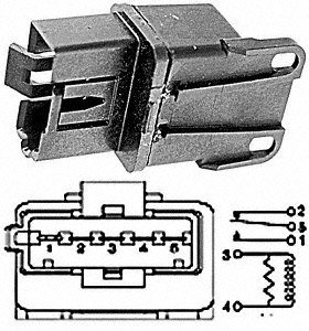
On the picture of the relay you bought, (forget the ABCDE)
1 is the normally open (NO) contact - connect to your tank fuel pump TAN/Wht
2 is the normally closed contact (NC) - not used
3 is one side of the relay's coil - connect to Ground BLK/Wht
4 is the other side of the relay's coil - connect to Crank PPL/Wht
5 is the relay's movable contact - connect to ORN (Hot, +12v)
The FP oil pressure switch is wired across the relay's contacts to keep the fuel pump
energized as long as the engine has oil pressure. Connect as shown on your diagram, if it is not already.
Google searched for jd191j6 relay - images.
I found this:
So the answer is:
A is 5
B is 4
C is 3
D is 2
E is 1
Therefore, E 1 is the normally open (NO) contact - connect to your tank fuel pump TAN/Wht D 2 is the normally closed contact (NC) - not used C 3 is one side of the relay's coil - connect to Ground BLK/Wht B 4 is the other side of the relay's coil - connect to Crank PPL/Wht A 5 is the relay's movable contact - connect to ORN (Hot, +12v)
Last edited by NoEmissions84TA; Jun 3, 2017 at 10:02 PM.
Not that I can see. The relay's coil should have energized if you cranked the engine. But the contacts were not properly connected, so +12v had no where to go.
Wait, now I'm confused. Actually it would work wired the way you had it.
But the correct way to match the GM wiring diagram is below.
Attached IS correct.
If you want to see if your fuel pump runs, touch the orange wire to the tan/wht.
Or if the wires are properly connected to the relay's connector, you jumper A to E, which is exactly what the relay does for you when you crank the engine. Then once the fuel pump oil pressure switch is made (engine runs), that keeps your fuel pump running. It is wired this way for safety - should your engine lose oil pressure, then power to the fuel pump is killed.
This is the diagram you want to follow. Good luck.
Edit: funny, I just noticed the letters on the GM diagram - A (tan/wht) fuel pump, B (blk/wht) ground, C (ppl/wht) Crank, E (ORN) +12v. It matches exactly what I came up with.
Last edited by NoEmissions84TA; Jun 4, 2017 at 10:18 PM.
Correct:
A 5 Orange
B 4 Ppl/Wht
C 3 Blk / Wht
D 2 Not Used
E 1 Tan / Wht
How it's Wired:
A 1 Tan/Wht
B 3 Blk/Wht
C 4 Ppl/Wht
D 2 Not Used
E 5 Org
Going to switch it around now. Would that have done any damage the way it was?
So I had it right the first time? Ive ran the car both ways now, seems to be the same. I unplugged it and it started up and ran. Which is the correct pattern?
You didn't have it entirely correct the first time. But the pump should have run. Follow post #36. See the attached picture. This will match the GM diagram.
No emissions, in post #36 you have conflicting information.
The GM diagram you supplied reads different from the thumbnail you attached. Since I have wired it both ways I just want to verify which one is correct.
Is the replacement relay the same or different from the factory relay?
By the way I just jumped the pump like you said and it does work. Side note when I first pulled the line it just kept flowing and flowing. I had to elevate it to get it to stop. Siphon?
Last edited by baker440ex; Jun 8, 2017 at 04:29 PM.