When you click on links to various merchants on this site and make a purchase, this can result in this site earning a commission. Affiliate programs and affiliations include, but are not limited to, the eBay Partner Network.
Looking for any information on "circuit board schematic diagrams" for a either 1984 85 or 86 Berlinetta with digital instrument cluster.
Any help would be greatly appreciated.
I do know the 8s and 6s are different but didn't realize one of the three 3rd gen production years was unique. I do happen to have the instrument cluster pinout already, but do thank you for your help.
Trying to find any info on restoration and repair on Berlinetta digital gauges / instrument clusters aside from reproduction is nearly impossible, let alone finding factory circuit board schematics.
Even finding images of the screen printed circuitry to gain reference points would be helpful. Specifically the "TOP" display board with the florescent speedo and tach.
There is supposed to be 2 different V6 clusters: one for LC1 ( RPM bar graph tach begins to flash @5200 ) and the other one was used in LL1 cars ( RPM bar graph tach begins to flash @5500 ). I've never seen a LL1 Berlinetta ( V6 "HO") but it might be real.
Someone has done some custom work to that cluster,.. the wiring on the upper right is not stock.
The cluster pin schematic I posted is for the 84,.... pretty sure that the wiring to the cluster changed a little starting in 85 when the face-plate was re-designed.
Most clusters die because of problems to the middle circuit board. Most common failure is no digital readout of any kind or no SYSTEM MONITOR function. ( and a combination of both problems. ) This is not the only place these problems can arise from - but by-far the most common. Most gauge and lighting problems trace back the the printed circuit.
If you've got that part of the cluster,..... isn't that what your lookin' for ??
Thanks for the info. I didn�t realize there were so many variations.Sorry� my bad. I should have been a bit more specific and at least posted my specs.This is for a 1984 Camaro Berlinetta Coupe 5.0L 305.2 V-8 automatic.Yes, the top board was toast when I got it. I did the repair work on the board myself. Nothing worked in the instrument panel except the right turn signal. That was a pod issue.I managed to get it from �dead� to �EVERYTHING� lighting up at once in the KOEO position, so I was thinking it has to have some life left in it. Yes, I posted the pic to show what I�m talking about.Even finding a scorch free reference to look at would be nice, but so far nothing out there.
I've got several of these,........ what exactly do you need to see that you can't see on your own pack of circuit boards ??
Do you KNOW FOR SURE what year/engine that cluster board pack in your picture was taken from ??
FYI: The cluster internals are NOT all the same from 84-86. The "middle" board and the "back" board have obvious physical changes made to them and must be used with each other. ( one 'set' fit properly together, the other 'set' fits properly together,.... a mix of boards from each of the 2 'sets' will not fit together.)
Pretty sure that the "display" boards are compatible with both 'sets' of the other 2 circuits boards - but it's possible/likely that the display board was changed too. There's different #'s recorded at the top right of the display boards; don't know if this is just due to V6 vs. V8,... or if there is more to it than that.
Edit: What was the problem that you fixed on the display board ??
Last edited by John in RI; Jun 28, 2018 at 11:06 AM.
Reason: Edit:
Wow you have several? That is amazing. Hopelufly the pix will show up well enough. Well, I can�t be certain if it is original to the car as was from production. But did take it out of this 84. I was wondering if the markings at the top right would lead me to any info but no luck.I�m sure your right do to the two different engines/speed sensors/tach etc.Ok... Circled in the �green area� is the portion of the top board I need to see for reference.
It cooked 4 of the pins so they were replaced by the high strand count routed wiring you see.
I moved some of the wiring aside for a better detailed shot of the mortar hole.
One detailed shot is of the top side of the top display board and the other detailed close up shot is the bottom side of the top display board.
I also included a side shot of the entire tri-layer. top of top display circuit board bottom of top display curcuit board side view of Tri-layer digital display cluster circuit board
Thank you so much for all your time. Very much appreciated.
OUCH ! If I could only count the number of clusters I've seen like that !!!
Here's a couple pics that might help.....
Side view:
Straight down view:
back of the "display" board:
back of the "middle" board:
If you "right click" on a picture, COPY the web-link / image address, PASTE the web-link into your browser, then press ENTER,....... you will see the full sized images.
Sweet! I am shocked at the help I am getting here. OUTSTANDING!!!
The pix are exactally what I was hoping for. Thank you thank you thank you....
Interesting! So do the majority of these blow out at the same points.
2 Questions... I am going with a high strand count for all the circuitry wiring.
Do you agree or do you recommend different materials?
Its my belief that low strand counts fatigue much sooner than high strand counts under normal vibrations.
Also.. I'm using 50/50 solder. 50% tin 50% lead. is this ok or should I go with a higher tin count?
I will post my results after my attempts of repair are made.
You da Man John! Thanks a TON!
Hi John, Thank you again so much for the information I needed in order to route the wiring in place of the 4 burnt out posts and circuitry for the display board. The instrument panel board was fried when I bought it. My first attempt to wire the burnt circuitry “prior to your help”, EVERYTHING lit up. MPH Display read d88 Odometer read 88888.8Now that I’ve rerouted the circuitry back to their correct pathways via hardwiring
and plugged it back in to the cluster harness in dash, the display did not light up but all warning indicator lights lit up constant.The high beam indicator now works and now the L and R turn indicators/hazards work. Rewire from using reference exampleI would like to find specifications for doing a bench test on this instrument cluster. Not sure if pin C-14 is 5V or 12V using chassis ground pins D7 and D8? I have IP cluster harness checks list as well as both output input cluster diagrams but not sure about the 5V signal at PIN C-14 “speed”. Bewilderfied
No Problem; I always like to help where/when I can !!
You might have repaired the obvious melted wiring,... but how can you tell what components on the board were fried when that circuit board was on fire ?? I honestly don't know how to tell. Without detailed circuit board schematics the only way to know what/where the various circuit board traces lead to 'by eye' is about the only way I think of to begin trying to figure out the boards issues. Once you know where and what the traces lead to,... I'm guessing that you could figure out a way to test at least some of those components.
The High Beam indicator is a "stand alone" indicator. It should function normally even when the digital sections of the dash ( & / or the SYSTEMS MONITOR ) are dead. The same is true for the Directional (blinker) arrow indicators all the other tell-tale warning lights that are not included in the SYSTEM MONITOR section of the cluster.
When I bench test a cluster, I plug it into a know good set-up. If the cluster works - great,..... if it doesn't work it goes into the junk/parts pile. Most warning lights can be activated or checked by applying/removing ground, and when a distributor and a VSS are connected the Tach and the speed display will work if the cluster is OK.
The wiring and solder your using should be fine. I use 50/50 solder for most electronics I dare to screw with.
The 'IP harness check' diagram I posted above shows that C14 should be 5 volts with the ignition on. The info in the picture below might help explain things a little........
Keep in mind that C14 is only responsible for the speed value,........The Microprocessor in the cluster then uses that info for various purposes. C14 has nothing to do with displaying that value. Buffer output on C14 to the cluster could be perfectly fine and you could still have a display problem. ( such as all '8's or nothing at all. )
Edit: corrected "Buffer output on C14 to the....."
Last edited by John in RI; Jul 3, 2018 at 02:30 PM.
Reason: Edit:
Incredible to say the least. You have been a huge help!
That is exactly what my main concern was/is once I repaired the obvious visual fire damage.
The 8 directional diodes above the point of fire on the top side of the display board all seem to visually check out ok,
but you�re right� I have no idea what components were compromised by fire.
At least I know for sure the traces are all routed back to their original destinations.
The HB, LT, RT, HZD indicators didn�t work on the display at all so have to say the example pix you posted were priceless!
Thank you for explaining the idiot lights as stand alone. Ok so the speedo/odometer is powered by the speed sensor buffer module and only the display value is sent by the vss? Sorry just trying to get that straight.
If that is the case� then that must mean that �only the signal value� is sent to the digital tach by the distributer, not the voltage to illuminate it?
Maybe there was fire damage done to speed sensor buffer module.
What I was trying to say is that the speed value gets sends from the tranny VSS, to the Speedo Buffer, then to the Cluster. The processor in the cluster than handles the signal and uses it to calculate the Odometer and TRIP Odometer readings.
Yes,... similar to the Speedo signal; the Tachometer signal gets sent from the distributor to the cluster and the processor inside the cluster uses that value to calculate the tach reading(s) & the oil pressure tell-tale warning indicator on the SYSTEM MONITOR ( Tach vs. Oil Pressure gauge reading,.... if the gauge reading is too low when compared to the tach reading; the warning light is turned on. )
All the "display functions" are going to be in the cluster itself. I've never seen a display that had one of those readings and not the other. ( Tach and Speedo. ) When the digital readouts of the dash are bad - all the digital readouts of the dash go bad.
What you are seeing is not a Speedo Buffer issue. On an otherwise good set-up; a dead Speedo buffer would leave the digital Speedo readout displaying '0' MPH. ( could also cause cruise problems and/or a ECM 24 code. )
Edit: Clarification for accuracy; Only some of the "idiot" Lights are TRULY stand-alone. All the tell-tale lights inside the SYSTEMS MONITOR are kinda' "connected" in that the cluster runs thru a system check on all those circuits before flashing the "OK-to-GO" light. So, the cluster itself can also control those tell-tales. The only TRUE stand alone indicators are the HIGH BEAM, CHOKE, BRAKE, BELT, and DOOR/Hatch AJAR.
*when I described stand alone in my last post I was trying to say that those particular indicators you mentioned ( BEAM and arrows ) should still function normally when the digital sections of the cluster are dead/dark.
Last edited by John in RI; Jul 5, 2018 at 11:04 AM.
Reason: Edit:
Thank you for explaining that in detail. That makes sense that some are system status and others are physical indicators.
I did do a pinout test. all analog gauges are operational once 5 of the 8 tracer breaks were repaired,
All appropriate pins for system monitor checked out ok and lit up independently as they should.... at least during the bench test.
However, once I plug it into the harness, this is what I get.
Once key is in run position all lights light up as shown in the pic.
The stay on and never go out. they stay on constant with KOEO and key on with engine running.
They only go out when I turn key to off position.
System Monitor ( CHOKE CHECK ENGINE BAT WASH TEMP WATER OIL FUEL OK )
Since previous tests reveled that the digital tach and speedo did illuminate full displays,
and the system monitor lights checking out independently ok during bench test,
I'm starting to think It could be the ECM causing some of these constant light on issues.
And lastly, is the ECM under right side of the dash next to the light control module?
I appreciate your advice and value your suggestions Thank you again for so much help with this!
Last edited by 84Camber; Jul 8, 2018 at 09:27 PM.
Reason: wrong info on photo
The ECM is not connected to the Cluster in ANY way. You can remove the ECM from the car entirely and the cluster should function in a perfectly normal way. What-ever is wrong is located on 1 of those Circuit Boards - I'm almost certain on the middle circuit board.
The CHOKE light should activate when the key is turned to RUN and will stay active until the car is running. ( You've got it marked as "IGN" )
The DOOR ajar light will stay on until the doors are closed.
* These 2 indicators should not be controlled in any way by the SYSTEM MONITOR. Whatever electrical gizmo in the cluster that controls the SYSTEM MONITOR checks - should not control those 2 indicators. If the CHOKE light and DOOR light do not go off when the car is running than you might have issues with those individual circuits. ( or the cluster might be really FUBAR ! )
Yes; The Light Module is mounted "piggy-back" on the ECM under the pass side of the dash housing.
When testing each SYSTEM MONITOR bulb when it's on the bench is basically just testing the bulb. ( apply power and ground - light comes on. ) the problem is what-ever performs the "system check" - I don't know what components perform that function. )
P.S. No Problem; I don't mind helping when I can !
Thank you for clarifying that about the emc. Ohh! That is the choke symbol?! My bad…now I see the butterfly. And that make sense about the door ajar light on…. seen as one leg was out the driver door. LolWell, short of sending it out for repair “not gunna happen” or getting very lucky at a salvage yard I will have to call it toast.
I think this is correct... Thank you very much for your time and the literature.
I'm sure to put all this information to good use in the future.
Decided to look into the digital display board a bit more. Removed the resisters and diodes from the board for testing and found that the resistance measurements for the two 1 kiloohm resistors are both within specifications. Tested the diodes and all are all good except 1. My main problem is identifying the brown cylindrical axial components. They are numbered 8406 104M K. Notes: There is no continuity between the lineal contact posts on any of the 8406 104M K gizmoz while soldered to the board and no continuity when removed from the board. Are they a paper/foil capacitor? looks like electrolytic fluid leaked out onto the board. Any help would be very helpful.Thanks in advance.
I checked for continuity on the display board I had out,.... there was none on the 2 that the white arrow is pointing at. I also searched for '8406' on DigiKey and found these: ( DON'T KNOW if these are correct - just showing you what the search returned ! )
Wow! thanks for that John. I couldn't even come close to what you found.
Seems they are resistors!
You get no continuity either? That makes no sense. what is their purpose? ugh! I went ahead and checked the other 2 and all 4 tested having no continuity in the board or out.
Guess I will reinstall them exactly as they were and move on and hope for the best.
I did find that these 2 diodes tested bad.
The two 5384 G diodes left top are good
0 continuity to cathode - and 0.599 ohms to anode +
0 continuity to cathode - and 0.585 ohms to anode + Bad Diodes
Diode measurements at Left arrow: 1.946 ohms continuity to cathode- and 0.585 ohms to anode+ Diode measurements at Rightarrow: 1.993 ohms continuity to cathode- and 0.583 ohms to anode+Not sure where to look for the 5384 diode replacements. any suggestions?
Yes it does have the diode function.
Thanks for the link, it was very helpful. The 1N5384B will work just fine.
I have 1N4007 spare parts but their 1 volt to low.
Hate to revive an old thread but. Having issues with my dash and pods on my 85. Dash worked then just went blank. The idiot lights and some gauges work but not the digital display. I purchased another dash and same thing on it. The light pod will not do anything for lights or signals. The left turn signal stays on and so do the lights. The wiper/heater pod kind of works. The wipers will turn on and change speed but will not turn off until you unplug the pod and reconnect it. Could this be a wiring issue? A mouse or squirrel built a nest near the fuse box. Thinking maybe it chewed some wires.
Hate to revive an old thread but. Having issues with my dash and pods on my 85. Dash worked then just went blank. The idiot lights and some gauges work but not the digital display. I purchased another dash and same thing on it. The light pod will not do anything for lights or signals. The left turn signal stays on and so do the lights. The wiper/heater pod kind of works. The wipers will turn on and change speed but will not turn off until you unplug the pod and reconnect it. Could this be a wiring issue? A mouse or squirrel built a nest near the fuse box. Thinking maybe it chewed some wires.
That's the beauty of this forum, threads rise from the ashes daily. Funny you bring up rodents. I just found the cause of a no shift condition. ALL CAUSED BY A RAT! the wires were under the battery tray in a 08 fusion. It does happen so always keep an eye out for rodents with good dentistry.
More than likely your problems are caused by corrosion on your pod contacts. I went through and disassembled all pods and scuffed the contacts with 1000 grit sandpaper.
Visually inspect the ciruitboard for any abnormalities, cracks, scorches, cracked solder contacts etc. each contact bridge should click down when pushed with your finger then pop back up on tis own. If not that contact will have a direct ground... hence activating that circuit to power on.
I cut a strip of sandpaper about 1/4" wide so it fit under and through the contact bridges on circuit board. Then I gentilly pressed down in the middle of the bridge while pulling the sandpaper out about 10 or 15 times. then flip the sandpaper and repeated that. I found folding the sandpaper is to thick to feed it through and binds up when pulling a scuff on it.
I also scuffed all the pinouts on the pigtails, both male and female then applied dielectric grease to all contacts.
Hope that helps.
Here is a pic of the left digital pod.
I had the pods completely unhooked and the wipers stayed on and so did the lights and left turn signal. That's why I'm thinking wiring issue. I would think that when the pods are unhooked nothing should work.
Ya sounds like a short in the wiring to the wiper motor or bad wiper motor terminals. It should only work with the key in ON or ACC position.
You may want to test your electronic light module for bad wiring or bad relays. lights and wipers are on separate control circuits.
I had the pods completely unhooked and the wipers stayed on and so did the lights and left turn signal.
FYI:
When the Wiper Pod is unplugged from the dash harness and the key is then turned to the RUN position,..... a perfectly normally operating Wiper system will automatically turn itself ON.
Turn the key OFF, re-connect the Pod and turn the key to RUN,... Wipers should work normal again.
Turn the key OFF, disconnect the Pod and turn the key to RUN,... Wipers should turn them self ON again. ( this is normal ) .
When the Key is in RUN: all lights should remain in what-ever state they were in when the Pod was unplugged. If they were ON they should stay on,.. If they were OFF they should remain OFF.
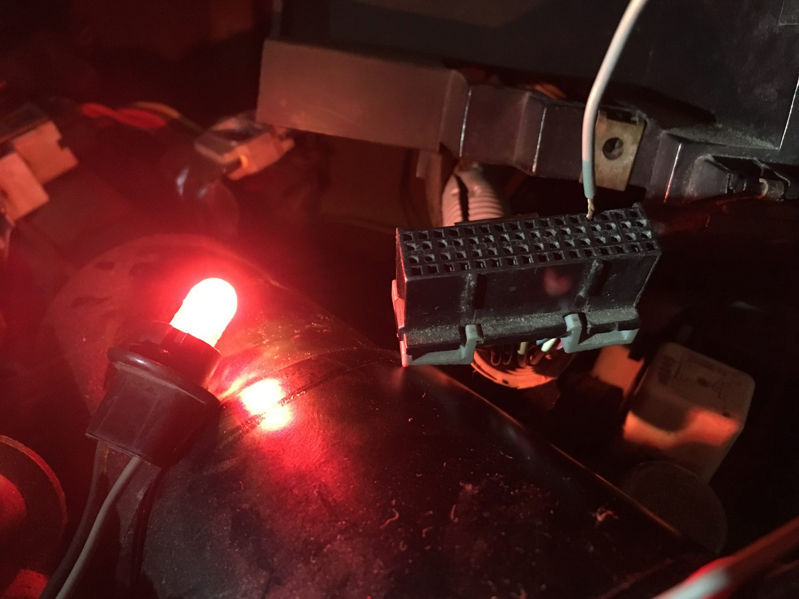
This is the best I can do using a test light,......
First: Remove the Tachometer Filter if there is one installed. (This test will NOT work if the Tach Filter is installed. ) The Tach Filter is normally plugged into the TACH terminal of the distributor cap. Disconnect the Tach Filter at the distributor cap, disconnect it from the Tachometer wire @ the other end, and plug the engine harness Tach wire directly into the distributor cap TACH terminal. Here is a picture of a Tachometer Filter:
Ground the test light.
Probe the cluster plug at terminal 'C13'. It's a WHITE wire.
Turn the ignition key to RUN.
** Light should turn ON
Turn the key to START.
** The test light will "pulse" till the engine is shut off, the probe is removed, or the bub blows.
If this happens,.... the TACH circuit is probably OK.


 Ok so the speedo/odometer is powered by the speed sensor buffer module and only the display value is sent by the vss? Sorry just trying to get that straight.