When you click on links to various merchants on this site and make a purchase, this can result in this site earning a commission. Affiliate programs and affiliations include, but are not limited to, the eBay Partner Network.
Throwing this out to see if anyone has interest...
I`m looking for some consulting / talent to create a model of the third gen spindle, while my 2D talents are excellent, learning 3D while keeping up with the workload has it`s limits. Ambitious is how I would characterize this design intent so if you are current with reverse engineering, working with meshes to develop solids in whatever program you prefer and have time to dedicate to a small project I`d be happy to speak with you and discuss the details. I have a scaled and aligned mesh and have played around creating planes and bringing in solids but I think this would be faster and better for someone who uses these programs daily or often, right now it is in fusion 360 with several iterations of progress although not done by a highly skilled designer (yes me)
I don't often visit the Fabrication forum, or I might've noticed this thread when it was created. Maybe this bump will help.
Manufacture your own, brand new "1LE" spindles, instead of having to modify stock spindles? No more junkyard-hopping to score dirty, rusty old spindles, where pickings are getting slim.
Once a base file is created, then variations would probably be easy. Oh, the possibilities...
Standard style.
1LE-style.
1LE-style "Belltech" drop spindles.
1LE-style drop spindles with short arms that work with wide wheels.
"Corvette" hub-style spindles for 3rdgens, like the ones available for 2ndgens.
Hahaa... I got you out of your comfort zone I see, Yes I think getting it modeled and reversed is step one and I should have came back and updated this earlier but I had a response for what I needed the first day actually so this is in motion already. I noticed you said 1LE 3 times...lol they were merely stock spindles modded just like any brake upgrade commonly done now a days...only magic was the rotor as far as the brakes went, rears were stock equipment...prop valve I cant say was too different if at all either - all the other 1LE specific`s of course really made the car a complete package.
I think a slight drop and sealed hub bearings would really bring these current and open up some wheel choices. Shorter steer arms would quicken the ratio, I wonder what other problems shorter arms would bring with it though, a rack would need to be matched with them I`d think
The repeated 1LE references were for those who live and die by that code. It doesn't mean squat to me, but using the code helps some people visualize the modified spindles.
Hahaa... I got you out of your comfort zone I see, Yes I think getting it modeled and reversed is step one and I should have came back and updated this earlier but I had a response for what I needed the first day actually so this is in motion already. I noticed you said 1LE 3 times...lol they were merely stock spindles modded just like any brake upgrade commonly done now a days...only magic was the rotor as far as the brakes went, rears were stock equipment...prop valve I cant say was too different if at all either - all the other 1LE specific`s of course really made the car a complete package.
I think a slight drop and sealed hub bearings would really bring these current and open up some wheel choices. Shorter steer arms would quicken the ratio, I wonder what other problems shorter arms would bring with it though, a rack would need to be matched with them I`d think
Shorter steering arms would help with bump steer clearances with smaller diameter wheels,IE 16� and 17� wheels. A bump steer kit could be paired with the spindles. The bump steer kit I put together for my car with 17x9.5 wheels I�ve got about 3/16� gap between the rod ends and the wheel, I haven�t measured the bump steer but I feel it�s probably not �correct � if the steering arms were shorter you couple properly set bump steer correction.
Interesting, so if the steer arm was shortened you could drop the link lower matching the lower A-arm angle (is this correct?) how much shorter do you think it would need to be. By the way this exactly the feedback I need thank you
Interesting, so if the steer arm was shortened you could drop the link lower matching the lower A-arm angle (is this correct?) how much shorter do you think it would need to be. By the way this exactly the feedback I need thank you
By shortening the arm that attachment point would be closer towards the center of the wheel therefore gaining more clearance. In my case I�m running the LS1 breaks with 2� spacers and 17x9.5 05 ZO6 wheels that have a -54 back spacing. Again I have measured the bump steer so really have ideal at this point if it�s correct or not, I just extended them as far as possible with enough gap that I felt comfortable with.
Last edited by 91banditt2; Mar 7, 2023 at 07:21 PM.
So dropping the wheel (actually raising the wheel in relation the the steer arm) to make a 1 inch drop spindle would make things worse w/o shortening it is what I am hearing. With the arc the stock steer linkage has to go though at what point will shortening the arms make the tire rods run into arms / end links etc or is that not a possibility
So dropping the wheel (actually raising the wheel in relation the the steer arm) to make a 1 inch drop spindle would make things worse w/o shortening it is what I am hearing. With the arc the stock steer linkage has to go though at what point will shortening the arms make the tire rods run into arms / end links etc or is that not a possibility
Yes, I believe raising the spindle location without relocating the tie rod attachment point would make it worse.
You could look at the 82-04 S10 steering knuckles and their relation with steering arm and spindle, the steering knuckles/spindles are similar to the f-bodies, I�ve read here that some have used the S10 lower control arms on f-bodies.
Yep I get it, the old drop bell techs for the third gen were really picky on wheels they would work with. The lower S-10 and G body a arms are the same as the F body, the bushings differed though- no different than the old Lee Iacocca who lead ford and eventually Chrysler`s one car 10 models program - smoke and mirrors but to his credit he did save the whole company with that move. I love that GM uses shelf parts that interchange across multiple platforms and year spans That G body/S10 spindle is an exact replacement to a third gen save for the upper mount and two dust shield bolt hole locations. same shitty brakes haha
I can probably model the spindle pretty good, I've been using Solidworks to make 3d printed stuff for a year. I've actually thought about doing it on my own (see my other threads about bending factory spindles) but that doesn't mean I would have a way of getting something useful out of all that work.
I can probably model the spindle pretty good, I've been using Solidworks to make 3d printed stuff for a year. I've actually thought about doing it on my own (see my other threads about bending factory spindles) but that doesn't mean I would have a way of getting something useful out of all that work.
that would be great if possible, i wonder though if the 3rd gen F body geometry of the strut attachment though is going to reasonably allow an integrated bearing hub to be accommodated. certainly significant changes to the spindle geometry would be needed that would require a good mechanical analysis
that would be great if possible, i wonder though if the 3rd gen F body geometry of the strut attachment though is going to reasonably allow an integrated bearing hub to be accommodated. certainly significant changes to the spindle geometry would be needed that would require a good mechanical analysis
Ultimately it would be great to start with a clean slate but we are given the mount points as they were delivered back in 1982 and to make new tech fit old tech sometimes compromises have to be made. What compromises can you make? not safety for sure ! ... so what do you give up to not compromise that? track width? weight? During the process of reversing it to geometry only, it was clear the reason many have not attempted a updated part (it is very compact to start with). I feel like we have a good design going and comparing to several "updated" spindles for similar type applications, we will be exceeding those efforts for strength at the minimum- for the most part overbuilding...I would love to post a pic of what we have but that will need to wait a bit longer. We are close though so stay subscribed
Ultimately it would be great to start with a clean slate but we are given the mount points as they were delivered back in 1982 and to make new tech fit old tech sometimes compromises have to be made. What compromises can you make? not safety for sure ! ... so what do you give up to not compromise that? track width? weight? During the process of reversing it to geometry only, it was clear the reason many have not attempted an updated part (it is very compact to start with). I feel like we have a good design going and comparing to several "updated" spindles for similar type applications, we will be exceeding those efforts for strength at the minimum- for the most part overbuilding...I would love to post a pic of what we have but that will need to wait a bit longer. We are close though so stay subscribed
In R&D working on electrical transmission/switchgear there are some scenarios where there are to many variables and due to safety concerns it�s best to over engineer certain parts ie, bigger heavier parts, larger bolts, ect. Smaller parts manufacturers don�t have the budget for rigorous testing of parts to failure so it�s best to air on the side of caution and make the parts more beefy.
Going over a few ideas prompted me to post, how important do you feel keeping the stock track with the brakeupgrade installed is ? As it stands now when we upgrade a factory spindle the track grows by the thickness of the new rotor hat so approx .300-.335 depending on the rotor. So most anyone who has upgraded their 3rd gen brakes has accepted or accounted for in someway to allow for this. At a fork in the road on which way to go...on one hand we have probably 50% or more of 3rd gens out there with modded brake systems already who have dealt with the track increase from that brake swap, on the other hand keeping stock track width WITH the new brakes does sound desirable too but will possibly play havoc on a set up that is already existing...whats your thoughts?
I have no first hand experience, but my plan is "LS" brakes all around, and 4 front factory 16" PW7s, and no body mods. From what I have read this is a combo that can be accomplished on a Firebird. I already have the wheels, tires and brakes, so I certainly hope it is. I wasn't planning (desiring) to use spacers, unless essential to the success of the project, then I'll do what I must.
Going over a few ideas prompted me to post, how important do you feel keeping the stock track with the brakeupgrade installed is ? As it stands now when we upgrade a factory spindle the track grows by the thickness of the new rotor hat so approx .300-.335 depending on the rotor. So most anyone who has upgraded their 3rd gen brakes has accepted or accounted for in someway to allow for this. At a fork in the road on which way to go...on one hand we have probably 50% or more of 3rd gens out there with modded brake systems already who have dealt with the track increase from that brake swap, on the other hand keeping stock track width WITH the new brakes does sound desirable too but will possibly play havoc on a set up that is already existing...whats your thoughts?
I think the extended track is not an issue, as noted it is really now more the "standard" track anyways for anyone who is interested in upgrades at this point. i wouldn't extend beyond this however
I dont think id want to go any wider either. On top of the rotor, i have BBU's aluminum hubs and i think they are .5 taller than non 1LE style hubs (correct me if im wrong on that). Plus the 1/4 spacer for the hawks GTA wheels.
The billet hubs keep the exact width of the stock 10.5" brake track width, when you add the rotor over them thats when you extend track past stock. Most stock rotors are .300-.335 thick so you are + 5/16" or there about right now (per side)
So with the new knuckle, it wont extend track any further than a stock spindle with a brake upgrade- so no wider than what is now in use. I was just questioning should we attempt to keep it all in the stock track, new brakes and all. so Minus 5/16 from a brake upgraded cars track width
I have over 16 years of experience with SolidWorks as a mechanical engineer. I have been a product design engineer that entire time as well. 6 of which was spent reverse engineering things to be machined, cast, stamped and molded.
Is the current mission to simply get the Fusion 360 into a parametric SW file?
The billet hubs keep the exact width of the stock 10.5" brake track width, when you add the rotor over them thats when you extend track past stock. Most stock rotors are .300-.335 thick so you are + 5/16" or there about right now (per side)
So with the new knuckle, it wont extend track any further than a stock spindle with a brake upgrade- so no wider than what is now in use. I was just questioning should we attempt to keep it all in the stock track, new brakes and all. so Minus 5/16 from a brake upgraded cars track width
I think those that would go through the trouble of swapping out the spindles are probably ok with adding a spacer on the rear if the difference in track width bugs them. Are there any negatives in reducing the spindle shaft by 5/16"? Though the LS1 front brake retrofit is a very common affordable brake upgrade I say there are way more factory front brake cars than LS1 front brake cars. If these are made to the factory spindle shaft length, I would think you would have a wider customer base than if you make them shorter. Either way the end user would probably be using a wheel spacer one way or another if the retain the factory wheels.
Is this project still moving forward? I have not been contacted.
If the scaled mesh file imports into SolidWorks, it might not be a very hard job to get this model into something more usable.
The machined shaft parts will need much higher detail. Only acquired with calipers and a good OEM unit. Maybe that info is somewhere online already.
I am interested because my restomod build currently has no spindles and I have plans on buying Bear brakes and billet three piece wheels for the car.
Bear says they have spindles they provide with their brake setups, but I want to entertain other options like C7 brakes on stock spindles.
But since I don't have any spindles I need to get my hands on some. Since this is high end (at least to me) build, I really don't want to get junkyard parts and put them on this build.
Making something new sounds interesting.
It is very much moving forward !, actually it is about completed (design), there will be no "pin" these are going to use C7 hub bearings. Shortly after creating this post another member who is very qualified stepped up and wanted to be part of the project and to say the least he is very thorough and explores every possible aspect of the design. I was hoping to debut a rendering here and it is close to completed. I will post that as soon as it is presentable of course.
This build to start with is designed as a bar stock build, so plate steel formed bolted / welded, will accommodate any brake set up with interchangeable brackets. Weight is similar to stock and we have been pushing forward with the stock height version so far, there is a 1.5 drop version that is already concept but needs some finishing to the drawing. Once these are done, I will be looking for candidates to test, ideally autocross cars with optimized handling that can exert more than average forces to these. Stay subscribed I'll try to update this later this week.
Selecting wheel offsets, backspacing and calculating fitment will be so much easier.
No more tall factory hub that dictates the thickness of spacers or adapters.
1.5" drop will be nice. Not too much and not too little. Will probably work with a wide wheel. And people can still use lowering springs or weight jacks, if they want or need to dial it down further.
Most of you don't know this, but when Scott is out in his shop working, he wears shirts with a big red S on them.
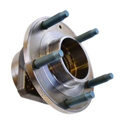
Previews ! This set of images are the results of a lot time and hard work of the designer, a member here, he has taken this project and made it what it is today, one step closer to reality. I wanted to get the stock spindle geometry first, do the updates I feel it needs then after we test and build and test some more make these available. Right now although it appears to be completed we are just at the threshold, we have a good model to FEA and pending that we maybe able to cut some parts. Right now it is the stock spindle, I had a choice to make to start the design and that was how it would be built, to start I choose bar stock because it will give us a good foundation with probably the lowest initial investment and a very strong part, billet or cast could be in the future one day but right now, I`m just a little fish in a big bowl. So one step at a time and once this is a go then I can think about doing a similar one with the drop which actually looks like it might be easier to pull off. Modifications for Ackerman and steer arm length did not fall on deaf ears but that is something we can look at once this is truly viable. Questions? just let me know- Couple of key points
Uses C5/C6/C7 or Gen5 Gen6 hub bearings
Stock height, stock ball joint and tie rod locations
Weight is equal to or slightly less than a stock spindle and hub
Adaptable to most any brake system with bolt on prefabbed brackets
Damn, that Looks great.
Is that the same hub as used on the 98-up S10 blazers?
Is that what the knuckle will use or the current hubs that you sell?
No sir, that would the Corvette hub. Ideally the best one to use would be the C7 so 2014-19 corvette fronts. You could also use several others that have the same bolt patern, 1997-2004 C5's and also the 2005-13 the C6`s.
All of these have the same bolt pattern (5 x 4.74) and register for the rotor 2.779. All of these hubs also have the same lug stud as the 3rd gen, M12 x 1.5. The C5-C6 have a pigtail for the ABS signal.
The C7 is the favored hub because it has the largest bearings without the pigtail. The C6 ZR1 hub also has the same size bearings and additionally the abs pigtail.
Previews ! This set of images are the results of a lot time and hard work of the designer, a member here, he has taken this project and made it what it is today, one step closer to reality. I wanted to get the stock spindle geometry first, do the updates I feel it needs then after we test and build and test some more make these available. Right now although it appears to be completed we are just at the threshold, we have a good model to FEA and pending that we maybe able to cut some parts. Right now it is the stock spindle, I had a choice to make to start the design and that was how it would be built, to start I choose bar stock because it will give us a good foundation with probably the lowest initial investment and a very strong part, billet or cast could be in the future one day but right now, I`m just a little fish in a big bowl. So one step at a time and once this is a go then I can think about doing a similar one with the drop which actually looks like it might be easier to pull off. Modifications for Ackerman and steer arm length did not fall on deaf ears but that is something we can look at once this is truly viable. Questions? just let me know- Couple of key points
Uses C5/C6/C7 or Gen5 Gen6 hub bearings
Stock height, stock ball joint and tie rod locations
Weight is equal to or slightly less than a stock spindle and hub
Adaptable to most any brake system with bolt on prefabbed brackets
Looks fantastic!
Question about manufacturing? Working in R&D that's part of my professional world. This is more than likely a small volume part were only a small portion of the third gen enthusiast is going to be able to justify the cost for their project. What steps are you planning on taking to ensure repeatability of assembly/quality? Looks like a lot of welding involved so with a lot of heat comes issues, assuming you would weld components in stages not to transmit heat throughout the part? Any discussions on developing a weld fixtures for repeatability?
So during design that was one of the key points we kept in mind (ease of assembly) so these of course will be laser cut so that is very repeatable, the bearing holes will align all the main parts together, the strut mounts are keyed so they will locate by themselves. The lower ball joint`s angle is set by the gussets, also keyed. That ball joint block and gusset set we have to locate probably with a laser cut slot in the back plate, the steer arm tie rod mount is something we were discussing yesterday on how to locate that. A simple fixture will be all that is needed we think. You guys are in the front row, virtually on the cusp of the development of this so some things are still unknowns but we have to start somewhere and will tackle problems as the make themselves known. This is something that is long overdue for this car and I`m here doing this looking for your feedback and your questions so dont hold back
Mechanical Engineer here: Chances are this has been done, but would be great to see here in the thread is an image of the scanned OEM spindle with an overlay of the current design.
See how all the mating features and angle/sweep of shapes match up from the fabricated unit to the stock one.
Any plan for steering lock out stops?
Good question, would the factory steering stops on the lower control arms be able to be used or would these need to be modified?
Random thoughts that I�m sure are lower on the priority list.
Would these be delivered zink plated, powder coat or bare?
Looks like a stacked plate design, would components be fully welded, if not bare parts will rust in between the parts, even if zink plated parts will rust in between. If powder coated that would completely encapsulate the parts but the ball joint taper would need reamed out.
Steer stops if we do it will be part of the brake bracket, if you notice that stop is well offset to the rear and outboard of this fabricated deign. It will be a stacked plate design and zinc plating is what I was thinking, you can powder coat over zinc if you want but honestly I`m not going to try and deal with a powder coater not overlaying the product and causing fitment issues before they are even on the car. Having dealt with literally thousands of spindles I can say it all depends on the conditions your in as to what will happen corrosive wise to steel parts out in the elements. Most track cars do see more garage or enclosed trailer than the elements
This design will allow us to clock calipers much higher than the stock spindle so clearance problems you would have on the stock one most likely will not apply to this one
It is very much moving forward !, actually it is about completed (design), there will be no "pin" these are going to use C7 hub bearings. Shortly after creating this post another member who is very qualified stepped up and wanted to be part of the project and to say the least he is very thorough and explores every possible aspect of the design. I was hoping to debut a rendering here and it is close to completed. I will post that as soon as it is presentable of course.
This build to start with is designed as a bar stock build, so plate steel formed bolted / welded, will accommodate any brake set up with interchangeable brackets. Weight is similar to stock and we have been pushing forward with the stock height version so far, there is a 1.5 drop version that is already concept but needs some finishing to the drawing. Once these are done, I will be looking for candidates to test, ideally autocross cars with optimized handling that can exert more than average forces to these. Stay subscribed I'll try to update this later this week.
You have me interested.
And if we need some crowd funding to kickstart things, even if I wasn't going to buy a set, I would be interested in helping to fund the work.
Scott, I have a set of your modified spindles on my GTA now with LS1 conversion brakes, and they've been awesome this whole time, so much better than stock brakes.
i think this is a great development and would be interested in several sets of these if they are safe and reliable.
the downfall with fabricated spindles ends up being can a welded spindle withstand street duty as the consequence of failure is so high, and even if the design can and prototypes can, can manufacturing be controlled to be repeatable.
there are large advantages with the manufacturing of OEM spindles that go way beyond cost that includes the ductility and capability of the forged spindle
Thank you, comments like yours are exactly why I wanted to put this out here, some comments spurs questions that do not have the easiest answers- but it`s those questions that make us look and not say "...it`s good enough" but.."how can we make it better?" in the beginning of the process you have to choose, how will these be made....sure, I could go off into fantasy land and develop something that would be the ultimate but could I produce it? so you have a fork in the road and you have to choose realistically based on the time, capitol and realistic understanding on what they can be produced and sold for (remember they are for a 3rd gen). So sure- lets 5 axis them out of 7075 so that they are 4k a set right? nope its not going to be profitable ever, it would be really cool, really light and strong etc but how many guys are going to get in line for that...Cast, sure that is going to be the least amount of cost per part and have good strength ... once you can afford the volume, not too mention the molds and then trying to control offshore production of a small run. I need to keep it in my wheel house so bar stock is something we can control right here right now and will fit the needs
During the time spent looking at a few different approaches the main goal was too eliminate weaknesses and overbuild it so that if it were put on the street that it would survive just fine. Taking the pin out of the equation simplified it greatly in my opinion, this probably would have been the point of most flex and concern but that being out of the picture the strut or ball joint mount becomes the next obvious thing to look at. Now while a single piece of 5/8 HR and some tubing can replicate that mount, is it the strongest we can make it? probably not. I looked extensively at failed fabricated spindles and most times it was the weld itself that would lead to a problem. The quality of the weld or just the shear forces put on that point. Right now like I mentioned, you guys are front row, these have not been simulated FEA tested yet but it is coming and that should show us any problem areas.
The manufacturing company I use for my laser cutting,bending,welding do trainloads of fabricated parts, all identical so that capability is there, of course when you are doing several hundred or thousand parts that repeatability comes in just fine, now when you make them 2 sets at a time 5 sets at a time I can see that possibly causing some variances. This manufacturer however is ideal for this build, they deal in a lot of thick weldments - light poles, guard rails, building facades, They manufacture truck beds (large stake type) Truck boxes etc...then they build a lot of police car equipment, which is exacting tolerance, each piece must be the exact same. Building police cars myself for 15 years, installing containment systems, trunk trays, gun mounts, light mounts, push bumpers I can tell you there is no room for error with the parts that are fitted to these cars and SUV`s. So my confidence that they can in fact replicate them within reason is high.
Having a one piece cast nodular iron / steel spindle or knuckle is in fact the goal, I dont know if I'll ever be big enough to do it but everything has to start somewhere. The last spindles GM forged were back in the early 70`s, so the stock ones are not forged, cast steel probably 1040 or 1045 alloy The stock ones are ductile, I have straightened many bent steer arms on the press over the years.
These wont be for everyone but for the folks that do need it, it will be perfect because -simply- there isn't anything available like it nor will there be it appears, this platform is what 41 years oldest, 31 years youngest now? I think if it were going to be done it would have been a while ago now right?