
LT1 harness: Start to Finish

Thread Starter

Joined: Jun 2005
Posts: 8,122
Likes: 362
From: NC
Car: 91 Trans Am
LT1 harness: Start to Finish
Ok, this thread will be a basic overview of how to build a LT1 swap harness and merge it to a 3rd gen harness. Please read this thread about preparing the 3rd gen harness
https://www.thirdgen.org/forums/ltx-...p-3rd-gen.html
Next, gather the 3rd gen body pinouts per year along with as many diagrams for the LT1 as you can find. Bear in mind 92-93 LT1s are completely different animals than the 94+. 94-95 are considered the "golden" years for their ease to retune and being so common. 96-97 are slightly different, but nothing to worry about if changing from OBDI to OBDII or reverse
https://www.thirdgen.org/forums/ltx-...p-3rd-gen.html
http://www.lt1swap.com/all_lt1.htm
Here is an overview of all the tool used to build a harness. These will set you back about $80 total and can be found at any radioshack
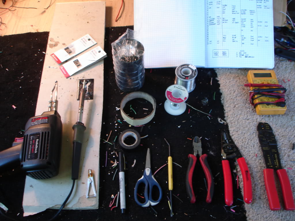
Start off with the guns. 98% of the job will be done with the 30A pencil iron. Any 18-20ga wires this thing will do instantly. Any of the heavier wires like the main battery or ground cables are 10-12ga so the 120A gun is needed. You can build the whole thing with the large gun, but it takes a few seconds to heat up with each joint so the job will take even longer. Below is a small scissors clamp to hold cables together while solder is flowed in
Above is two stacks of common resistors. Each pack of 5 should set you back a whole dollar. 470ohm resistors are used for LT1 harnesses in place of the dummy light for the alternator. Firebird LS1 swaps use the 680ohm stack to boost the tach signal to their factory gauge
Notice there are a pair of strippers and crimpers. Only use the crimpers for attaching ring terminals. DO NOT use the stripper section. After a few attempts you'll see why
I suggest a harbor freight value pack of electrical tape. Each harness will use 4-5 rolls. White masking tape is used for labels and to wrap up connector pigtails
For your solder find a diameter that you're comfortable with, but be sure it's rosein core. I use .062" in 1lb rolls. 1lb will build about 12 harnesses, so dont think you NEED this much
Last are two pieces generally overlooked, notebook full of condensed pinouts, diagrams and basic routing and a multimeter. This is a $15 advance auto special, but a $3 HF unit will work just as good. For the job we're only using the resistance part. Be sure whatever you use can measure in 1/10 of an ohm
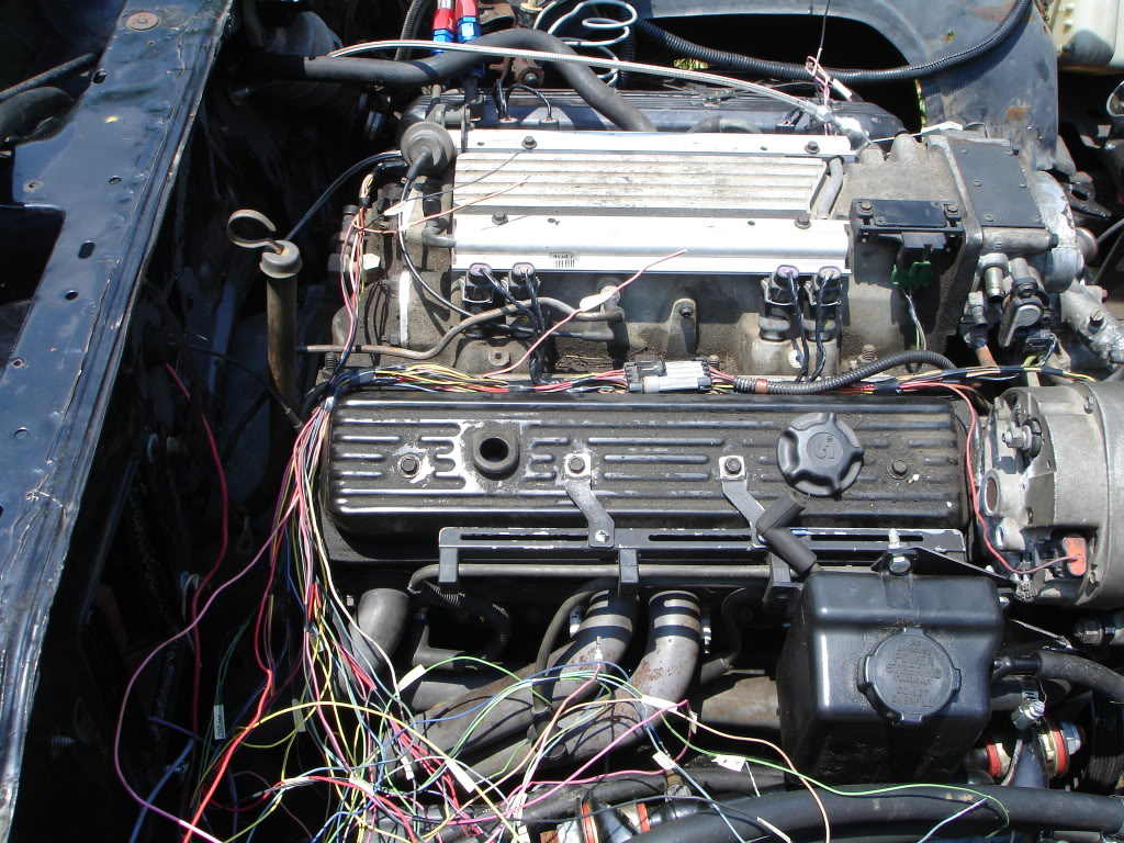
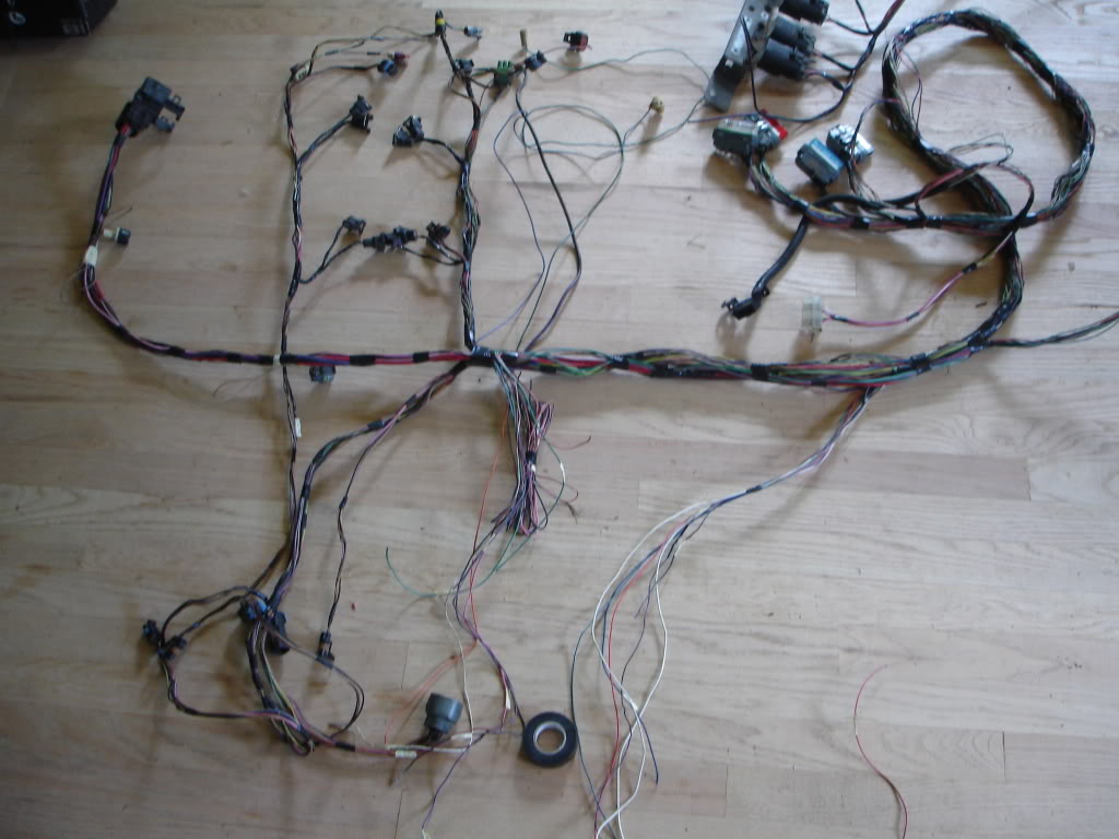
Now onto the actual harness. Here is a 91 3rd gen harness to be mated to a 96 Fbody LT1 T56 and converted to 4L60E
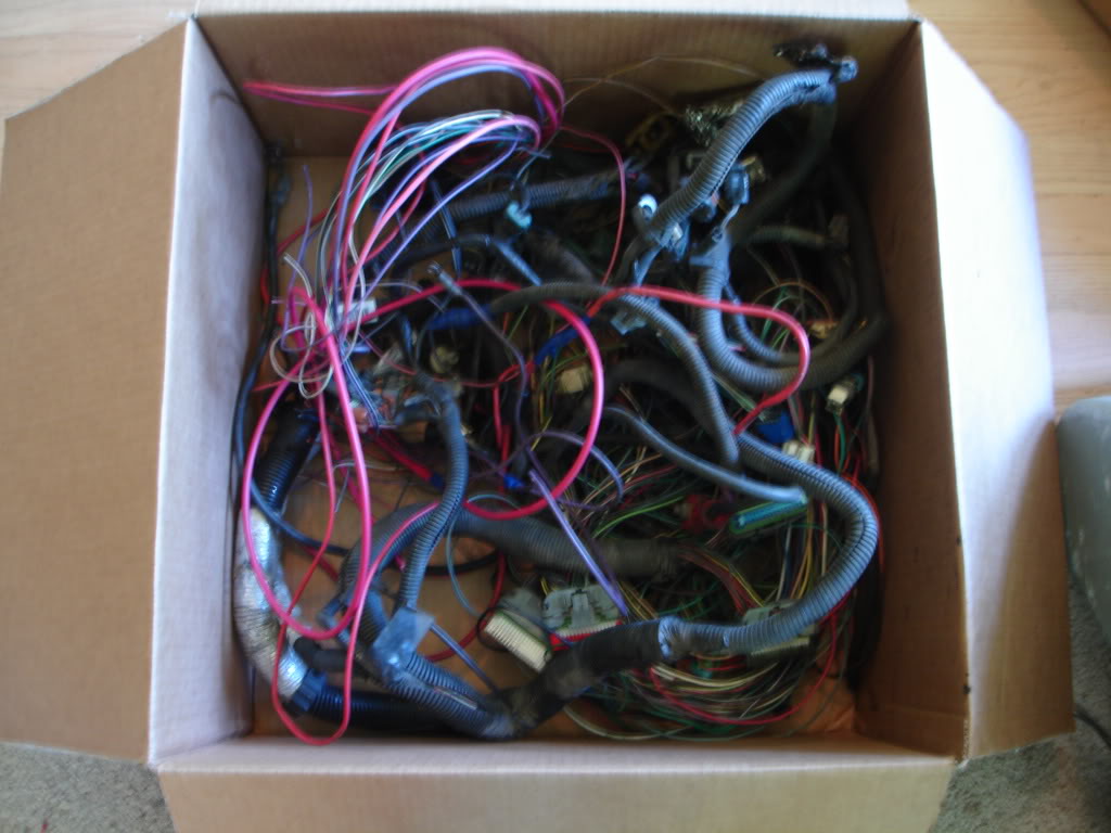
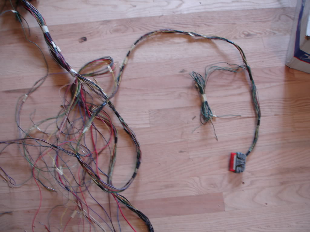
Locate the PCM connectors and body connectors

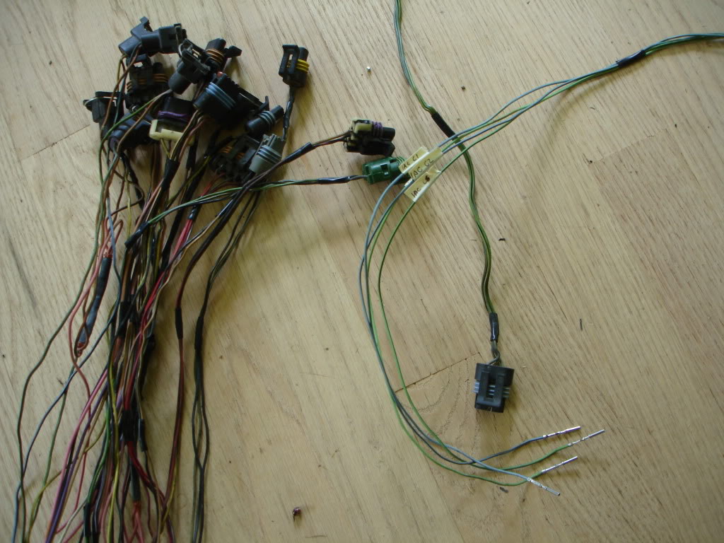
Depined. Use a pick or small screwdriver to depin the PCM connetors. A small paperclip is needed for the body connectors
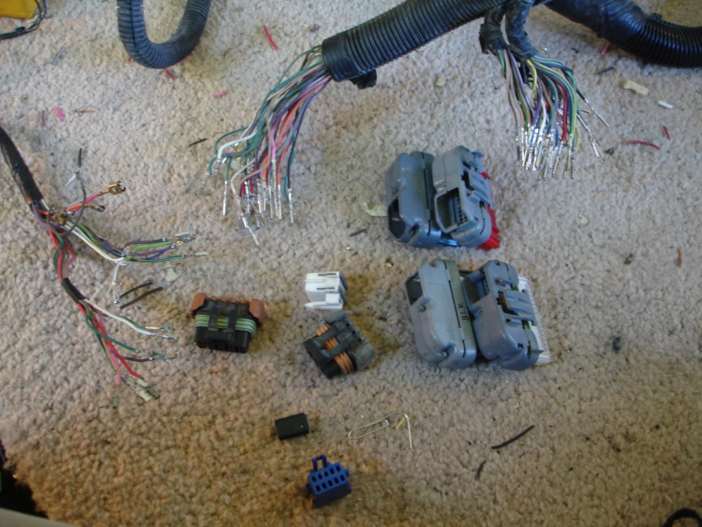
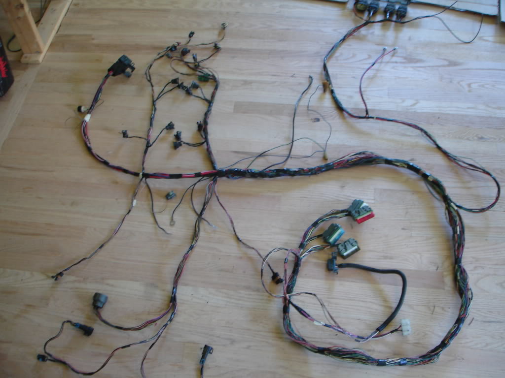
Deloom, untape and label everything
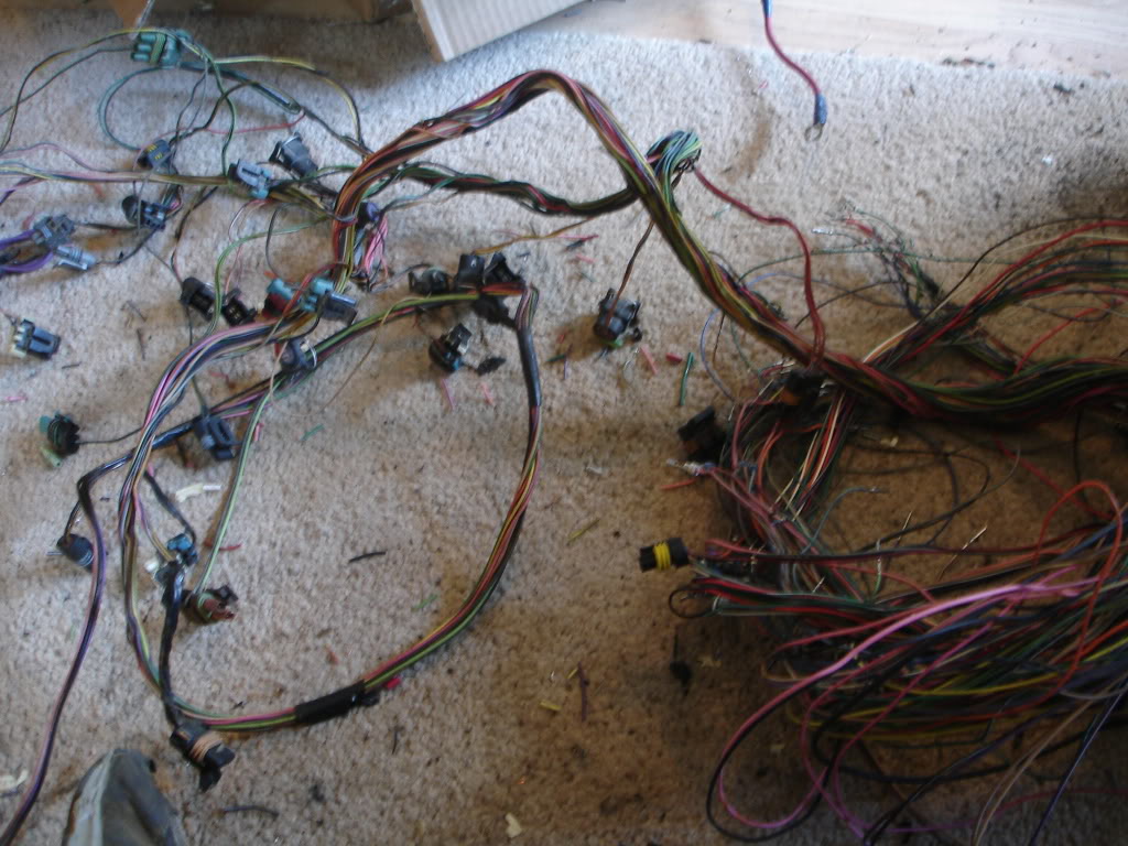
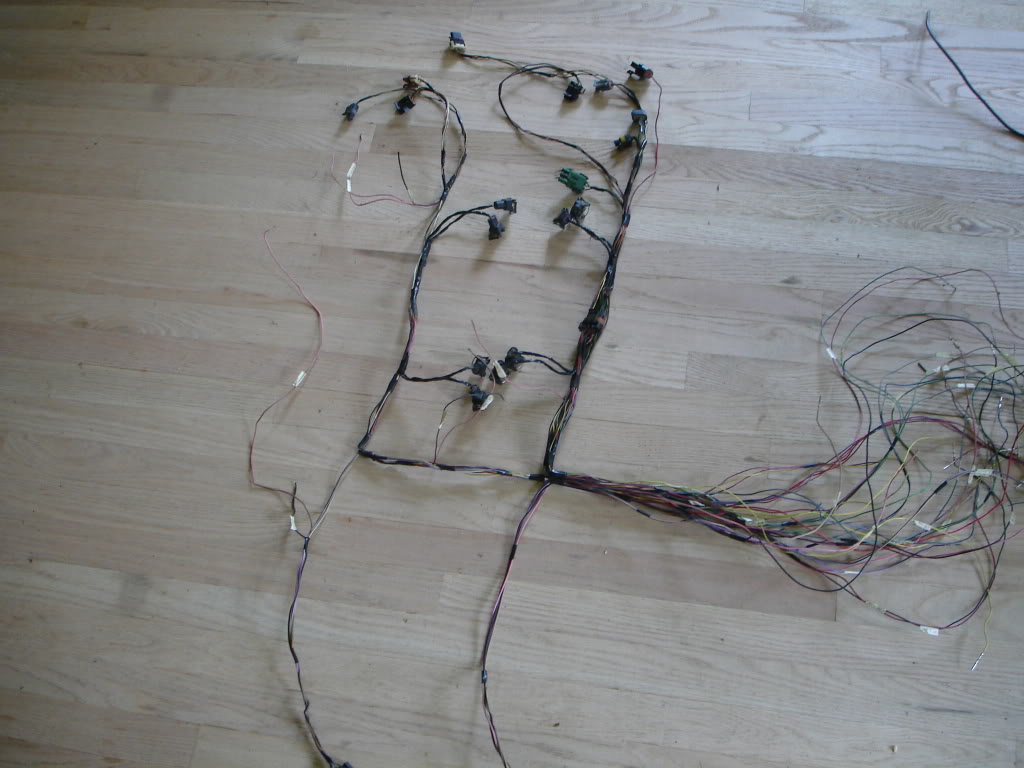
Disassemble it like you did the 3rd gen half, cutting commons and wrapping up the lengths of wire. Odd point of fact, the Fbody LT1s use one INJ fuse, while pretty much every other engine uses two. Luckily a long runner wire is used to join the banks. Cut it free and its officially got two INJ bank fuses
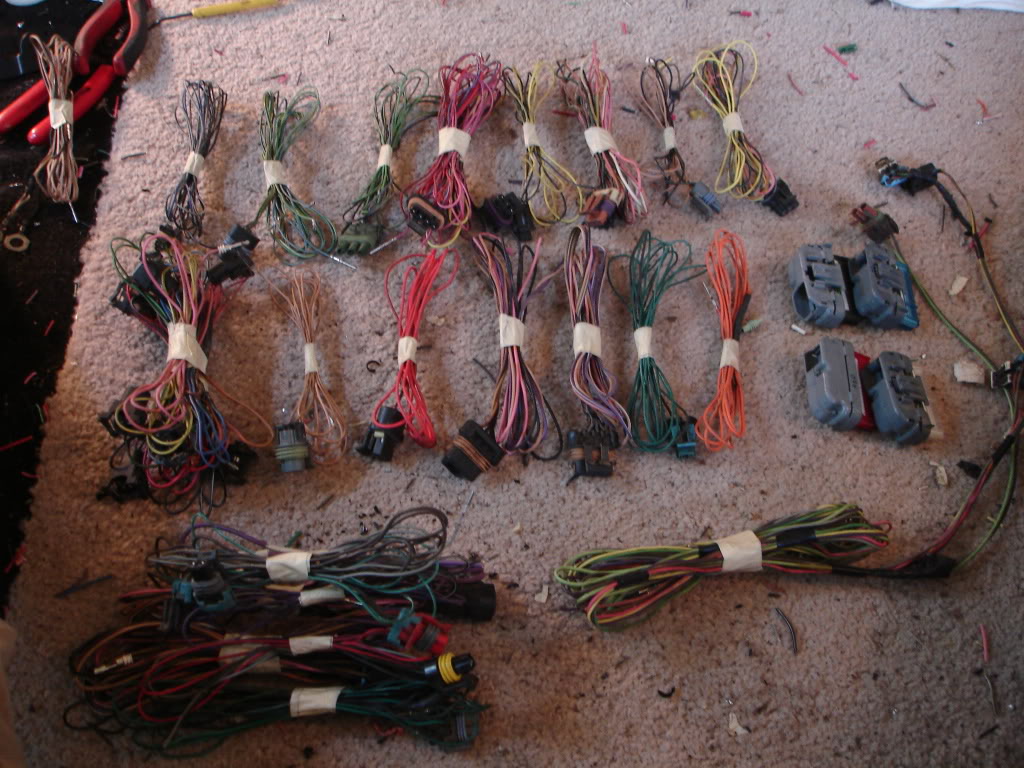
Once everything is disassembled, unravel each and bind the group with electrical tape every foot or so. This cuts down on tangles and makes routing easier. Also, if a label falls off you can identify it by association instead of having to ohm out the entire harness. Label the wires at the PCM end too
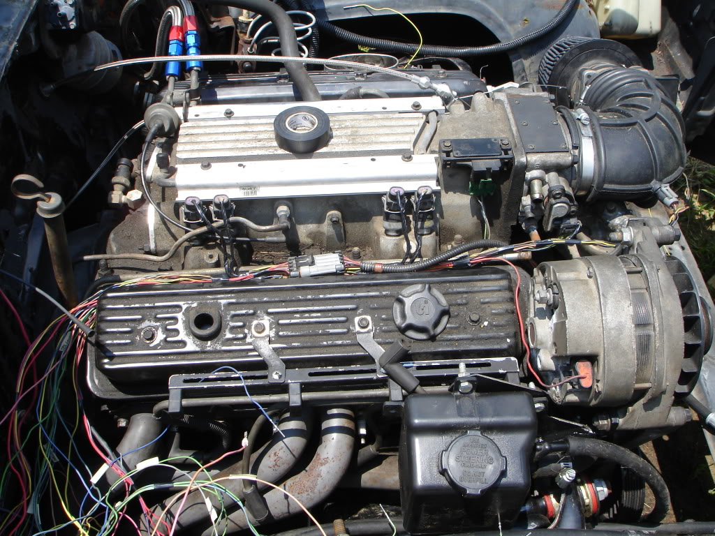
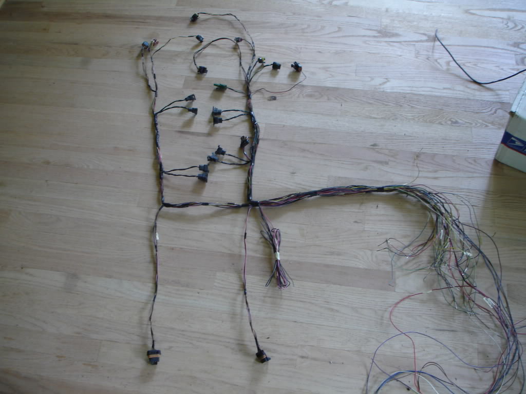
Now get a mock-up engine. It doesnt have to be in a car, we're only setting the sensor lengths. Plug everything up and drape the wires roughly to where they will be going
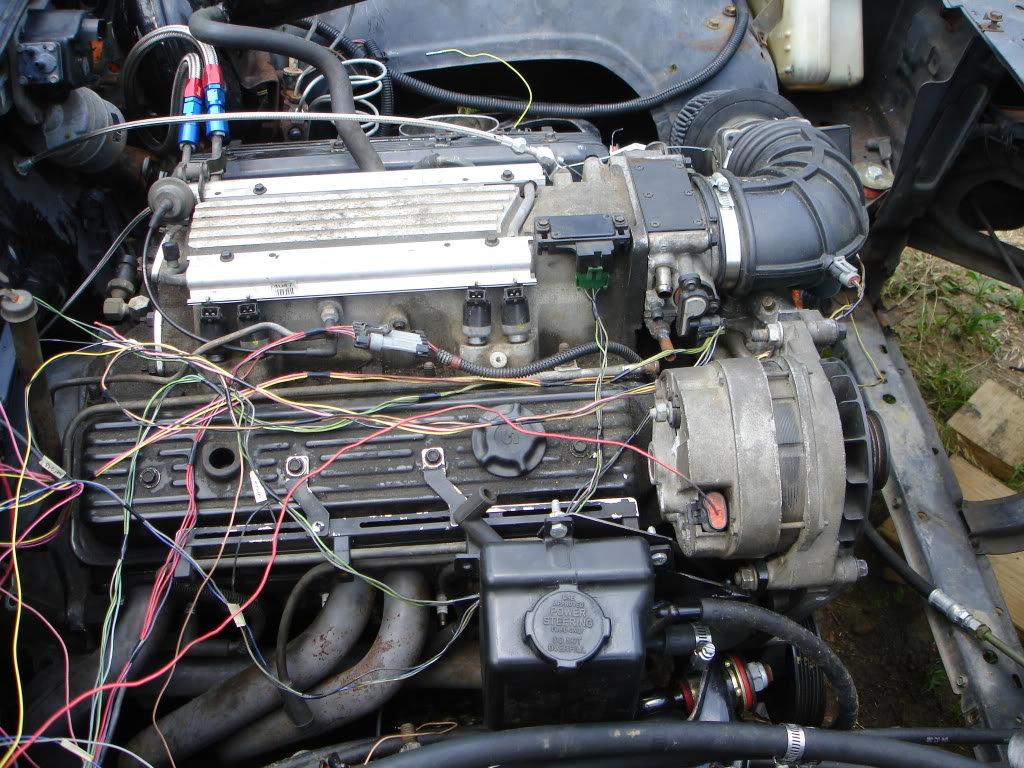
Bound with tape. Be sure no wires are pulled taught
https://www.thirdgen.org/forums/ltx-...p-3rd-gen.html
Next, gather the 3rd gen body pinouts per year along with as many diagrams for the LT1 as you can find. Bear in mind 92-93 LT1s are completely different animals than the 94+. 94-95 are considered the "golden" years for their ease to retune and being so common. 96-97 are slightly different, but nothing to worry about if changing from OBDI to OBDII or reverse
https://www.thirdgen.org/forums/ltx-...p-3rd-gen.html
http://www.lt1swap.com/all_lt1.htm
Here is an overview of all the tool used to build a harness. These will set you back about $80 total and can be found at any radioshack
Start off with the guns. 98% of the job will be done with the 30A pencil iron. Any 18-20ga wires this thing will do instantly. Any of the heavier wires like the main battery or ground cables are 10-12ga so the 120A gun is needed. You can build the whole thing with the large gun, but it takes a few seconds to heat up with each joint so the job will take even longer. Below is a small scissors clamp to hold cables together while solder is flowed in
Above is two stacks of common resistors. Each pack of 5 should set you back a whole dollar. 470ohm resistors are used for LT1 harnesses in place of the dummy light for the alternator. Firebird LS1 swaps use the 680ohm stack to boost the tach signal to their factory gauge
Notice there are a pair of strippers and crimpers. Only use the crimpers for attaching ring terminals. DO NOT use the stripper section. After a few attempts you'll see why
I suggest a harbor freight value pack of electrical tape. Each harness will use 4-5 rolls. White masking tape is used for labels and to wrap up connector pigtails
For your solder find a diameter that you're comfortable with, but be sure it's rosein core. I use .062" in 1lb rolls. 1lb will build about 12 harnesses, so dont think you NEED this much
Last are two pieces generally overlooked, notebook full of condensed pinouts, diagrams and basic routing and a multimeter. This is a $15 advance auto special, but a $3 HF unit will work just as good. For the job we're only using the resistance part. Be sure whatever you use can measure in 1/10 of an ohm
Now onto the actual harness. Here is a 91 3rd gen harness to be mated to a 96 Fbody LT1 T56 and converted to 4L60E
Locate the PCM connectors and body connectors
Depined. Use a pick or small screwdriver to depin the PCM connetors. A small paperclip is needed for the body connectors
Deloom, untape and label everything
Disassemble it like you did the 3rd gen half, cutting commons and wrapping up the lengths of wire. Odd point of fact, the Fbody LT1s use one INJ fuse, while pretty much every other engine uses two. Luckily a long runner wire is used to join the banks. Cut it free and its officially got two INJ bank fuses
Once everything is disassembled, unravel each and bind the group with electrical tape every foot or so. This cuts down on tangles and makes routing easier. Also, if a label falls off you can identify it by association instead of having to ohm out the entire harness. Label the wires at the PCM end too
Now get a mock-up engine. It doesnt have to be in a car, we're only setting the sensor lengths. Plug everything up and drape the wires roughly to where they will be going
Bound with tape. Be sure no wires are pulled taught
Thread Starter
Joined: Jun 2005
Posts: 8,122
Likes: 362
From: NC
Car: 91 Trans Am
Re: LT1 harness: Start to Finish
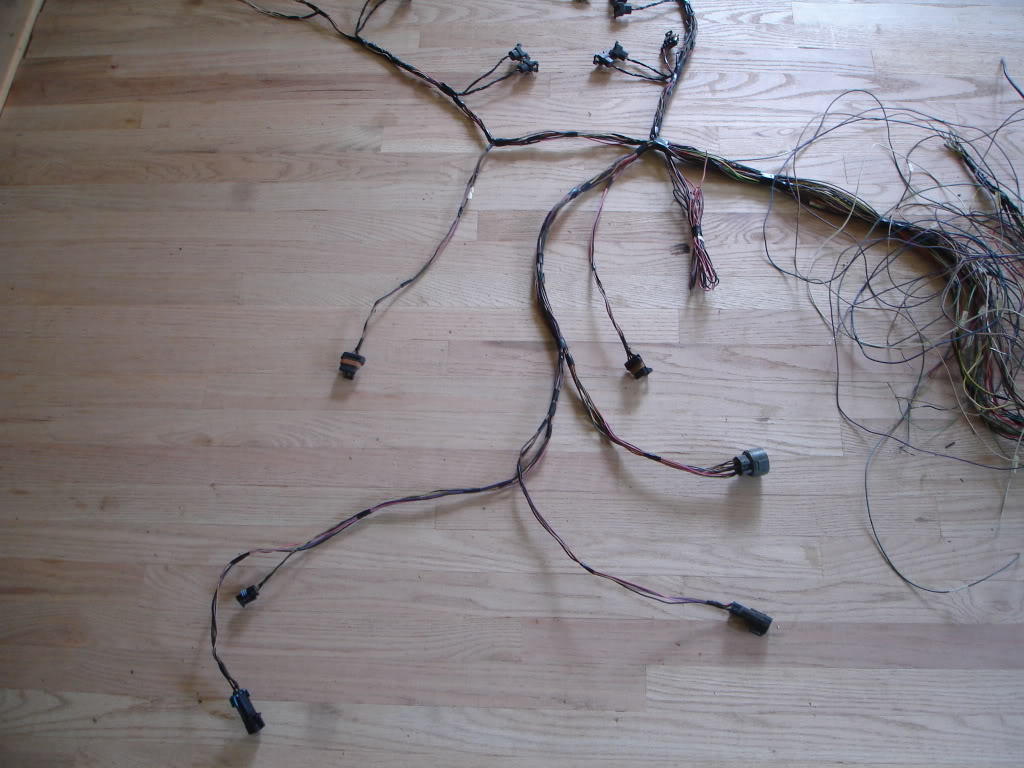
Drivers side bound
Removed and set out. Pull the various IGN/ground wires from the bundles and route the PCM rats nest over to the side. The next job is to reconnect the IGN/grounds back together
Excess length is wrapped up to be connected at the end
Trans wiriring is added. This particular harness uses rear O2s, so those are also added. This is why it makes no difference what the trans type of the original harness is when starting. Switching T56 to auto or removing the wiring completely is done directly. 4L60E connectors are found on ANY 90's RWD trans GM built. T56 reverse lockout and reverse lights connectors can be salvaged from the 3rd gen smog and EGR connectors respectively
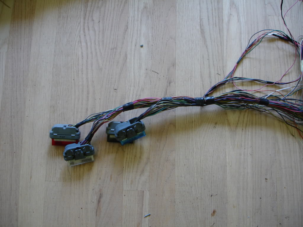
Now, set the PCM location and begin lengthening wires. For the cleanest PCM connectors, run each individually. THis is where the bulk of your time will be spent on the job. Red connector done
All 4 done. Notice the C207/ALDL wires are pulled free, but still loose. OBDI swaps can reuse the 3rd gen ALDL by connecting two wires into the C207. OBDII swaps require a newer ALDL salvaged from any 96+ GM vehicle. THe old ALDL can be cut out or simply ignored
Next, we begin to mate the 3rd gen to LT1 harness. Old pic from a LS1 showing the basics
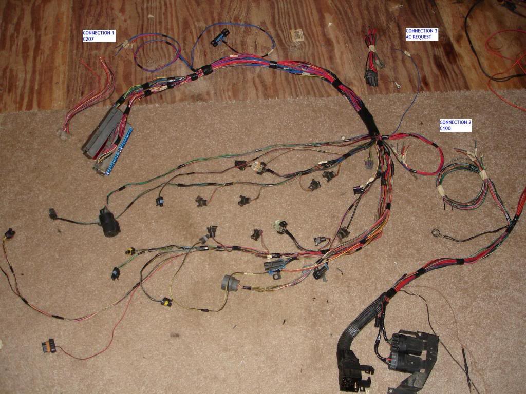
LT1 on top, 3rd gen on bottom. This 3rd gen has remote relays so it looks a little different
3rd gen bound to the LT1. 3rd gen splices on the left, LT1 on th right. If you have more wires on one side than the other, you missed something!
Removed and set out. Pull the various IGN/ground wires from the bundles and route the PCM rats nest over to the side. The next job is to reconnect the IGN/grounds back together
Excess length is wrapped up to be connected at the end
Trans wiriring is added. This particular harness uses rear O2s, so those are also added. This is why it makes no difference what the trans type of the original harness is when starting. Switching T56 to auto or removing the wiring completely is done directly. 4L60E connectors are found on ANY 90's RWD trans GM built. T56 reverse lockout and reverse lights connectors can be salvaged from the 3rd gen smog and EGR connectors respectively
Now, set the PCM location and begin lengthening wires. For the cleanest PCM connectors, run each individually. THis is where the bulk of your time will be spent on the job. Red connector done
All 4 done. Notice the C207/ALDL wires are pulled free, but still loose. OBDI swaps can reuse the 3rd gen ALDL by connecting two wires into the C207. OBDII swaps require a newer ALDL salvaged from any 96+ GM vehicle. THe old ALDL can be cut out or simply ignored
Next, we begin to mate the 3rd gen to LT1 harness. Old pic from a LS1 showing the basics
LT1 on top, 3rd gen on bottom. This 3rd gen has remote relays so it looks a little different
3rd gen bound to the LT1. 3rd gen splices on the left, LT1 on th right. If you have more wires on one side than the other, you missed something!
Thread Starter
Joined: Jun 2005
Posts: 8,122
Likes: 362
From: NC
Car: 91 Trans Am
Re: LT1 harness: Start to Finish
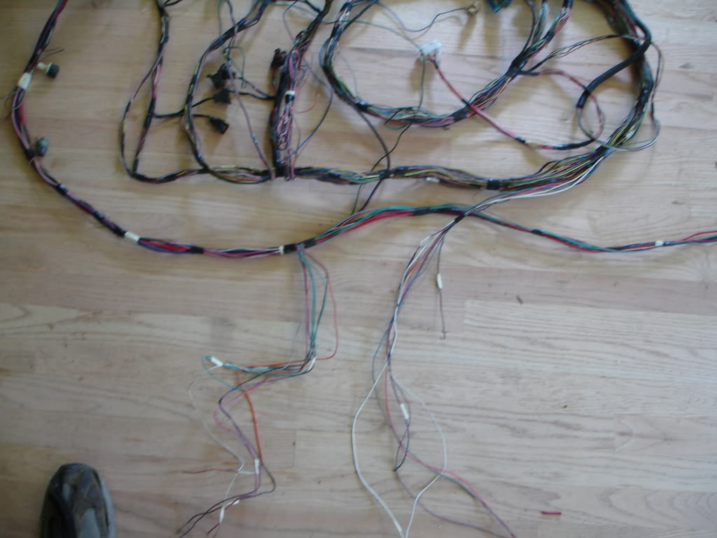
All done
The next step is to check your work and attempt to identify any problems before the harness is installed
Pop the PCM color covers off and set the multimeter to the lowest resistance setting it has. Now do a continuity test across each individual wire. Replace anything with more than 1.5ohms of resistance. This is a signal for a bad connection/wire. Several of the sensors are resistance based, so excessive resistance across lengths of wire sends false signl to the PCM and causes major problems down the road. Once everything checks out, loom it and install. Your job is done!


Junior Member
Joined: May 2008
Posts: 6
Likes: 0
From: Omaha, Ne
Car: I used to drive a 90' Formula
Engine: Had a 355tbi
Transmission: Had a 700R4
Axle/Gears: Had 2.73
Re: LT1 harness: Start to Finish
wow....i would never be able to attemp that myself....what would you charge to do that for someone


Joined: Oct 2007
Posts: 1,375
Likes: 6
From: Wyoming
Car: 1995 Formula
Engine: LT1 350
Transmission: Built 4L60e
Axle/Gears: 10 bolt, Eaton posi, 3.73's
Re: LT1 harness: Start to Finish
Jon, do you have a color to color diagram for wiring in the OBDII terminal in place of the ALDL?
Trending Topics
Thread Starter
Joined: Jun 2005
Posts: 8,122
Likes: 362
From: NC
Car: 91 Trans Am
Re: LT1 harness: Start to Finish
The OBDII wiring is not compatible with any of the OBDI stuff under your 3rd gen dash. A new connector is sent already wired in for OBDII swaps. Either cut out the old connector or ignore it forever
Member
iTrader: (5)
Joined: May 2009
Posts: 496
Likes: 0
From: Washington D.C.
Car: 1985 Z28
Engine: LT1
Transmission: T56
Axle/Gears: fourth gen 3.42
Re: LT1 harness: Start to Finish
for future reference this site has the info for 1996 LT1s that have an OBDII style port:
http://lt1swap.com/fuseblock_obd2port.html
~Steven
http://lt1swap.com/fuseblock_obd2port.html
~Steven

Joined: Dec 2002
Posts: 287
Likes: 0
From: Poconos, Pa
Car: 1984 Firebird
Engine: LT1
Transmission: T5
Axle/Gears: 3.42's
Re: LT1 harness: Start to Finish
Hey Pocket,
If I were to extend my harness so I can mount the PCM in the stock location, what gauge wire and I safely get away with?
Thanks!
If I were to extend my harness so I can mount the PCM in the stock location, what gauge wire and I safely get away with?
Thanks!
Member
iTrader: (5)
Joined: May 2009
Posts: 496
Likes: 0
From: Washington D.C.
Car: 1985 Z28
Engine: LT1
Transmission: T56
Axle/Gears: fourth gen 3.42
Re: LT1 harness: Start to Finish
i did all of my extensions with 18 gauge. relays and some other things will require 12 and 16 gauge.
~Steven
~Steven

Senior Member
Joined: Sep 2007
Posts: 599
Likes: 1
From: Long Island, NY
Car: 1992 z28
Engine: 383 LT1 in the works
Transmission: T-56 in the works
Axle/Gears: 3.73 in the works
Re: LT1 harness: Start to Finish
as long as you dont go smaller or excessively large from the original wires you are lengthening you should be good. you can get a descent crimping/stripping tool for various ga. wires which will make it easy to identify wire sizes
Supreme Member
iTrader: (10)
Joined: Oct 2007
Posts: 1,881
Likes: 2
From: Fl.
Car: 83 Trans Am / 96 Jeep XJ
Engine: 355 / 4.0 I6
Transmission: TH350 / Auto
Axle/Gears: 3.23 10-bolt / 4wd
Re: LT1 harness: Start to Finish
Lets say that I want my ECM (PCM, Computer, whatever) where the 3rd gens ac box would be (deleted ac alltogether) and considering that is where it is stored in a 4th gen, can I just mount it in that area, without having to lengthen the wires?
I have been reading your threads, and the links that you post in your threads pretty much every day, and I just confuse myself (I am easily confused lol).
How many wires in total will connect to the C100 on the thirdgens firewall?
Can I just leave the LT1 Harness connected to the engine, mount the ECM, and various grounds, then connect the various wires off of the motor to the C100, and be done with it? I plan on keeping the under-hood fuse/relay block just for the simplicity of it, and mounting it wherever it ends up.
Maybe I am over-thinking this project to death, but I still don't fully understand what exactly is going on in the pictures.
Thanks, Pocket.
Thread Starter
Joined: Jun 2005
Posts: 8,122
Likes: 362
From: NC
Car: 91 Trans Am
Re: LT1 harness: Start to Finish
You're looking for a minimal effort install, which is fine. This is the wrong thread for it
Read this thread, namely the part about wiring
https://www.thirdgen.org/forums/ltx-...questions.html
Read this thread, namely the part about wiring
https://www.thirdgen.org/forums/ltx-...questions.html
Junior Member
Joined: Aug 2010
Posts: 10
Likes: 0
From: Louisvill,KY
Car: S-10
Engine: LT1
Transmission: 4L60
Axle/Gears: 3:42
Re: LT1 harness: Start to Finish
I'm new to this site and you seem knowlegable when it comes to an lt1 harness, so of course, Ihave a question for you. I'm doing an lt swap into a first gen s-10 and I'm completely lost with all this wiring. I've got a 95 lt1 4l60 trans harness and computer and was wondering if you have a diagram of what wires to cut/keep. I'm doing away with a/c,vats,emissions,etc. I read some where that you can also delete the MAF by programing the pcm. If you can help, It would be great.
Junior Member
Joined: Jul 2009
Posts: 42
Likes: 0
From: new jersy
Car: 1991 camaro RS
Engine: LT1
Transmission: automatic
Axle/Gears: 3.25
Re: LT1 harness: Start to Finish
Im currently working on wiring my Lt1 its from a 95 corvette. I have prepared the harness from my v6 they way you specified. by the way the car is a 91. My question is when i have the pins out of the plugs that go into the computer do i need to put them back in the exact place they were you lost me on that part. I did not take anything off the Lt1 yet and it is in the car can you point me in the right direction on starting the rewiring?
Thread Starter
Joined: Jun 2005
Posts: 8,122
Likes: 362
From: NC
Car: 91 Trans Am
Re: LT1 harness: Start to Finish
The will be going back in the exact places in the end. They are removed at the start for simplicity's sake to keep from tangling and speed lengthening/shortening. Some are removed entirely in the end
Dont worry about remembering what pin does what right now. When you label each indiv circuit youll label the pins
Dont worry about remembering what pin does what right now. When you label each indiv circuit youll label the pins
Member
Joined: Sep 2007
Posts: 137
Likes: 0
From: Cali
Car: 1987 IROCZ
Engine: LT1/4 hybrid
Transmission: T56
Axle/Gears: Posi
Re: LT1 harness: Start to Finish
Hey Pocket, I'm right in the middle of modifying my '96 LT1 harness and the C100 out of my '87 IROC, and I have a couple of questions about the wires in the picture...
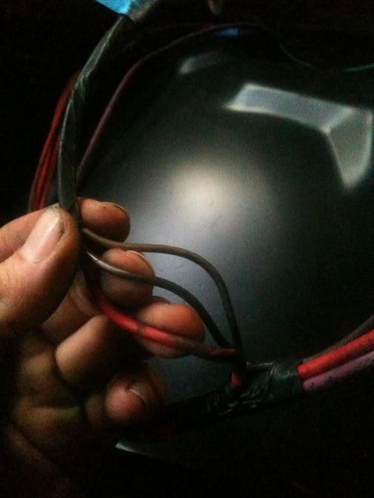
This is the connector coming from the alt. off my 305 TPI on the C100, the big red wire goes to the starter...and the brown and black ones go to the C100 socket, but where do I connect them to on my LT1 harness?
The other thing is that I cannot for the life of me figure out where the reverse light wires are...all the pin out info I can find for an '87 doesnt tell me where it comes from...any help?
Thread Starter
Joined: Jun 2005
Posts: 8,122
Likes: 362
From: NC
Car: 91 Trans Am
Re: LT1 harness: Start to Finish
Red and black wires go away. Brn alt wire from the 3rd gen harness feeds the LT1 alt. One wire versions, put a 470 ohm resistor inline and hook it up directly. Two wire versions get the resistor on the L terminal and 12v on the F terminal. Easiest way to do that is to put the resistor on L then splice the two together, then splice them to the 3rd gen wire
Back-up lights are in the C100 for original manual cars. Auto to manual conversion cars had to modify the wiring near the old auto shifter
Back-up lights are in the C100 for original manual cars. Auto to manual conversion cars had to modify the wiring near the old auto shifter
Member
Joined: Sep 2007
Posts: 137
Likes: 0
From: Cali
Car: 1987 IROCZ
Engine: LT1/4 hybrid
Transmission: T56
Axle/Gears: Posi
Re: LT1 harness: Start to Finish
Okay thanks! My alt is the single red wire on the LT1. *oh and so just a plain old radio shack resistor work I take it?*
And okay...hmm it is an original manual car...I'll have to keep on digging. I cant find any direct info regarding the pin out for an '87 manual, but from everything else I can find from '86 & '88, its the brown wire from F8 on the C100
And okay...hmm it is an original manual car...I'll have to keep on digging. I cant find any direct info regarding the pin out for an '87 manual, but from everything else I can find from '86 & '88, its the brown wire from F8 on the C100
Last edited by LT1_IROCZ_KID; Dec 17, 2010 at 10:07 PM.
Thread Starter
Joined: Jun 2005
Posts: 8,122
Likes: 362
From: NC
Car: 91 Trans Am
Re: LT1 harness: Start to Finish
Yes, any of the 470ohm resistor packs will work. I use the 1/4 watt because they're slightly cheaper
http://www.lt1swap.com/pictures/100_1594.jpg
http://www.lt1swap.com/pictures/100_1594.jpg
Member
Joined: Sep 2007
Posts: 137
Likes: 0
From: Cali
Car: 1987 IROCZ
Engine: LT1/4 hybrid
Transmission: T56
Axle/Gears: Posi
Re: LT1 harness: Start to Finish
Okay great thanks Pocket! I'll have some more questions soon I'm sure...this figuring out where the different splices go is a bit daunting!
Member
Joined: Sep 2007
Posts: 137
Likes: 0
From: Cali
Car: 1987 IROCZ
Engine: LT1/4 hybrid
Transmission: T56
Axle/Gears: Posi
Re: LT1 harness: Start to Finish
Hey Pocket, I'm stuck again! Big surprise there...so I'm having a little trouble understanding what exactly needs to be connected to the C207, and this smaller connector that has 5 wires in it and the injector power wires actually go through it, not the C207 like everything I've read says they do.
I know that coming from the LT1 harness the tach, MIL, oil pressure, injectors and various power wires that need a fuse...but I'm honestly completely lost in regards to the rest. I need lots of help! The pin out I have for the C207 isnt the same as my harness so I'm having trouble trusting the info that I have.
If someone could help me out with maybe a list of what I need to connect to the C100/C207 that would be awesome! Wiring is definitely not my thing.
Thanks!
Member
Joined: Sep 2007
Posts: 137
Likes: 0
From: Cali
Car: 1987 IROCZ
Engine: LT1/4 hybrid
Transmission: T56
Axle/Gears: Posi
Re: LT1 harness: Start to Finish
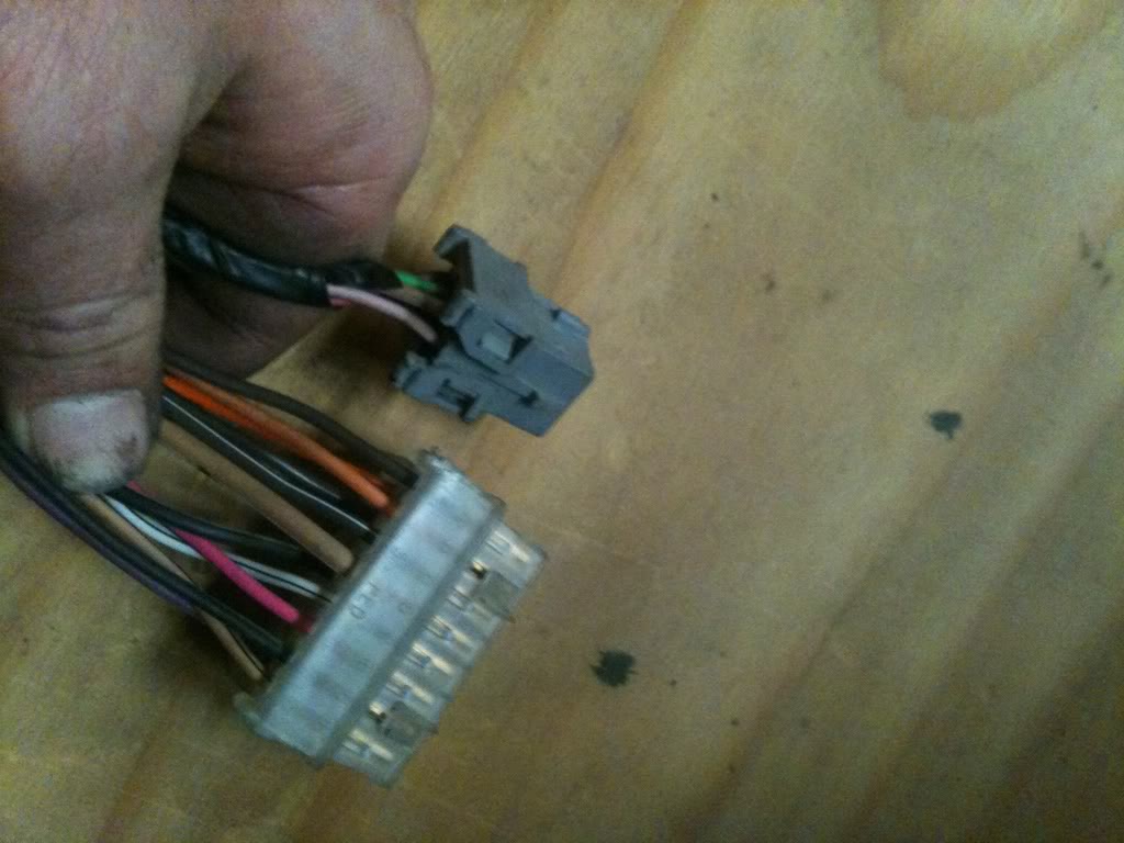
the small grey connector has the injector wires running through it, and I just traced the orange wire from socket B (that my pin out says is supposed to be pink and go to a bank of injectors) to the fuel pump relay that my wiring diagram says should be red...
another question, where exactly, if at all, is the fuel pump switch supposed to fit into all of this?...and where is the fuel pump prime connector?
Last edited by LT1_IROCZ_KID; Jan 5, 2011 at 12:39 AM.
Thread Starter
Joined: Jun 2005
Posts: 8,122
Likes: 362
From: NC
Car: 91 Trans Am
Re: LT1 harness: Start to Finish
The C207 and C221 hold various gauge and fuse wires. 86-87 dont have the pump prime test lead. The pin was assigned to the ALDL. Id suggest replacing the old flat relay for a newer style, then you can add one or leave it off. Not sure what you mean by the fuel pump switch. If its the relay bypass circuit on the oil press sender, then it can be cut out without issue
This is for 87 only with EFI from the factory. Carb cars wont have the C221 and their MIL wire will be WHT/GRN
C221
A INJ1 fuse
C Fan fuse
D INJ2 fuse
C207
C MIL
D Fuel pump 12v from relay
E ALDL B (OBDI only)
F PCM fuse
H ALDL F (OBDI only)
J ALDL M (OBDI only)
K VSS, PCM to gauge (Firebirds only)
M Cluster ground
N P/neutral
P Brake switch
Joined: Apr 2004
Posts: 556
Likes: 1
From: Houston, TX
Car: 1986 Z28
Engine: LT1
Transmission: T5 WC
Axle/Gears: 3.42 T2R
Re: LT1 harness: Start to Finish
Above is two stacks of common resistors. Each pack of 5 should set you back a whole dollar. 470ohm resistors are used for LT1 harnesses in place of the dummy light for the alternator. Firebird LS1 swaps use the 680ohm stack to boost the tach signal to their factory gauge
Odd point of fact, the Fbody LT1s use one INJ fuse, while pretty much every other engine uses two. Luckily a long runner wire is used to join the banks. Cut it free and its officially got two INJ bank fuses
Odd point of fact, the Fbody LT1s use one INJ fuse, while pretty much every other engine uses two. Luckily a long runner wire is used to join the banks. Cut it free and its officially got two INJ bank fuses
Other question is about that brown wire to the alt. First, a clarification. A 'One wire' alternator has just one wire at the plug, but two wires if you also count the one at the nut, correct? Ok, assuming that's right, the thirdgen brown wire needs to connect to the C220 red wire, got it. The third gen brown wire then goes to the thirdgen (fan) fuse block, and both thirdgen fan relays. Why the need for a resistor? Please tell me if this is right. The internal regulator turns 'on' the alt if there is a voltage difference between the bat terminal and the red/brown wire. The resistor/light is there to drop the voltage to trigger the alt.
All that said, won't the resister affect the relays? With a bulb, the light turns off and current stops flowing. With a resistor, current will constantly be flowing to it, right? So will the relays still get full volts/amps/whatever they need?
Sorry to any electrical engineers out there for butchering the terminology. I try!

I've got a '97 LT1 in an (essentially) '92 TPI. Procrastinating doing the last bit of wiring. I think I've got it all figured out. Glad I found this (and your other) thread(s), else I would have never known about the resistor trick. Thanks again!
Member
Joined: Sep 2007
Posts: 137
Likes: 0
From: Cali
Car: 1987 IROCZ
Engine: LT1/4 hybrid
Transmission: T56
Axle/Gears: Posi
Re: LT1 harness: Start to Finish
Okay that makes sense...Okay so in the C221, the wires in pins B and F don't need to be used and can be cut out? Or actually what do they go to?
Here's what I have figured out so far:
"Engine Sensor 20A fuse" **where should this go?**
-rev. lockout
-02 sensors
-MAF
"IGN 10A fuse" **and this?**
-crank pos. sensor
-coil
-coil control module
"PCM BAT 15A fuse" **can I hook this up to pin D on the C207?**
-PCM battery
-fuel pump relay power
"PCM IGN 10A fuse" **and this to pin F on the C207?**
-PCM Ignition
"Actuators 15A fuse"
-EGR vac. control solenoid valve
-Evap. emission canister purge solenoid valve
**These are the only things that say "hot in run" only, can they just be run with the "Engine sensors" that are hot in run, bulb test, or start?
C207
M cluster ground, does this just need to be grounded somewhere in the harness?
N P/neutral, where does this come from for a manual car?
P brake switch, this is the clutch switch correct?
And since I'm running an OBD2 motor, I'm thinking I should run the OBD2 ALDL wires through pins E, H, and J.

Thread Starter
Joined: Jun 2005
Posts: 8,122
Likes: 362
From: NC
Car: 91 Trans Am
Re: LT1 harness: Start to Finish
Two questions. First, is there any real advantage to running the wires to 2 INJ fuses? I noticed this when tying the LT1 harness to the thridgen fuse block. The way I read it, on the LT1, there were 3 wires that went to the LT1 20amp inj fuse. One pink (injectors) from C105, one pink (engine sensors) from C230, and one brown (engine sensors) from C230. I was planning on puttin the pink from C105 to one 3rd gen inj fuse, and the two engine sensors to the other 3rd gen inj fuse. Do you see any problems with that?
Other question is about that brown wire to the alt. First, a clarification. A 'One wire' alternator has just one wire at the plug, but two wires if you also count the one at the nut, correct? Ok, assuming that's right, the thirdgen brown wire needs to connect to the C220 red wire, got it. The third gen brown wire then goes to the thirdgen (fan) fuse block, and both thirdgen fan relays. Why the need for a resistor? Please tell me if this is right. The internal regulator turns 'on' the alt if there is a voltage difference between the bat terminal and the red/brown wire. The resistor/light is there to drop the voltage to trigger the alt.
Okay that makes sense...Okay so in the C221, the wires in pins B and F don't need to be used and can be cut out? Or actually what do they go to?
Any unused wires can be deleted. I prefer to depin and remove them entirely vs cut
Here's what I have figured out so far:
You'll have to assign these yourself. This thread goes into detail about rebuilding a harness with particular groupings of fused elements to best match the 3rd gen fuseblock without overloading any of the wiring
"Engine Sensor 20A fuse" **where should this go?**
-rev. lockout
-02 sensors
-MAF
"IGN 10A fuse" **and this?**
-crank pos. sensor
-coil
-coil control module
"PCM BAT 15A fuse" **can I hook this up to pin D on the C207?**
-PCM battery
-fuel pump relay power
No, C207 D for most cars is fuel pump 12v, meaning 12v output of the fuel relay goes through this to reach the pump. 3rd gens have a separate fuse located near the battery for the fuel pump/ECM/PCM
"PCM IGN 10A fuse" **and this to pin F on the C207?**
-PCM Ignition
[b]Yes}
"Actuators 15A fuse"
-EGR vac. control solenoid valve
-Evap. emission canister purge solenoid valve
**These are the only things that say "hot in run" only, can they just be run with the "Engine sensors" that are hot in run, bulb test, or start?
The only pieces that are not hot in run are the fuel pump and PCM batt. All others are hot in run AKA IGN 12v or switched 12v. Use the emissions common from the C100
C207
M cluster ground, does this just need to be grounded somewhere in the harness?
Ground to anything anywhere
N P/neutral, where does this come from for a manual car?
CPP
P brake switch, this is the clutch switch correct?
No, its brake switch still, but manual cars dont need it
And since I'm running an OBD2 motor, I'm thinking I should run the OBD2 ALDL wires through pins E, H, and J.
No, run OBDII wiring separate of the C207 unless you really want to reuse the short length of wiring inside the dash
Joined: Apr 2004
Posts: 556
Likes: 1
From: Houston, TX
Car: 1986 Z28
Engine: LT1
Transmission: T5 WC
Axle/Gears: 3.42 T2R
Re: LT1 harness: Start to Finish
Thanks!
Member
Joined: Sep 2007
Posts: 137
Likes: 0
From: Cali
Car: 1987 IROCZ
Engine: LT1/4 hybrid
Transmission: T56
Axle/Gears: Posi
Re: LT1 harness: Start to Finish
Great thanks so much!
Just one question with what you said about assigning some of the fuses myself, if I were to just use the old 4th gen engine bay fuse block to run these fuses in can I just hook them up directly to the power distribution block or what? The better question is how do I make one fuse switched power verses constant. Especially for the fuel pump and PCM batt.
Just one question with what you said about assigning some of the fuses myself, if I were to just use the old 4th gen engine bay fuse block to run these fuses in can I just hook them up directly to the power distribution block or what? The better question is how do I make one fuse switched power verses constant. Especially for the fuel pump and PCM batt.
Member
Joined: Sep 2007
Posts: 137
Likes: 0
From: Cali
Car: 1987 IROCZ
Engine: LT1/4 hybrid
Transmission: T56
Axle/Gears: Posi
Re: LT1 harness: Start to Finish
Actually I think I understand it now. I need to run a main relay that powers the fuel pump and PCM batt until the car is turned on, so I need to use key 12v+ as the trigger to turn on the main relay which then powers all the sensors and everything else I was talking about above...now where can I pull a key 12v+ from?
Member
Joined: Sep 2007
Posts: 137
Likes: 0
From: Cali
Car: 1987 IROCZ
Engine: LT1/4 hybrid
Transmission: T56
Axle/Gears: Posi
Re: LT1 harness: Start to Finish
The C207 and C221 hold various gauge and fuse wires. 86-87 dont have the pump prime test lead. The pin was assigned to the ALDL. Id suggest replacing the old flat relay for a newer style, then you can add one or leave it off. Not sure what you mean by the fuel pump switch. If its the relay bypass circuit on the oil press sender, then it can be cut out without issue
This is for 87 only with EFI from the factory. Carb cars wont have the C221 and their MIL wire will be WHT/GRN
C221
A INJ1 fuse
C Fan fuse
D INJ2 fuse
C207
C MIL
D Fuel pump 12v from relay
E ALDL B (OBDI only)
F PCM fuse
H ALDL F (OBDI only)
J ALDL M (OBDI only)
K VSS, PCM to gauge (Firebirds only)
M Cluster ground
N P/neutral
P Brake switch
This is for 87 only with EFI from the factory. Carb cars wont have the C221 and their MIL wire will be WHT/GRN
C221
A INJ1 fuse
C Fan fuse
D INJ2 fuse
C207
C MIL
D Fuel pump 12v from relay
E ALDL B (OBDI only)
F PCM fuse
H ALDL F (OBDI only)
J ALDL M (OBDI only)
K VSS, PCM to gauge (Firebirds only)
M Cluster ground
N P/neutral
P Brake switch
Okay so I have almost everything done, but for the C207, I'm still struggling to figure out what goes in these sockets:
A Brown wire with brown and grey commoned into it
G BLK/PPL that commons to about 5 different things, power common?
N supposed to be P/Neutral, is completely missing.
and you said use the emissions common from the C100 for my actuators fuse, is that the TAN wire that goes into a connector with a green wire coming out near the firewall? or the other connector further down with a PNK/BLK and a BLK wire?
Thanks!
Thread Starter
Joined: Jun 2005
Posts: 8,122
Likes: 362
From: NC
Car: 91 Trans Am
Re: LT1 harness: Start to Finish
A AIR solenoid. Not used
G No listing in AllData. Not used
N Automatic only. 4th gens used a CPP which was the same function and reasoning as this but almost no one uses it in a swap
C100 A6 is the emissions common 12v IGN fuse. It usually stays with the EGR connector which is the PNK/BLK and BLK pair
G No listing in AllData. Not used
N Automatic only. 4th gens used a CPP which was the same function and reasoning as this but almost no one uses it in a swap
C100 A6 is the emissions common 12v IGN fuse. It usually stays with the EGR connector which is the PNK/BLK and BLK pair
Joined: Apr 2004
Posts: 556
Likes: 1
From: Houston, TX
Car: 1986 Z28
Engine: LT1
Transmission: T5 WC
Axle/Gears: 3.42 T2R
Re: LT1 harness: Start to Finish
My situation is that I made two fuse blocks, one on with ignition, one always hot. I've put the fan brown wire on the always hot. Havn't yet started up the car after the sway, but am getting close. It is a racecar, and has a master switch that kills all power. Typically, I leave the master on for the entire race weekend, and kill it during storage (a few weeks) between races. So I don't think I'm worried about the resistor draining enough of the battery to cause it not to start. Is there something else I should be concerned about leaving the alt energize wire always on for a few days at a time?
Joined: Apr 2004
Posts: 556
Likes: 1
From: Houston, TX
Car: 1986 Z28
Engine: LT1
Transmission: T5 WC
Axle/Gears: 3.42 T2R
Re: LT1 harness: Start to Finish
Yeah, you're probably right. Was just trying to take the easy way out. Thanks. I ran a wire from the red alt wire back to the actuator fuse. Once I get it running, I'll be more tempted to clean up some of the unused LT1 wiring and emissions stuff.
Almost there... Thanks Pocket for all your posts and help topics.
Almost there... Thanks Pocket for all your posts and help topics.
Member
Joined: Sep 2007
Posts: 137
Likes: 0
From: Cali
Car: 1987 IROCZ
Engine: LT1/4 hybrid
Transmission: T56
Axle/Gears: Posi
Re: LT1 harness: Start to Finish
hey pocket so over the weekend i plugged in my LT1 swap harness and when i switch the key to the "ON" position, the fuel pump fires up as it should, but when i depress the clutch, i cannot get the starter to turn over. Its not bad as its brand new. I was thinking maybe the clutch kill switch isnt wired correctly, but all it does is complete the circuit to send the IGN signal to the starter right??
I had VATS removed from my computer and from what I understand all VATS on the ODBII LT1 does is disable the fuel pump correct? I'm a little lost!!
Thanks!!
I had VATS removed from my computer and from what I understand all VATS on the ODBII LT1 does is disable the fuel pump correct? I'm a little lost!!
Thanks!!
Member
Joined: Sep 2007
Posts: 137
Likes: 0
From: Cali
Car: 1987 IROCZ
Engine: LT1/4 hybrid
Transmission: T56
Axle/Gears: Posi
Re: LT1 harness: Start to Finish
Found the problem!! I had a bad clutch kill switch...forgot I had put the sticky dirty one in for some reason instead of the new one I had.
Thanks Pocket!!
Thanks Pocket!!
Joined: Nov 2008
Posts: 143
Likes: 6
From: Wisconsin near the 54757
Car: 1986 Camaro Z28
Engine: 385" SBC
Transmission: built out 700r4
Axle/Gears: 4th gen, 373, LSD, GIRDLE
Re: LT1 harness: Start to Finish
alright pocket. I need ya here man. I have a 1986 camaro RS, that by year/vin wasnt a 350. however before i bought it, the car was swapped to a tpi 350. when i bought it everything worked well except my turn signal light was always on. then the whole gauge cluster went dead. (apparently shorted out so i bought a new one) but before i put the new (usedd) cluster in i really need to fix the rat nest of wires that resides by the firewall on the passenger side. Also instead of a switch the fan is routed by one wire stuck into the fuse box and the radio was the same way. i pulled the trans for a rebuild and now i see that i have alot of wires grounded to the rear of the cylinder heads. I need some one to tell me which direction is up because i have no clue.
Thread Starter
Joined: Jun 2005
Posts: 8,122
Likes: 362
From: NC
Car: 91 Trans Am
Re: LT1 harness: Start to Finish
This thread is for building a harness for a LT1 engine swap. TPI problems, original or otherwise are not covered by this. Make a new thread in the TPI section
I can tell you right now, turn signal wiring has nothing to do with engine wiring so rats nest or no, its not the problem
I can tell you right now, turn signal wiring has nothing to do with engine wiring so rats nest or no, its not the problem

Junior Member
Joined: Aug 2012
Posts: 5
Likes: 0
Car: 92 camaro rs
Engine: 5.0 tbi
Re: LT1 harness: Start to Finish
Hey pocket I'm currently taking on the challenge of doin my own harness for the lt1 swap and I was just wondering am I sopuse to cut of the wires from the plastic head that's near the fuse block and label them some how or what is it that am sopuse to do

Junior Member
Joined: Feb 2014
Posts: 1
Likes: 0
From: Sheridan Arkansas
Engine: LT1
Transmission: 4l60E
Re: LT1 harness: Start to Finish
okay so im having trouble with my harness i have the bulk head wired and connected to the fire wall but as for the under hood fuse box i dont know what to do i need to know what wires on the connector go to fuses

Junior Member
Joined: Mar 2016
Posts: 1
Likes: 0
Re: LT1 harness: Start to Finish
Hello I need help I have a 97 lt1 out of a TA and my question is where can I get a copy of which wire goes where in the ecm plug I did not see a number on plug so if you can steer me in the right direction so I can print out so I can reference when reinstalling the wires I don't need the oil, a/c, temp, fans, and the fuel pump and gauge runs off the 2000 s10 ecm PLEASE HELP if you can Thanks