When you click on links to various merchants on this site and make a purchase, this can result in this site earning a commission. Affiliate programs and affiliations include, but are not limited to, the eBay Partner Network.
I've read through this entire post and I must be missing something. I'm converting an 88 305 TBI to TPI using a 91 donor including the 730 ECM and the harness. Looks easier to just repin the TBI harness but I have two questions. I understand bypassing the ESC module but I don't see any wires labeled as C & E to splice together. I assume these are two wires on the plug that goes into the distributor? Which ones?
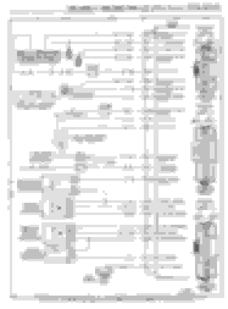
Another confusing point for me is: if both TBI and TPI use the same distributor, why does the 746 pin out diagram show a coil and the 730 pin out diagram does not show a coil? Thanks
The esc bypass connects the black to blue wire so there is a continuous wire to the ks. F9 will be the 730s input for the ks.
The letters are on the esc connector. No need to see a image of the coil. There are two wires that connect from the icm to the coil like tbi a pink and white wire.
Large gauge pink is coil power from the body harness/white is tach.
Last edited by Tuned Performance; Jan 30, 2018 at 11:54 AM.
Thank You. So, cut the Dk Blu from KS at E and Blk off the ESC at C and connect the KS DkBlu to the Blk. Then pin Blk to F9 so there is a continuous feed from F9 to the KS. Another post said to cut the ESC module off altogether and throw it away. What do I do with the PNK/Blk and Brn that I cut off the ESC?
Last edited by Midlife Cruiser; Jan 30, 2018 at 01:37 PM.
Running into questions as I'm repining. Yes I've read all of this post many times. I am converting from 88 305 TBI with Auto trans and a 165 ECM to TPI using a 91 donor TPI with 730 ECM. I am repining my 88 TBI harness for use with the 730 ecm using conversion charts from thirdgen and chevythunder. (The conversion charts from 165 to 730 are less accurate than charts for 746 to 730). I am also relying on a 1988 Camaro Electrical Diagnosis manual to verify pinouts on the 165 ecm for a VIN "E" Camaro. Ok here are two initial questions there will probably be more later.
1. The A10 pin on the 165 shows VSS Buffered to be moved to C6 on the 730. Am I correct that since my 88 has a mechanical speedo cable that I can leave this disconnected or should I go ahead and pin it to the C6 for 730?
2. The 165 to 730 charts show A11 as MAF Analog Gnd on the 165 and shows "not connected" on the 730. (I assume because the 730 doesn't use MAF) However, the Camaro Elec Diag manual shows A11 is Gnd for MAT, CTS and TPS. If I leave A11 disconnected on the 730 pins how will MAT, CTS and TPS find Gnd?
Please Help
The vss needs to be hooked up to retain iac function and tcc lockup.
Now the vss signal is hooked to pin a10 of the 88 063 ecm. It needs to be hooked to the optical input of the 730 pin c6. The memcal will need to be reprogrammed for this change as well as deleting your vats. Here is a schematic for hooking up the sensor grounds from a11 of your tbi ecm to b5 or b6 of the 730.
D2 on your tbi ecm is a dedicated map ground. This can be spliced onto b6 the cts ground.
Last edited by Tuned Performance; Feb 3, 2018 at 05:30 PM.
The vss needs to be hooked up to retain iac function and tcc lockup.
Now the vss signal is hooked to pin a10 of the 88 063 ecm. It needs to be hooked to the optical input of the 730 pin c6. The memcal will need to be reprogrammed for this change as well as deleting your vats. Here is a schematic for hooking up the sensor grounds from a11 of your tbi ecm to b5 or b6 of the 730.
D2 on your tbi ecm is a dedicated map ground. This can be spliced onto b6 the cts ground.
What other changes will need to be made to the Memcal? Who does the reprogramming? There is so much info on this site that it can be impossible to wade through it all and find the answers I need.
I edited the first part of the thread. Looks like the VSS and vats/emissions stuff comes up a lot, and apparently I should have mentioned it in 2003 or whenever I started this thread.
I'm on the final two steps to repining from 1988 165 TBI to 1991 730 TPI. The esc diagram above shows the KS has a Dk Blu wire connected to terminal E. My 165 esc connector has a white wire from the E terminal to the KS. (The 1988 Electrical Diagnosis Service manual confirms the white KS wire) I assume I should splice the white (E) and black (C) together and pin to F9?
I'll definitely do that. Have been doing that through the whole process just to be sure. Checked for continuity with meter to find the MAT, TPS, CTS and MAP connectors to find where the CTS, MAT and TPS grounds were spliced before separating the CTS GND and moving to the MAP GND. I'm getting close!
The 063 is 88 tbi vin e ecm, the pinout is the same as the 746 (89-92) tbi ecm.
My 88 305 TBI has a 165 ecm not 063. No one has answered if the 165 is the same as the 063 ecm or if there is a different pinout. I have finished the pinout and placed the harness/ecm back in the car. It won't start. If I spray starter fluid in the throttle body of the TPI it will fire until the starter fiuid is used up, so it must be a fuel supply problem. I have 12v+ at both left & right banks of the injectors from the fuse block, but can't detect any ground signal at the injectors from the ecm. I connected the green and blue injector wires (spliced to the left & right side TPI injectors) to C11 and C12 on the 730. Any ideas on why no ground signal from ecm?
After much research and help from Tuned Performance, the 88 is running good. Everything works except the Cruise Control. Looks like some more research . Thank you to Tuned Performance for his help !
Okay, have a question. After examining the "VSS speed sensor buffer box" situation, I think I have found an answer for converting TBI to TPI 7730 ECM. Using my 1990 factory service manual as reference, it appears that the only reason for the buffer box is to provide 2,000 Hz signal to TBI ECM. The 7730 (TPI) ECM uses the 4,000 hz signal directly from the VSS. So, if I run the red wire going to the buffer box instead to C1 (cruise control) of the 7730 ECM, tan wire to B11 (instrument cluster), purple wire to B9 (VSS), and yellow wire to B10 (VSS), I will have taken the buffer box out of the equation, correct?
Sorry rt66er, busy weekend. Haven't had a chance to look in to your question. Once weekend slows down I'll look at it and get back to you. Looks like "Tuned Performance" has responded to your question. You're in good hands with him!
Midlife Cruiser
Splice the right bank injector wires to 4 injector plugs. All the grounds go together to one wire, all the positives go together to the other wire. Now, splice the left bank in place to the left 4 injector plugs. If using TPI plugs, the green plugs go on right side, the red plugs go on left side.
Remove the ESC module. Cut the connector off, and splice wires C and E together. Tape up, and hide someplace neat.
Connect MAT, TPS, CTS, and IAC. Extend wires if needed.
Step 5: Repin
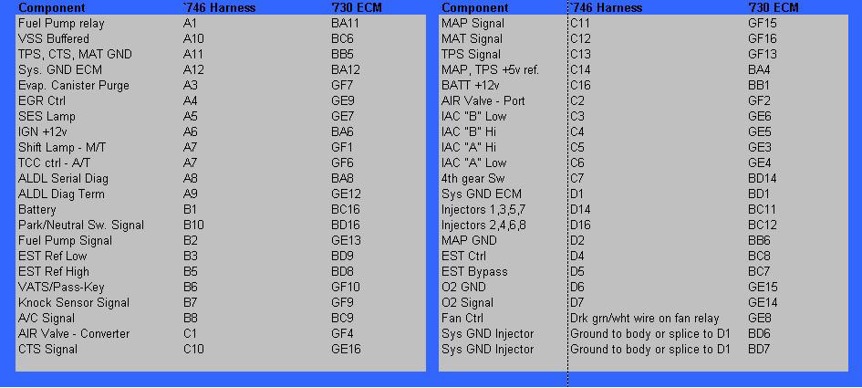
Now, repin ECM connector using following table:
Step 6: Calibration changes
At minimum, you will need to change the VSS constant from "magnetic" to "optical" because the 4-out buffer box outputs 2k pulses per mile, vs the 4k pulses per mile that the $8D calibration expects.
You may need to disable VATS, EGR, etc depending on how you did your swap.
Ok so on topic here yet a bit off topic....I�m in the midst of the tbi to tpi swap in a 91 Caprice and this thread has been very valuable, I do however have a question for anyone who has already done this.....what was used for upper rad hose when the oem Caprice fan is used.
Splice the right bank injector wires to 4 injector plugs. All the grounds go together to one wire, all the positives go together to the other wire. Now, splice the left bank in place to the left 4 injector plugs. If using TPI plugs, the green plugs go on right side, the red plugs go on left side.
Remove the ESC module. Cut the connector off, and splice wires C and E together. Tape up, and hide someplace neat.
Connect MAT, TPS, CTS, and IAC. Extend wires if needed.
Step 5: Repin
Now, repin ECM connector using following table:
Step 6: Calibration changes
At minimum, you will need to change the VSS constant from "magnetic" to "optical" because the 4-out buffer box outputs 2k pulses per mile, vs the 4k pulses per mile that the $8D calibration expects.
You may need to disable VATS, EGR, etc depending on how you did your swap.
I am having somewhat of a dilemma here (in my mind) I am in the process of swapping a TPI engine from a 91 GTA firebird to a 91 Caprice and I am getting hung up on one major issue...and that is the ECM re-pinning. I have gone through this thread over and over and I still have to ask questions....
1) I have the ECM from the firebird (1227730) which has (3) connection ports (2) black & (1) yellow.... The ECM I took out of my Caprice is a 16136965...unlike the service # as shown in the first post in this thread indicating a 1227747 ECM.... Why am I different than that?? Note I am hoping to use the wiring harness that is already in the car..with the required modifications clearly identified in this thread...
2) Since I only have 2 ports do I need to get the third connector to utilize the third connection port on the 1227730??
3) I feel stupid here in that I am having difficulties understanding the re-pinning chart/process...is there any way someone could explain the chart just a little bit more in depth What I mean by this is in the chart above it is shown for example the fuel pump relay in the 746 harness is in A1, but that wire needs to be moved to location BA11 location for the 730 harness???
Is A2 not used or is it staying as is???
The 747 is a truck ecm and does not use the mat/iat.
you will need to get the third connector they come in yellow or green.
ebay has the 3rd ecm connector or you can look in a junk yard. The 730 ecm was used in several fwd
applications.
I have it figured now...except for a couple items.
-I didn�t think the tbi 305 had a crank sensor on them....but apparently they do, so I need to figure out the pinning for that
-the wagons have a power steering pressure switch and in the repinning chart that isn�t shown so I need to figure that one out too.
The crank sensor is the distributor. As for the P/S switch, TPI engines didn't use it.
Now that I am complete this swap in my Caprice I want to add some comments here. Joe did an incredible job detailing this procedure. Kid is to him since without his info I would have been buggered.
Noteables to consider:
-throttle cable....you need a longer throttle cable and one which has the correct attachment mechanism for the throttle body
-cruise control cable. The tbi cruise control cable is different. I modified the tpi bracket to accommodate the tbi cable
-make sure the oil pressure sender is correct. I left the sender that was in the tpi engine....turns out that car had a gauge, mine only a light so I had to swap senders
-the VATS needs to be deleted from the ecm....everything will work right except the vats disables injectors unless it is deleted
-thermostat housing needs swapping to one from the 94-98 vortec. Note I am not running electric fans. Using this housing made it so own Caprice upper rad hose worked perfect
-fuel lines had to be run from the passenger side to the drivers side where the tpi lines ran to the rail.
-tpi tps connector is different than the tbi. While extending the wires take note of end connection.
Overall though it made for a or a fairly easy swap.
Hello I don�t know if I�m posting this in the right place but I�m currently working on a 89 Firebird formula with 305 lo3 swapping to a 90 l98 I have the wiring harness, computer and engine but I need some help identifying a connection by the battery which I have moved to the drivers side.Its 2 wires one red one orange in a weather tight connector it�s right before the fuel pump fuse holder any help would be greatly appreciated
Spoiler
Last edited by 89fireform; Jul 24, 2020 at 12:38 PM.
So I want to convert to tpi. I've got a 350 tpi ecm and a 305 tpi ecm with a hypertech chip. Also have a wire harness for the tpi thats in two pieces. It doesn't have the plug that goes to the drivers side under the brake booster. So confused. I was exploring the alternative to do the resin. The diagram this thread speaks of is gone. So I'm asking is ....does anyone have that diagram?
The harness can be separated out so c100 I start separate. Does your harness have the body pass through connector on the passenger side inner fender or is it a aftermarket standalone harness?
Could have been turned into a stand alone. Can always separate out you power from the starter to the interior,
alternator and exterior lighting. I think the fuel pump feed from the relay also passes through c100.
I was wanting to do that repin. First question with that repin is 1) do you have the diagram to do the repin and two can I use the 305 or 350 ecu that i have?