Sub frames (final design and build)
 05-13-2009, 11:11 PM
#51
Supreme Member

Thread Starter
iTrader: (18)
Join Date: Dec 2007
Location: Minnesota
Posts: 1,924
Likes: 0
Received 12 Likes
on
9 Posts
Car: 84 camaro, 88 trans am, 98 camaro
Engine: Modded , stock, LSX modded
Transmission: 700r4, 700r4, t-56
Axle/Gears: 327, 308, 373
Re: Sub frames (final design and build)
So i decided to now go with 2x1" tubing for the inners and centers. I will have to pick some more steel up this week. I also completely changed the center tube design. My dad had a great idea and i ran with it. It looks great on paper and at the top of the thread in MS paint. but under the car is a different story once you see how the steels going to be ran, there's to much angle in the center tubes. i will post pics later after im done building the inner tubes.
 05-13-2009, 11:12 PM
#52
Senior Member
iTrader: (2)
Join Date: Dec 2008
Location: Peoria, IL
Posts: 990
Likes: 0
Received 1 Like
on
1 Post
Car: 1988 Camaro Sport Coupe
Engine: 5.0 305 Carb'd
Transmission: 700R4
Axle/Gears: 3.23
Re: Sub frames (final design and build)
id just go with the 2X1 tubing, you have plenty of strength in the square tubing. if its not enough, then just get 11 gauge 2X1 tubing instead of the 14 gauge 2X1.5 that would make up for toughness id reckon.
05-13-2009, 11:13 PM
#53
05-19-2009, 02:41 PM
#54
Junior Member

Join Date: Apr 2009
Posts: 81
Likes: 0
Received 0 Likes
on
0 Posts
Re: Sub frames (final design and build)
When I built mine I knew that they were going to tie into the full roll cage so I did not go across the car like you are planning. I used 2X3" box and needed the ground clearance so I stuffed them up nice and tight.
 05-23-2009, 10:17 PM
#56
Supreme Member
Thread Starter
iTrader: (18)
Join Date: Dec 2007
Location: Minnesota
Posts: 1,924
Likes: 0
Received 12 Likes
on
9 Posts
Car: 84 camaro, 88 trans am, 98 camaro
Engine: Modded , stock, LSX modded
Transmission: 700r4, 700r4, t-56
Axle/Gears: 327, 308, 373
Re: Sub frames (final design and build)
Very nice!
05-23-2009, 10:21 PM
#57
Supreme Member
Thread Starter
iTrader: (18)
Join Date: Dec 2007
Location: Minnesota
Posts: 1,924
Likes: 0
Received 12 Likes
on
9 Posts
Car: 84 camaro, 88 trans am, 98 camaro
Engine: Modded , stock, LSX modded
Transmission: 700r4, 700r4, t-56
Axle/Gears: 327, 308, 373
Re: Sub frames (final design and build)
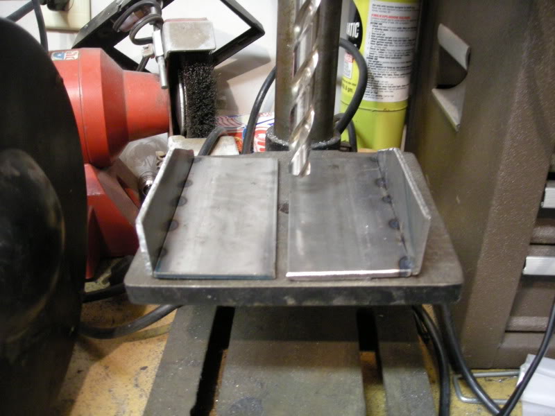
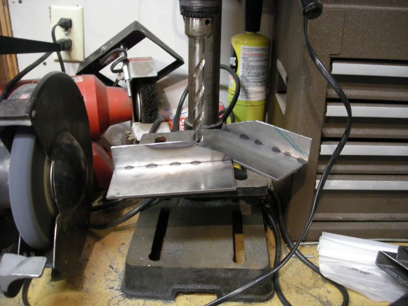
So i started making new rear brakets. 3rd times the charm i guess. these very close to the previous ones i had made.
05-23-2009, 10:25 PM
#58
Supreme Member
Thread Starter
iTrader: (18)
Join Date: Dec 2007
Location: Minnesota
Posts: 1,924
Likes: 0
Received 12 Likes
on
9 Posts
Car: 84 camaro, 88 trans am, 98 camaro
Engine: Modded , stock, LSX modded
Transmission: 700r4, 700r4, t-56
Axle/Gears: 327, 308, 373
Re: Sub frames (final design and build)
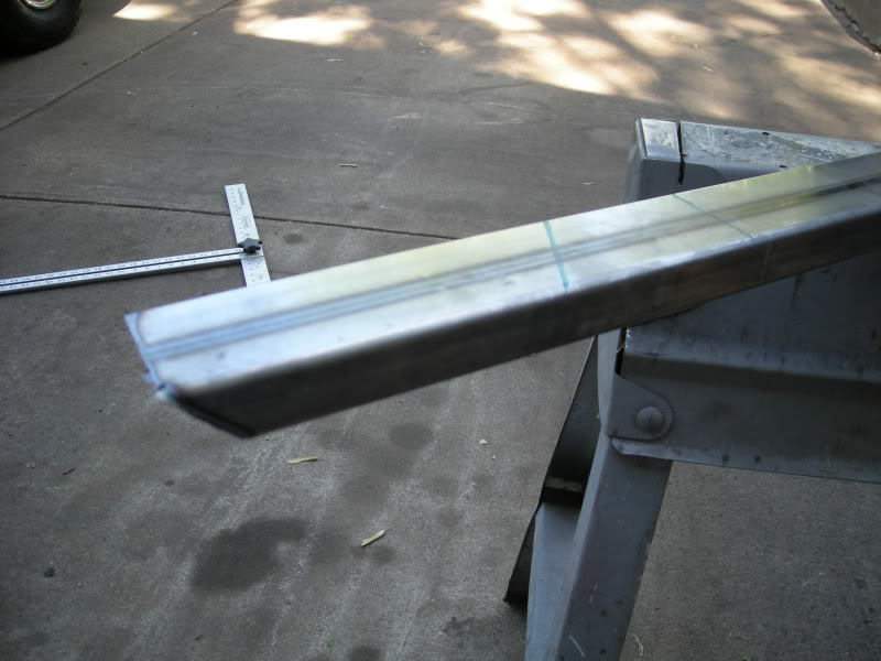
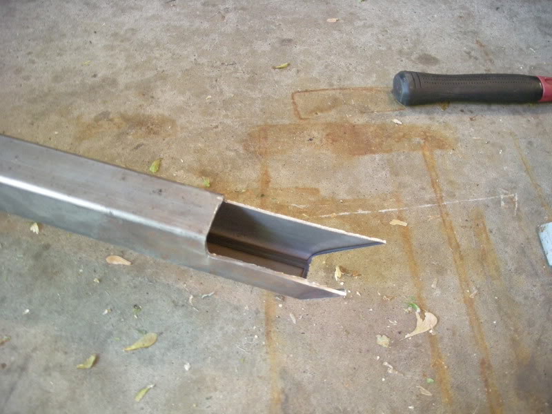
I started on the rear of the inner tubes frist. the chop saw could only cut 45� but i was still abile to cut what i needed by take some peaces off the saw and by eye balling the cut.
Last edited by FueledSoul; 05-23-2009 at 11:07 PM.
05-23-2009, 10:29 PM
#59
Supreme Member
Thread Starter
iTrader: (18)
Join Date: Dec 2007
Location: Minnesota
Posts: 1,924
Likes: 0
Received 12 Likes
on
9 Posts
Car: 84 camaro, 88 trans am, 98 camaro
Engine: Modded , stock, LSX modded
Transmission: 700r4, 700r4, t-56
Axle/Gears: 327, 308, 373
Re: Sub frames (final design and build)
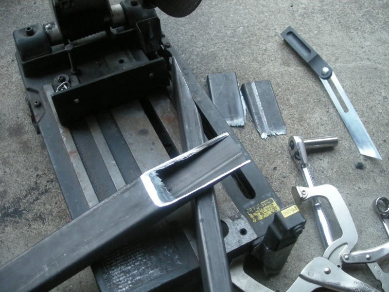
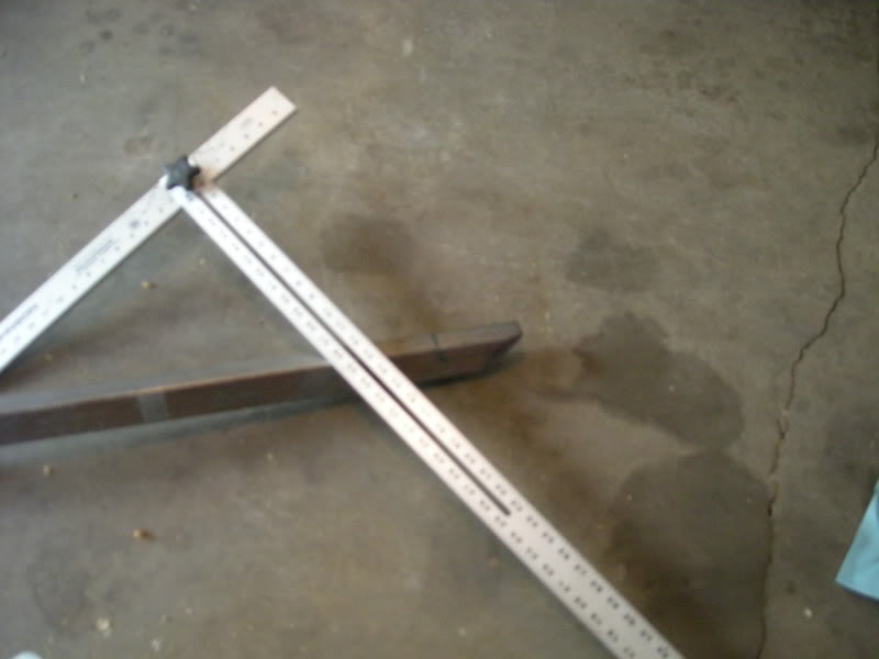
I held them in place and used a angle finder to mark where i was going to cut. i had an idea of how close i wanted to run the tubes to the floor boards too.
Last edited by FueledSoul; 05-23-2009 at 11:08 PM.
05-23-2009, 10:35 PM
#60
Supreme Member
Thread Starter
iTrader: (18)
Join Date: Dec 2007
Location: Minnesota
Posts: 1,924
Likes: 0
Received 12 Likes
on
9 Posts
Car: 84 camaro, 88 trans am, 98 camaro
Engine: Modded , stock, LSX modded
Transmission: 700r4, 700r4, t-56
Axle/Gears: 327, 308, 373
Re: Sub frames (final design and build)
Then i started to mark and cut tubes for the drivers side since it looked easier. i like to knock the easy stuff out first.
05-23-2009, 10:37 PM
#61
Supreme Member
Thread Starter
iTrader: (18)
Join Date: Dec 2007
Location: Minnesota
Posts: 1,924
Likes: 0
Received 12 Likes
on
9 Posts
Car: 84 camaro, 88 trans am, 98 camaro
Engine: Modded , stock, LSX modded
Transmission: 700r4, 700r4, t-56
Axle/Gears: 327, 308, 373
Re: Sub frames (final design and build)
.
Last edited by FueledSoul; 05-23-2009 at 11:08 PM.
05-23-2009, 10:40 PM
#62
Supreme Member
Thread Starter
iTrader: (18)
Join Date: Dec 2007
Location: Minnesota
Posts: 1,924
Likes: 0
Received 12 Likes
on
9 Posts
Car: 84 camaro, 88 trans am, 98 camaro
Engine: Modded , stock, LSX modded
Transmission: 700r4, 700r4, t-56
Axle/Gears: 327, 308, 373
Re: Sub frames (final design and build)
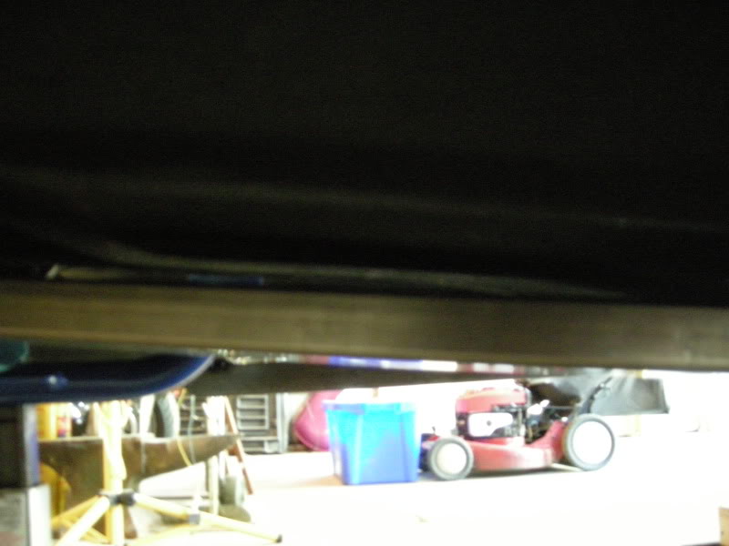
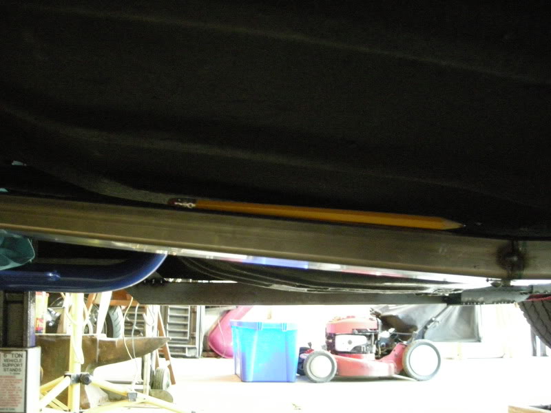
I put the diver side inner subframe up into place to see if i needed to make any other improvements and to see if i was going to have enough room for only a pencil to fit in between the floor boards and sub frames. i made my goal
Last edited by FueledSoul; 05-24-2009 at 12:23 AM.
05-23-2009, 10:44 PM
#63
Supreme Member
Thread Starter
iTrader: (18)
Join Date: Dec 2007
Location: Minnesota
Posts: 1,924
Likes: 0
Received 12 Likes
on
9 Posts
Car: 84 camaro, 88 trans am, 98 camaro
Engine: Modded , stock, LSX modded
Transmission: 700r4, 700r4, t-56
Axle/Gears: 327, 308, 373
Re: Sub frames (final design and build)
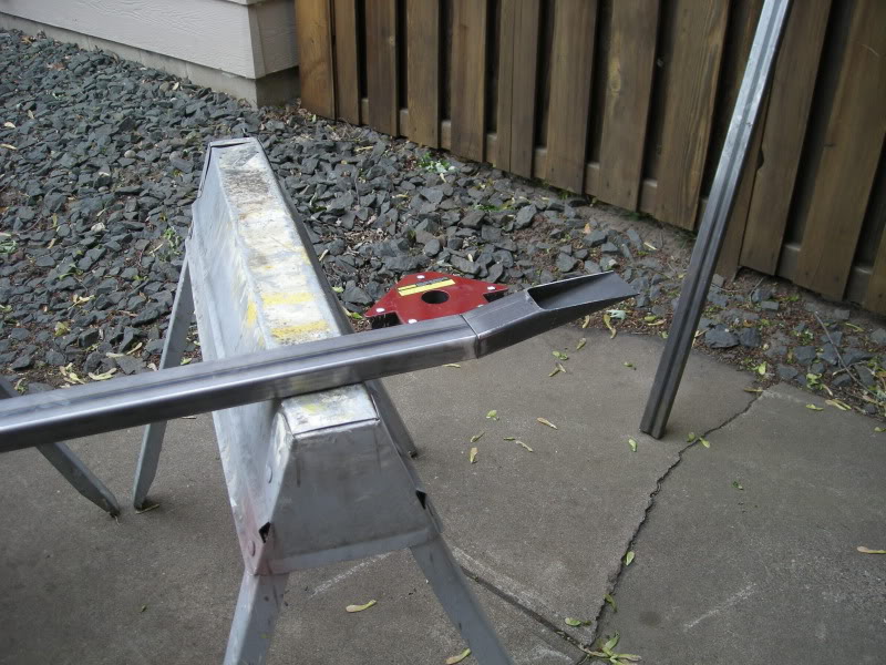
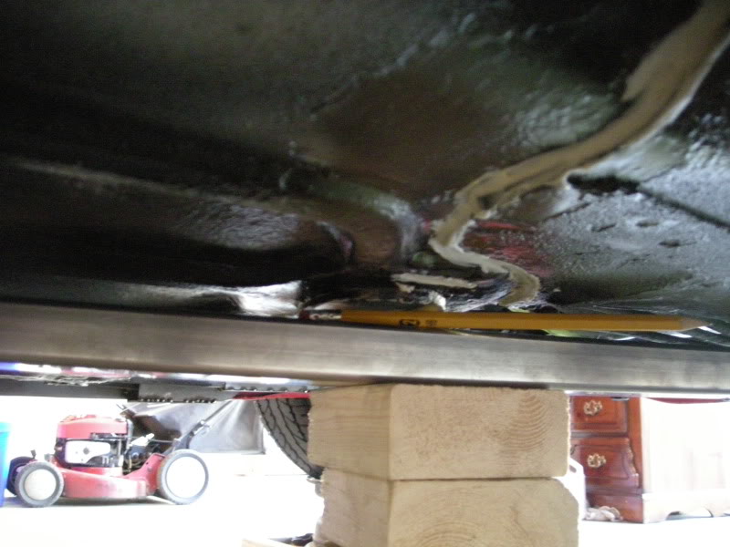
Next i start on the passenger side. i followed the contours the best i could with square tubing and they turned out great.
Last edited by FueledSoul; 05-23-2009 at 11:16 PM.
05-23-2009, 10:50 PM
#64
Supreme Member
Thread Starter
iTrader: (18)
Join Date: Dec 2007
Location: Minnesota
Posts: 1,924
Likes: 0
Received 12 Likes
on
9 Posts
Car: 84 camaro, 88 trans am, 98 camaro
Engine: Modded , stock, LSX modded
Transmission: 700r4, 700r4, t-56
Axle/Gears: 327, 308, 373
Re: Sub frames (final design and build)
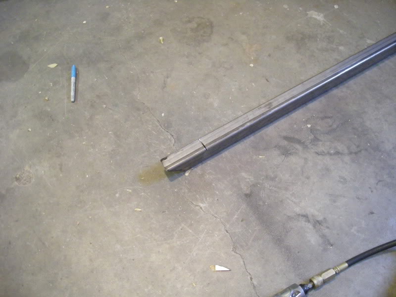
Here they are done. i still have a few things to tweak.
05-23-2009, 10:52 PM
#65
Supreme Member
Thread Starter
iTrader: (18)
Join Date: Dec 2007
Location: Minnesota
Posts: 1,924
Likes: 0
Received 12 Likes
on
9 Posts
Car: 84 camaro, 88 trans am, 98 camaro
Engine: Modded , stock, LSX modded
Transmission: 700r4, 700r4, t-56
Axle/Gears: 327, 308, 373
Re: Sub frames (final design and build)
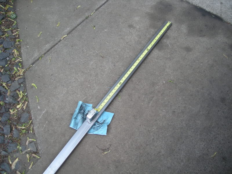
i used 16ft of tubing to make both and still had some small scrap left over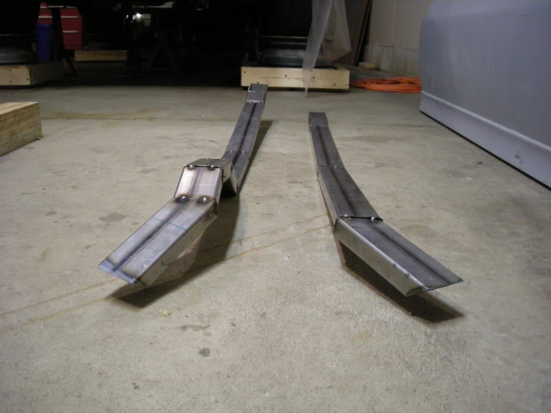
Last edited by FueledSoul; 05-23-2009 at 11:17 PM.
05-23-2009, 10:59 PM
#66
Supreme Member
Thread Starter
iTrader: (18)
Join Date: Dec 2007
Location: Minnesota
Posts: 1,924
Likes: 0
Received 12 Likes
on
9 Posts
Car: 84 camaro, 88 trans am, 98 camaro
Engine: Modded , stock, LSX modded
Transmission: 700r4, 700r4, t-56
Axle/Gears: 327, 308, 373
Re: Sub frames (final design and build)
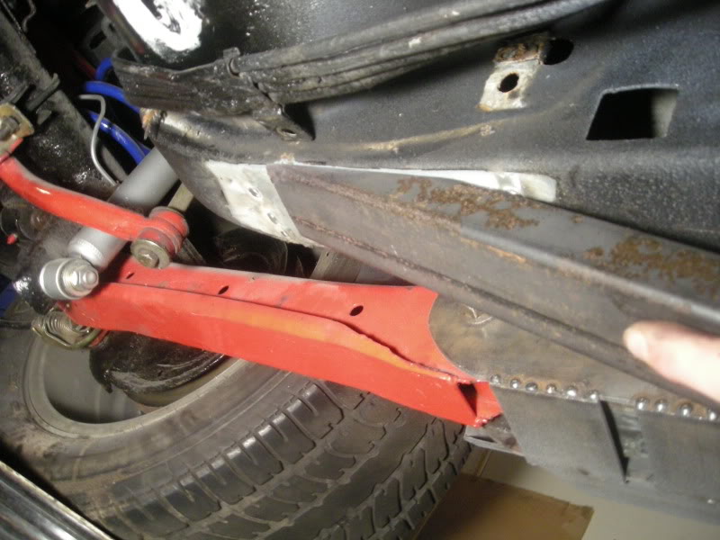
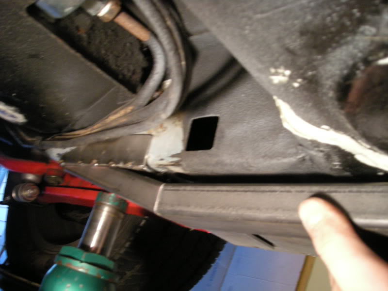
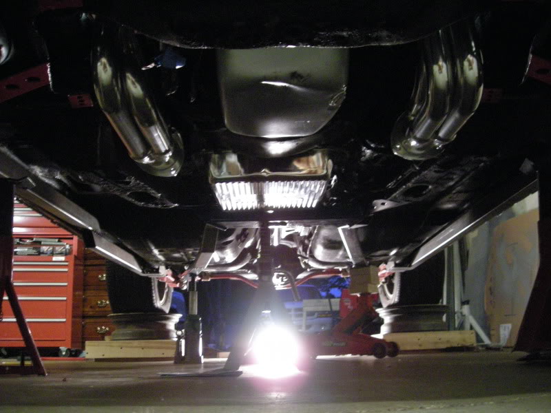
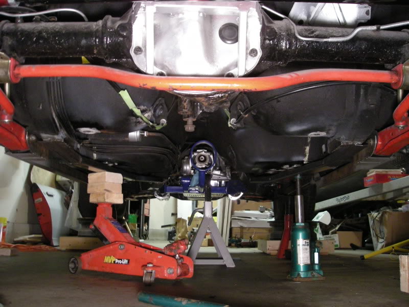
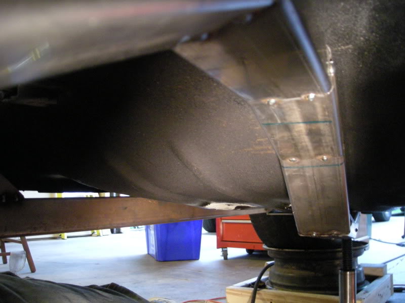
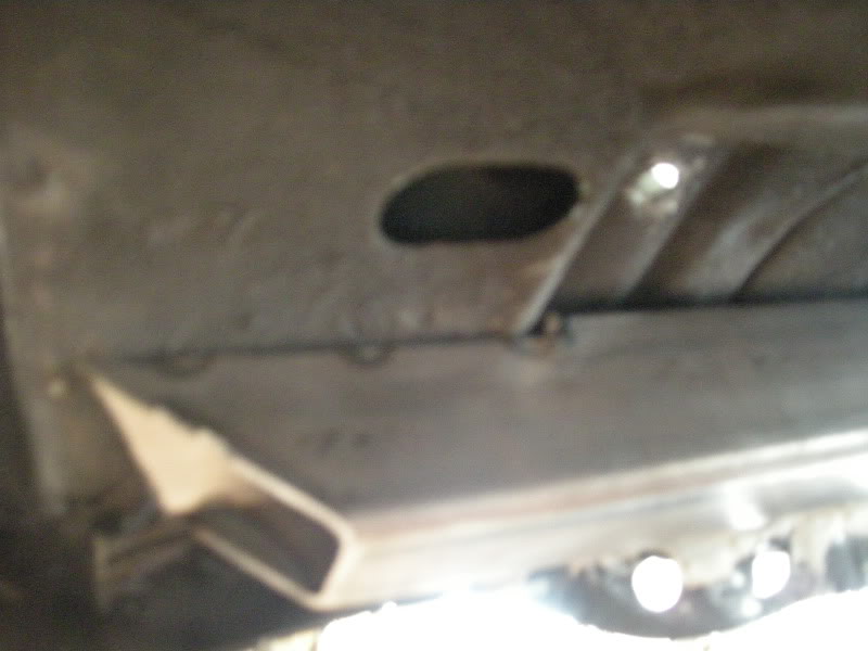
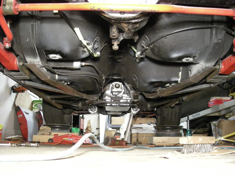
Heres some shots of them under the car but not tacked to the front and rear plates yet.
I used the drain hole pulgs as a gide along with some other things and make sure both were identicaly ran other then the bends up and down bends i had to make.
I used the drain hole pulgs as a gide along with some other things and make sure both were identicaly ran other then the bends up and down bends i had to make.
Last edited by FueledSoul; 05-23-2009 at 11:18 PM.
05-23-2009, 11:11 PM
#67
Supreme Member
iTrader: (7)
Join Date: Jun 2008
Location: Minnesota
Posts: 1,468
Likes: 0
Received 0 Likes
on
0 Posts
Car: 89 IROC-Z
Engine: 370 LSX, LS3 Top End
Transmission: Built T-56
Axle/Gears: 9" Aluminum Center 3.89's
Re: Sub frames (final design and build)
Now those are different!! In a good way!!
05-24-2009, 11:36 AM
#68
Supreme Member
iTrader: (14)
Join Date: Aug 2006
Location: Central NJ
Posts: 12,651
Likes: 0
Received 46 Likes
on
44 Posts
Car: 86 Trans Am, 92 Firebird
Engine: 408 sbc, 3.1L of raw power
Transmission: TKO600, T5
Axle/Gears: Moser 9", 3:70 trutac, 3:23 torsion
Re: Sub frames (final design and build)
they look like alston SFC's, but square! Cool deal, but is all the extra weight worth it?
05-24-2009, 12:12 PM
#69
Senior Member

Join Date: Jun 2008
Location: Norfolk VA
Posts: 1,298
Likes: 0
Received 2 Likes
on
2 Posts
Car: 85 Camaro IROC
Engine: 5.7 TPI
Transmission: 700-R4
Axle/Gears: open rear, 3.42 gears
Re: Sub frames (final design and build)
he used thinner 14 ga metal vs 11 gauge for that reason.
besides, at most we are talking about 30# over a comparable store bought sfc design that is much less stiff.
besides that... the weight is below the GC of the car, so it helps to bring the CG down, which is good.
all in all, id say that it was worth it
besides, at most we are talking about 30# over a comparable store bought sfc design that is much less stiff.
besides that... the weight is below the GC of the car, so it helps to bring the CG down, which is good.
all in all, id say that it was worth it
05-24-2009, 02:12 PM
#70
Re: Sub frames (final design and build)
looks good. dont the welded points create weak points? i always thought using once peice of tubing is stronger than something of smaller peices welded together. still tho they look good. nice job
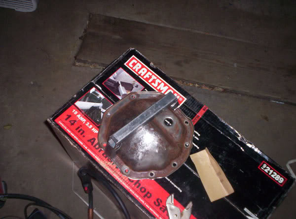
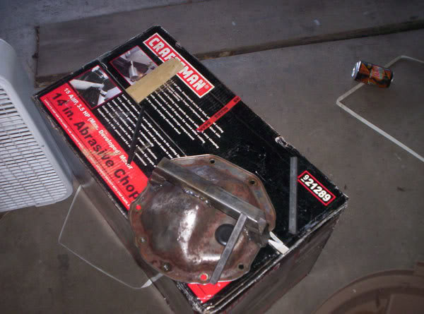
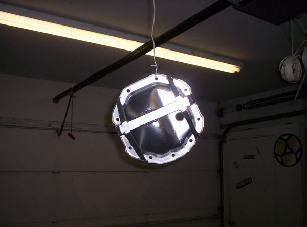
can u post pics of that diff cover? lol u look like u did alil reinforcing to that stock steel one. at first i thought it was an aluminum support girdle but its clearly not.
keep up the good work! did u end up boxing the perimeter SFC? or just leaving it hollow?
can u post pics of that diff cover? lol u look like u did alil reinforcing to that stock steel one. at first i thought it was an aluminum support girdle but its clearly not.
keep up the good work! did u end up boxing the perimeter SFC? or just leaving it hollow?
05-24-2009, 02:21 PM
#71
Supreme Member
Thread Starter
iTrader: (18)
Join Date: Dec 2007
Location: Minnesota
Posts: 1,924
Likes: 0
Received 12 Likes
on
9 Posts
Car: 84 camaro, 88 trans am, 98 camaro
Engine: Modded , stock, LSX modded
Transmission: 700r4, 700r4, t-56
Axle/Gears: 327, 308, 373
Re: Sub frames (final design and build)
looks good. dont the welded points create weak points? i always thought using once peice of tubing is stronger than something of smaller peices welded together. still tho they look good. nice job
can u post pics of that diff cover? lol u look like u did alil reinforcing to that stock steel one. at first i thought it was an aluminum support girdle but its clearly not.
keep up the good work
can u post pics of that diff cover? lol u look like u did alil reinforcing to that stock steel one. at first i thought it was an aluminum support girdle but its clearly not.
keep up the good work
yea i reinforced mine. its definitely not like the ones that incorporate the mains. but if anything it will add some rigidity to the housing .
 05-24-2009, 02:44 PM
#72
Supreme Member
Thread Starter
iTrader: (18)
Join Date: Dec 2007
Location: Minnesota
Posts: 1,924
Likes: 0
Received 12 Likes
on
9 Posts
Car: 84 camaro, 88 trans am, 98 camaro
Engine: Modded , stock, LSX modded
Transmission: 700r4, 700r4, t-56
Axle/Gears: 327, 308, 373
Re: Sub frames (final design and build)
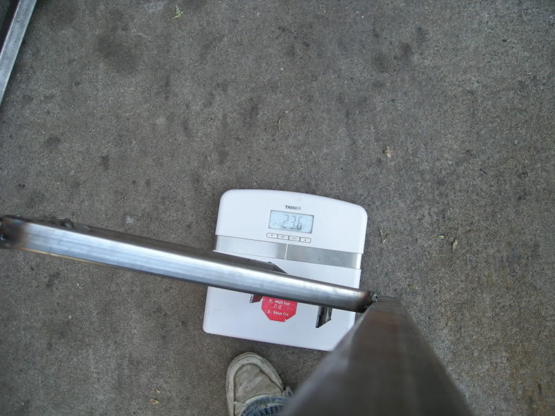
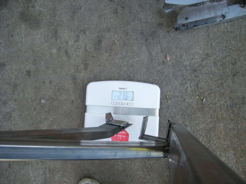
Anyway back to the subframes.
The
14ga 2x1" rectangular tubing is 1.600 Weight per lineal foor
There was 94" of tubing used to make both inner subframes.
= 12.53 lbs total weight
The
14ga 2.25" rectangular tubing is 1.882 Weight per lineal foor
There was 124" of tubing used to make both outter subframes.
= 19.45 total weight
(combined total weight so far 31.98 lbs)
Here is how they look under the car now.
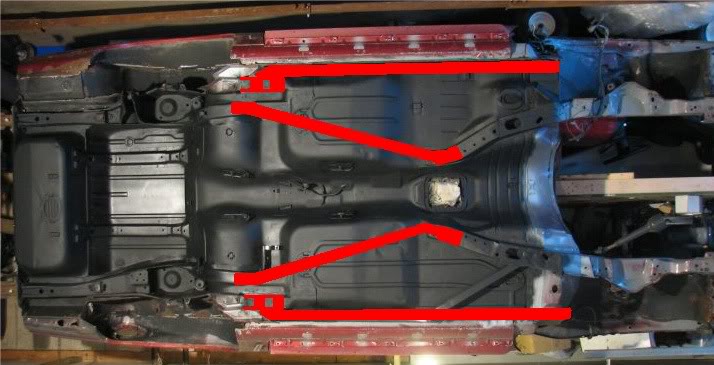
I plan to tie both inner and outer sub frames together like this.
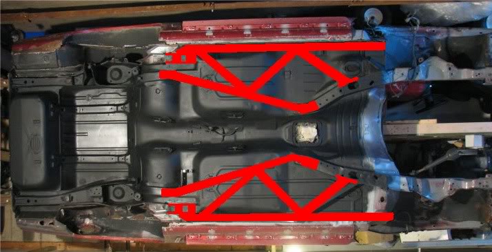
The
14ga 2x1" rectangular tubing is 1.600 Weight per lineal foor
There was 94" of tubing used to make both inner subframes.
= 12.53 lbs total weight
The
14ga 2.25" rectangular tubing is 1.882 Weight per lineal foor
There was 124" of tubing used to make both outter subframes.
= 19.45 total weight
(combined total weight so far 31.98 lbs)
Here is how they look under the car now.
I plan to tie both inner and outer sub frames together like this.
05-24-2009, 02:51 PM
#73
Banned
iTrader: (12)
Join Date: Jul 1999
Location: Bertram (outside Austin), TX
Posts: 12,212
Likes: 0
Received 10 Likes
on
10 Posts
Car: 87 GTA
Engine: L98
Transmission: 700R4
Axle/Gears: Dana M78 3.27 posi
Re: Sub frames (final design and build)
Did you make a wooden buck after finishing them, before installing them, so that you could duplicate & sell some more?
05-24-2009, 08:27 PM
#74
Senior Member
Join Date: Jun 2008
Location: Norfolk VA
Posts: 1,298
Likes: 0
Received 2 Likes
on
2 Posts
Car: 85 Camaro IROC
Engine: 5.7 TPI
Transmission: 700-R4
Axle/Gears: open rear, 3.42 gears
Re: Sub frames (final design and build)
you know, fueled soul, you could go into business with this.
i had (and still have) a friend that makes custom longboard skateboards.
he sold mostly to guys on campus and had a sweet little side job going.
when he graduated last semester, he got a small business license, and is working on a patent for a downhill truck design.
he never thought that his little hobby would blossom into a business, but it has...
the point of all this is...
dont sell yourself short.
you clearly have some fabrication talent and creativity.
there is a definite niche for thirdgen camaro parts that are affordable and well thought out.
if you were to sell your subframe connectors, i'd probably buy a pair, and if they were affordably priced (less than $225) id buy them for sure.
you should think about it.
05-25-2009, 05:49 AM
#76
Supreme Member
Thread Starter
iTrader: (18)
Join Date: Dec 2007
Location: Minnesota
Posts: 1,924
Likes: 0
Received 12 Likes
on
9 Posts
Car: 84 camaro, 88 trans am, 98 camaro
Engine: Modded , stock, LSX modded
Transmission: 700r4, 700r4, t-56
Axle/Gears: 327, 308, 373
Re: Sub frames (final design and build)
you know, fueled soul, you could go into business with this.
i had (and still have) a friend that makes custom longboard skateboards.
he sold mostly to guys on campus and had a sweet little side job going.
when he graduated last semester, he got a small business license, and is working on a patent for a downhill truck design.
he never thought that his little hobby would blossom into a business, but it has...
the point of all this is...
dont sell yourself short.
you clearly have some fabrication talent and creativity.
there is a definite niche for thirdgen camaro parts that are affordable and well thought out.
if you were to sell your subframe connectors, i'd probably buy a pair, and if they were affordably priced (less than $225) id buy them for sure.
you should think about it.
i had (and still have) a friend that makes custom longboard skateboards.
he sold mostly to guys on campus and had a sweet little side job going.
when he graduated last semester, he got a small business license, and is working on a patent for a downhill truck design.
he never thought that his little hobby would blossom into a business, but it has...
the point of all this is...
dont sell yourself short.
you clearly have some fabrication talent and creativity.
there is a definite niche for thirdgen camaro parts that are affordable and well thought out.
if you were to sell your subframe connectors, i'd probably buy a pair, and if they were affordably priced (less than $225) id buy them for sure.
you should think about it.
your compliments are very much appreciated. i have thought about it but id really have to think about it some more. But before i started putting this together and building it i kinda already knew that there was possibility people would be interested in my designed subframes. I could reproduce them, id ovisously make them better and improve upon somethings. . .
Its a real possibility and all think about it more.
05-25-2009, 08:34 PM
#77
Senior Member
Join Date: Jun 2008
Location: Norfolk VA
Posts: 1,298
Likes: 0
Received 2 Likes
on
2 Posts
Car: 85 Camaro IROC
Engine: 5.7 TPI
Transmission: 700-R4
Axle/Gears: open rear, 3.42 gears
Re: Sub frames (final design and build)
one thing i would consider is the strength of the "curved" piece you made.
other than that, you have a really good design
other than that, you have a really good design
05-25-2009, 08:45 PM
#78
Supreme Member

Re: Sub frames (final design and build)
Thanks man! yea im going to cap the ends i knew someone would ask about that haha, its just not on the top of my list. i want to get everying to where i want it then come back cap the ends and fully weld it off the car. The floor board idea you have is great. but i dont plan to do that.
Looks good. Always happy to see someone just go buy some material and figure it out instead of always posting the same silly questions over and over again. I haven't been posting here much lately again because it's always the same stuff over and over again.
Good job.
Gonna coat'm with bedliner when you're done? I'm not following your design just yet until I see some more of it. From the pictures it kind've looks like you are building them to be bolted in place?
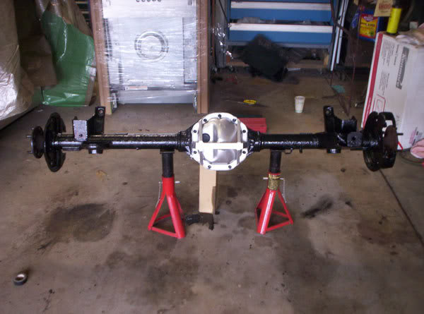
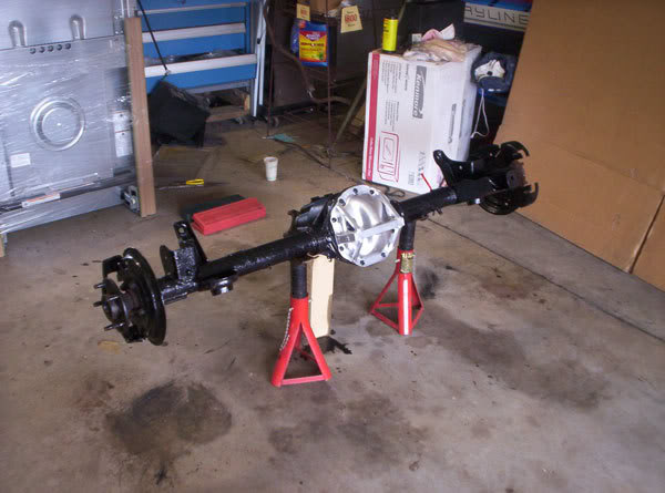
EDIT: After looking at the pics again looks like I'm seeing it wrong. The bolts I saw were for your rear suspension. Is that the stock setup or did you go with something else?
Mathius
05-26-2009, 09:24 PM
#79
Supreme Member
Thread Starter
iTrader: (18)
Join Date: Dec 2007
Location: Minnesota
Posts: 1,924
Likes: 0
Received 12 Likes
on
9 Posts
Car: 84 camaro, 88 trans am, 98 camaro
Engine: Modded , stock, LSX modded
Transmission: 700r4, 700r4, t-56
Axle/Gears: 327, 308, 373
Re: Sub frames (final design and build)
05-26-2009, 09:32 PM
#80
Senior Member
Join Date: Jun 2008
Location: Norfolk VA
Posts: 1,298
Likes: 0
Received 2 Likes
on
2 Posts
Car: 85 Camaro IROC
Engine: 5.7 TPI
Transmission: 700-R4
Axle/Gears: open rear, 3.42 gears
Re: Sub frames (final design and build)
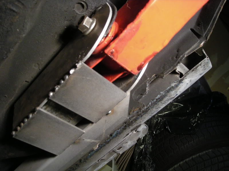
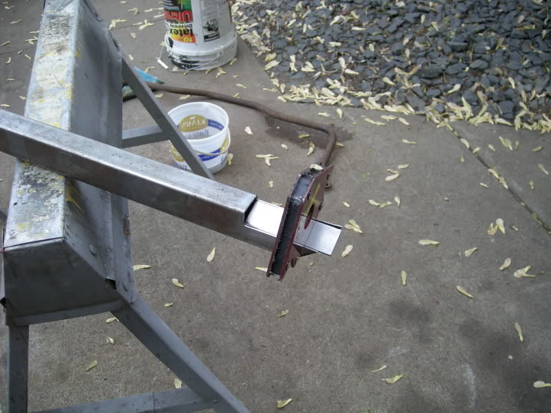
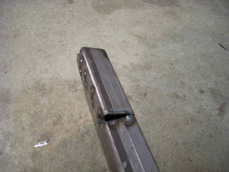
the curved piece with the bolts attaches to the rear LCA mounts so that the subframe can be bolted up for easy welding and extra strength at the joint.
unless thats not what you were talking about
unless thats not what you were talking about
05-26-2009, 09:35 PM
#81
Supreme Member
Thread Starter
iTrader: (18)
Join Date: Dec 2007
Location: Minnesota
Posts: 1,924
Likes: 0
Received 12 Likes
on
9 Posts
Car: 84 camaro, 88 trans am, 98 camaro
Engine: Modded , stock, LSX modded
Transmission: 700r4, 700r4, t-56
Axle/Gears: 327, 308, 373
Re: Sub frames (final design and build)
Looks good. Always happy to see someone just go buy some material and figure it out instead of always posting the same silly questions over and over again. I haven't been posting here much lately again because it's always the same stuff over and over again.
Good job.
Gonna coat'm with bedliner when you're done? I'm not following your design just yet until I see some more of it. From the pictures it kind've looks like you are building them to be bolted in place?
I built them to swing into place from the rear LCA's. i can take them off and put them back on so everything fits like it was once the inners and outers are tied together with the center tubes. then i can take them off and fully weld each place then bolt them back in and swing them into place so nothing will shift or move im using the rear LCA bolts as a gide for fitment for the intire subframes. just makes it simple, i planned it like that from the beginning
EDIT: After looking at the pics again looks like I'm seeing it wrong. The bolts I saw were for your rear suspension. Is that the stock setup or did you go with something else?
Last edited by FueledSoul; 05-26-2009 at 09:53 PM.
 05-26-2009, 09:41 PM
#83
Supreme Member
Thread Starter
iTrader: (18)
Join Date: Dec 2007
Location: Minnesota
Posts: 1,924
Likes: 0
Received 12 Likes
on
9 Posts
Car: 84 camaro, 88 trans am, 98 camaro
Engine: Modded , stock, LSX modded
Transmission: 700r4, 700r4, t-56
Axle/Gears: 327, 308, 373
Re: Sub frames (final design and build)
i was talking about something else
05-26-2009, 09:47 PM
#84
Senior Member
Join Date: Jun 2008
Location: Norfolk VA
Posts: 1,298
Likes: 0
Received 2 Likes
on
2 Posts
Car: 85 Camaro IROC
Engine: 5.7 TPI
Transmission: 700-R4
Axle/Gears: open rear, 3.42 gears
Re: Sub frames (final design and build)
sorry, not you, matius
i guess thats what the quote button is for lol
EDIT: After looking at the pics again looks like I'm seeing it wrong. The bolts I saw were for your rear suspension. Is that the stock setup or did you go with something else?
the curved piece with the bolts attaches to the rear LCA mounts so that the subframe can be bolted up for easy welding and extra strength at the joint.
unless thats not what you were talking about
unless thats not what you were talking about
05-26-2009, 09:52 PM
#85
Supreme Member
Thread Starter
iTrader: (18)
Join Date: Dec 2007
Location: Minnesota
Posts: 1,924
Likes: 0
Received 12 Likes
on
9 Posts
Car: 84 camaro, 88 trans am, 98 camaro
Engine: Modded , stock, LSX modded
Transmission: 700r4, 700r4, t-56
Axle/Gears: 327, 308, 373
Re: Sub frames (final design and build)
I built them to swing into place from the rear LCA's. i can take them off and put them back on so everything fits like it was once the inners and outers are tied together with the center tubes. then i can take them off and fully weld each place then bolt them back in and swing them into place so nothing will shift or move im using the rear LCA bolts as a gide for fitment for the intire subframes. just makes it simple, i planned it like that from the beginning
05-27-2009, 10:36 PM
#87
Supreme Member
Thread Starter
iTrader: (18)
Join Date: Dec 2007
Location: Minnesota
Posts: 1,924
Likes: 0
Received 12 Likes
on
9 Posts
Car: 84 camaro, 88 trans am, 98 camaro
Engine: Modded , stock, LSX modded
Transmission: 700r4, 700r4, t-56
Axle/Gears: 327, 308, 373
Re: Sub frames (final design and build)
 05-27-2009, 10:39 PM
#88
Supreme Member
Thread Starter
iTrader: (18)
Join Date: Dec 2007
Location: Minnesota
Posts: 1,924
Likes: 0
Received 12 Likes
on
9 Posts
Car: 84 camaro, 88 trans am, 98 camaro
Engine: Modded , stock, LSX modded
Transmission: 700r4, 700r4, t-56
Axle/Gears: 327, 308, 373
Re: Sub frames (final design and build)
So i re-worked the passenger inner sub frame a bit. I wanted to tuck it up tighter and have it match the drivers side floor board to sub frame gap.
Last edited by FueledSoul; 05-27-2009 at 10:48 PM.
05-31-2009, 08:41 PM
#89
Supreme Member
Thread Starter
iTrader: (18)
Join Date: Dec 2007
Location: Minnesota
Posts: 1,924
Likes: 0
Received 12 Likes
on
9 Posts
Car: 84 camaro, 88 trans am, 98 camaro
Engine: Modded , stock, LSX modded
Transmission: 700r4, 700r4, t-56
Axle/Gears: 327, 308, 373
Re: Sub frames (final design and build)
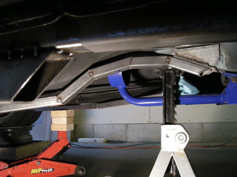
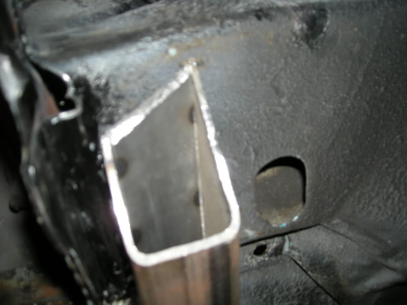
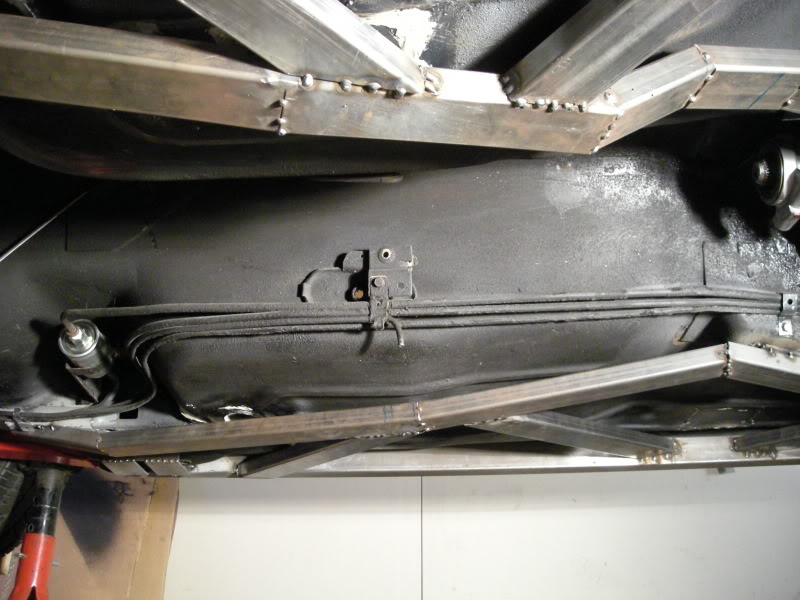
So i finally got around to the the outer sub frames again, i had to notch and modifie them so they would touch the front sub frames 360�. Why? . . . well because now these sit 100% flush and can be welded 360� I have built ever peace this way. I believe 360� of weld around the factory sub frames are better then wimpy lines of welds.
I have to prep a few areas, but I'm almost ready to tack down the inner and outer sub frames and start on the center tubes!!!
Passenger side
I have to prep a few areas, but I'm almost ready to tack down the inner and outer sub frames and start on the center tubes!!!
Passenger side
05-31-2009, 08:43 PM
#90
Supreme Member
Thread Starter
iTrader: (18)
Join Date: Dec 2007
Location: Minnesota
Posts: 1,924
Likes: 0
Received 12 Likes
on
9 Posts
Car: 84 camaro, 88 trans am, 98 camaro
Engine: Modded , stock, LSX modded
Transmission: 700r4, 700r4, t-56
Axle/Gears: 327, 308, 373
Re: Sub frames (final design and build)
 05-31-2009, 08:44 PM
#91
Supreme Member
Thread Starter
iTrader: (18)
Join Date: Dec 2007
Location: Minnesota
Posts: 1,924
Likes: 0
Received 12 Likes
on
9 Posts
Car: 84 camaro, 88 trans am, 98 camaro
Engine: Modded , stock, LSX modded
Transmission: 700r4, 700r4, t-56
Axle/Gears: 327, 308, 373
Re: Sub frames (final design and build)
Drivers side. i need to clean both the left and right sides up but i will do that after the center tubes are done and the sub frames are off the car
05-31-2009, 09:00 PM
#92
Banned
iTrader: (12)
Join Date: Jul 1999
Location: Bertram (outside Austin), TX
Posts: 12,212
Likes: 0
Received 10 Likes
on
10 Posts
Car: 87 GTA
Engine: L98
Transmission: 700R4
Axle/Gears: Dana M78 3.27 posi
Re: Sub frames (final design and build)
Cutting across them was no doubt the easy part...But how did you make the lengthwise cuts? Bandsaw?
You gonna make notches at each point along them, as the floor drops to keep them touching 110%?
You gonna make notches at each point along them, as the floor drops to keep them touching 110%?
05-31-2009, 09:54 PM
#93
Supreme Member
Thread Starter
iTrader: (18)
Join Date: Dec 2007
Location: Minnesota
Posts: 1,924
Likes: 0
Received 12 Likes
on
9 Posts
Car: 84 camaro, 88 trans am, 98 camaro
Engine: Modded , stock, LSX modded
Transmission: 700r4, 700r4, t-56
Axle/Gears: 327, 308, 373
Re: Sub frames (final design and build)
You mean the notches i made? I used a cut off wheel. oh, no not the floor boards just the ends of the sub frame connectors to the factory frame rails them self. sorry if that was confusing
Last edited by FueledSoul; 05-31-2009 at 09:58 PM.
06-09-2009, 10:55 PM
#94
Supreme Member
Thread Starter
iTrader: (18)
Join Date: Dec 2007
Location: Minnesota
Posts: 1,924
Likes: 0
Received 12 Likes
on
9 Posts
Car: 84 camaro, 88 trans am, 98 camaro
Engine: Modded , stock, LSX modded
Transmission: 700r4, 700r4, t-56
Axle/Gears: 327, 308, 373
Re: Sub frames (final design and build)
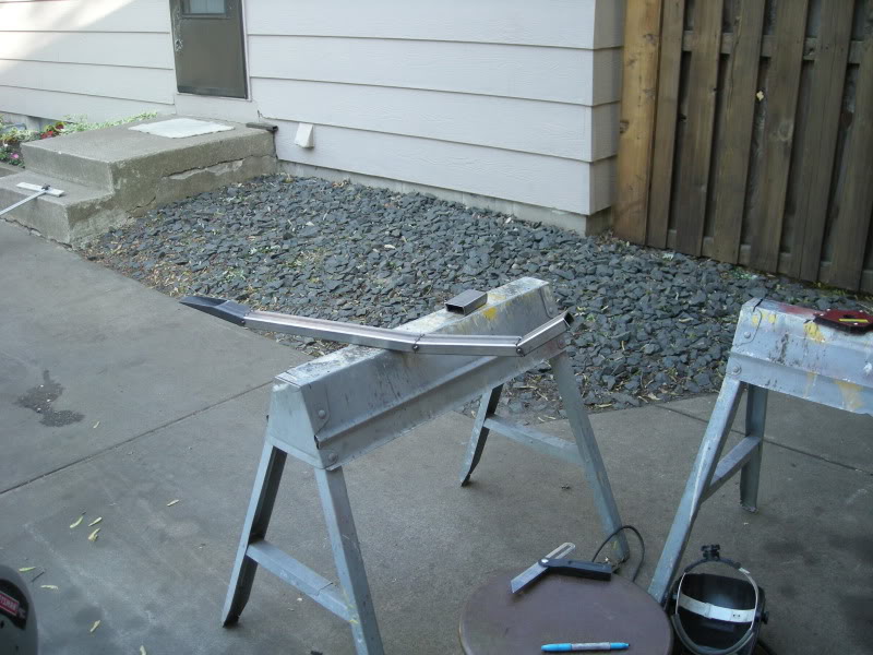
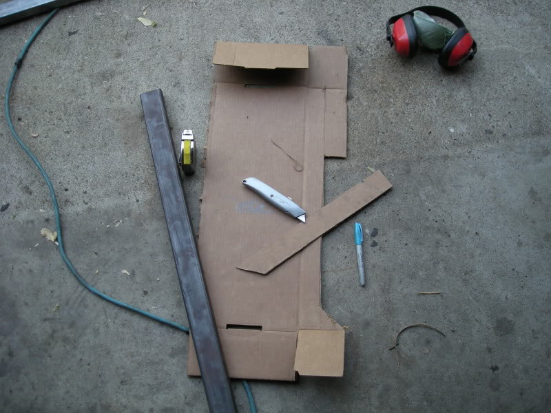
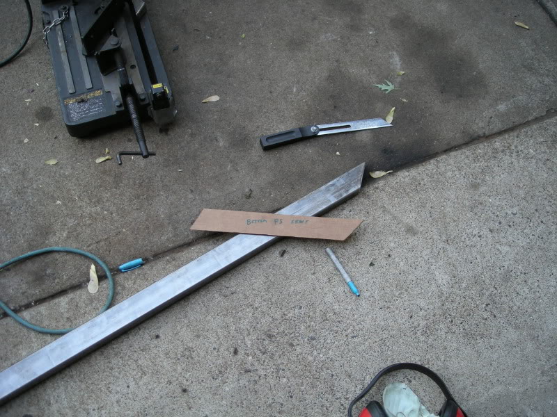
I got started on the center tubes last week. i pretty much wrap them up tonight.
Cardboard worked great for mocking up the angles.
Cardboard worked great for mocking up the angles.
06-09-2009, 10:55 PM
#95
Supreme Member
Thread Starter
iTrader: (18)
Join Date: Dec 2007
Location: Minnesota
Posts: 1,924
Likes: 0
Received 12 Likes
on
9 Posts
Car: 84 camaro, 88 trans am, 98 camaro
Engine: Modded , stock, LSX modded
Transmission: 700r4, 700r4, t-56
Axle/Gears: 327, 308, 373
Re: Sub frames (final design and build)
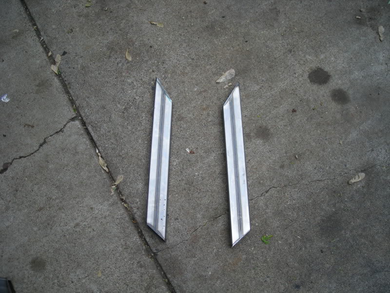
last set of tubes to be tacked on!
06-09-2009, 10:58 PM
#96
Supreme Member
Thread Starter
iTrader: (18)
Join Date: Dec 2007
Location: Minnesota
Posts: 1,924
Likes: 0
Received 12 Likes
on
9 Posts
Car: 84 camaro, 88 trans am, 98 camaro
Engine: Modded , stock, LSX modded
Transmission: 700r4, 700r4, t-56
Axle/Gears: 327, 308, 373
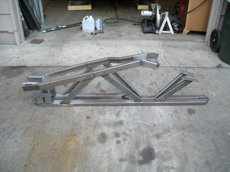
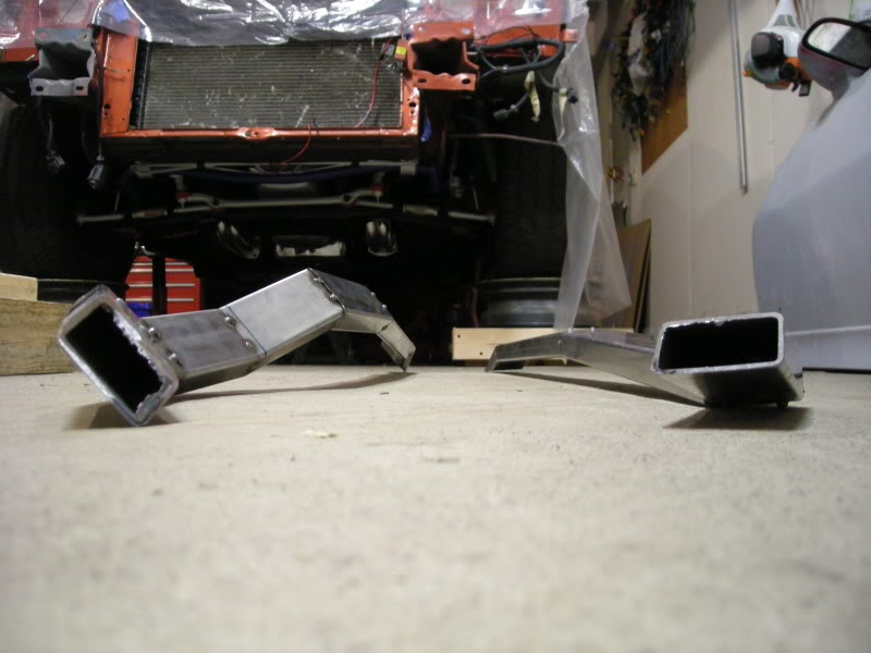
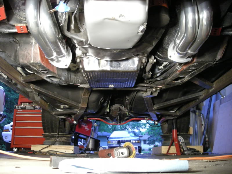
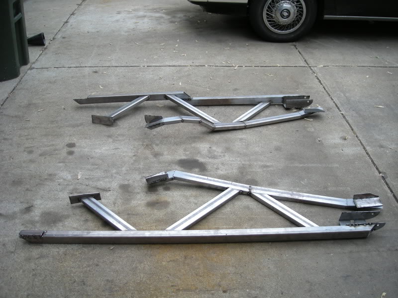
Re: Sub frames (final design and build)
Here they are! i will double check my work tomorrow before i cut the tacks off the factory frame rails and i will take some better pics of them off the car.
06-09-2009, 11:10 PM
#97
Supreme Member
Thread Starter
iTrader: (18)
Join Date: Dec 2007
Location: Minnesota
Posts: 1,924
Likes: 0
Received 12 Likes
on
9 Posts
Car: 84 camaro, 88 trans am, 98 camaro
Engine: Modded , stock, LSX modded
Transmission: 700r4, 700r4, t-56
Axle/Gears: 327, 308, 373
Re: Sub frames (final design and build)
 06-10-2009, 08:47 PM
#98
Supreme Member
Thread Starter
iTrader: (18)
Join Date: Dec 2007
Location: Minnesota
Posts: 1,924
Likes: 0
Received 12 Likes
on
9 Posts
Car: 84 camaro, 88 trans am, 98 camaro
Engine: Modded , stock, LSX modded
Transmission: 700r4, 700r4, t-56
Axle/Gears: 327, 308, 373
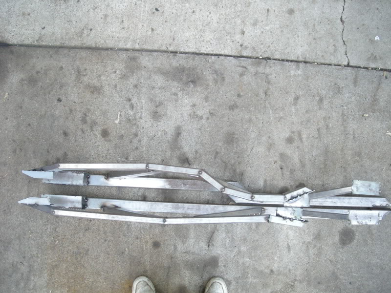
Re: Sub frames (final design and build)
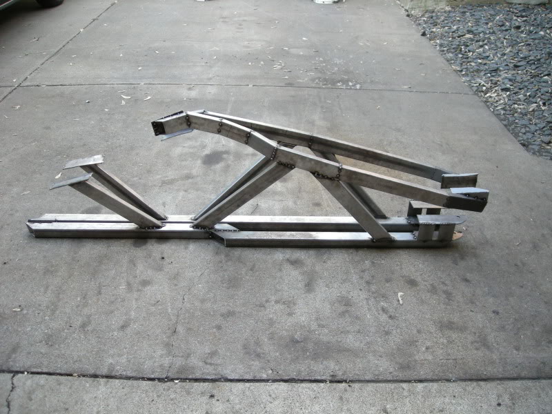
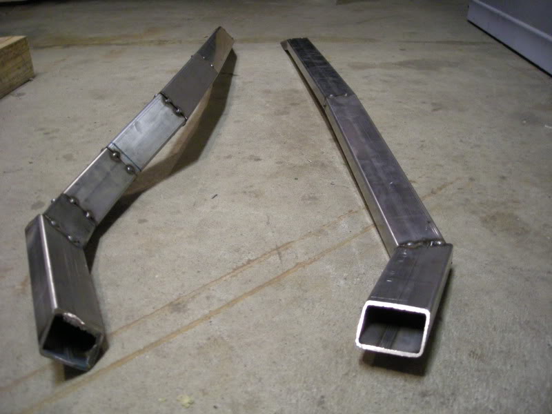
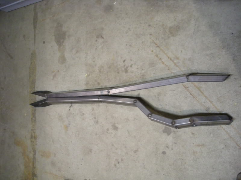
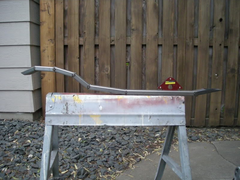
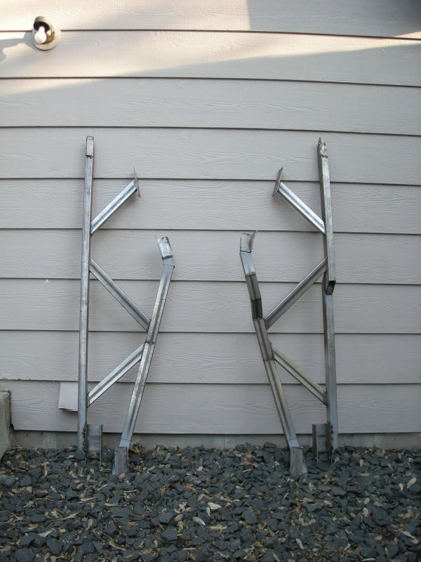
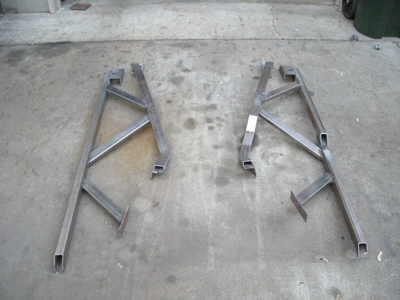
Here they are off the car.
Looking at them from the top.
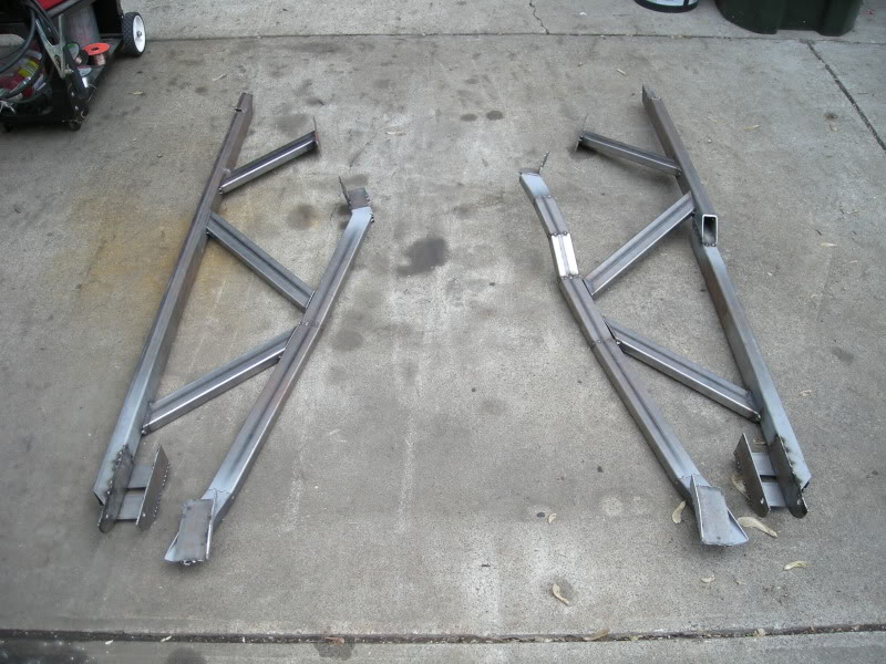
Looking at them from the top.
Last edited by FueledSoul; 06-10-2009 at 08:55 PM.
06-10-2009, 08:49 PM
#99
Supreme Member
Thread Starter
iTrader: (18)
Join Date: Dec 2007
Location: Minnesota
Posts: 1,924
Likes: 0
Received 12 Likes
on
9 Posts
Car: 84 camaro, 88 trans am, 98 camaro
Engine: Modded , stock, LSX modded
Transmission: 700r4, 700r4, t-56
Axle/Gears: 327, 308, 373
Re: Sub frames (final design and build)
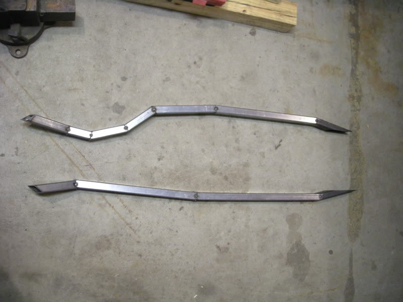
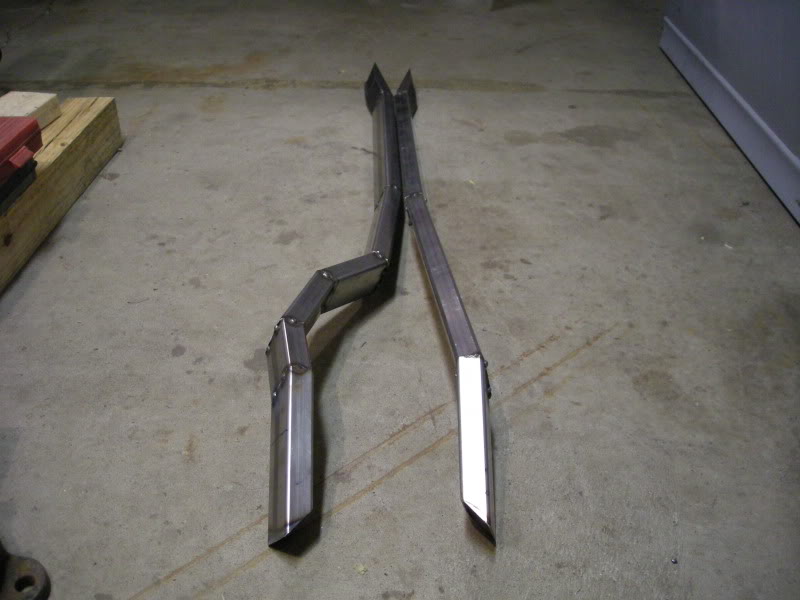
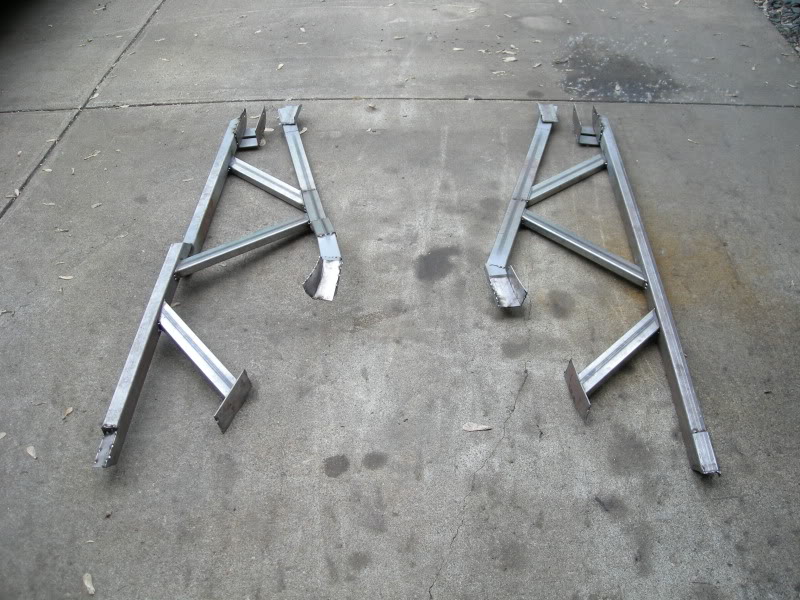
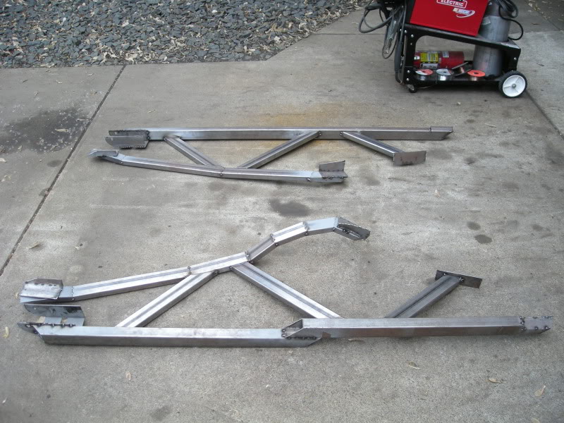
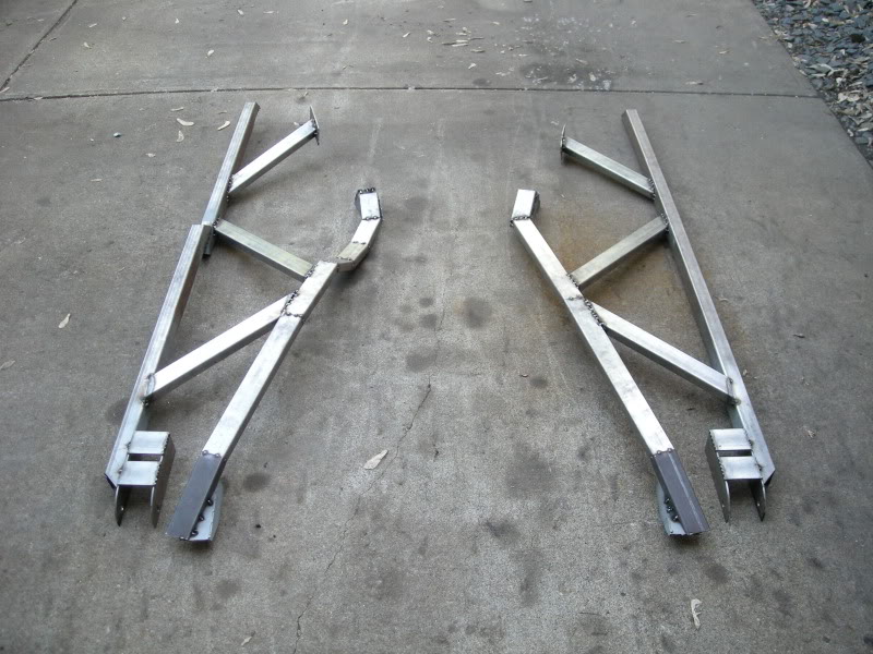
Looking at the from the bottem.
Last edited by FueledSoul; 06-10-2009 at 08:56 PM.
06-10-2009, 09:02 PM
#100
Supreme Member
Thread Starter
iTrader: (18)
Join Date: Dec 2007
Location: Minnesota
Posts: 1,924
Likes: 0
Received 12 Likes
on
9 Posts
Car: 84 camaro, 88 trans am, 98 camaro
Engine: Modded , stock, LSX modded
Transmission: 700r4, 700r4, t-56
Axle/Gears: 327, 308, 373
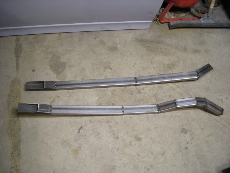
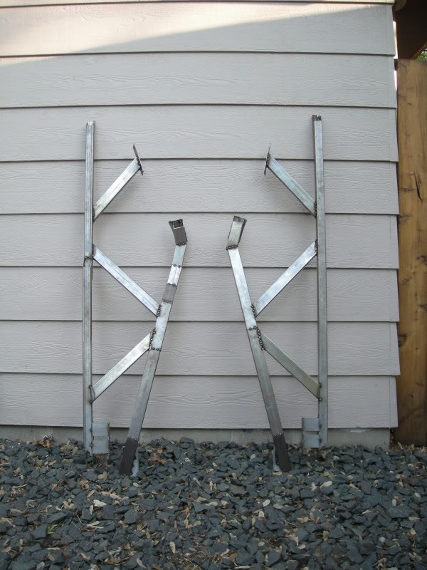
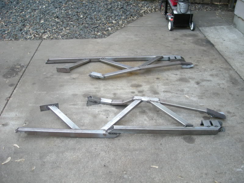
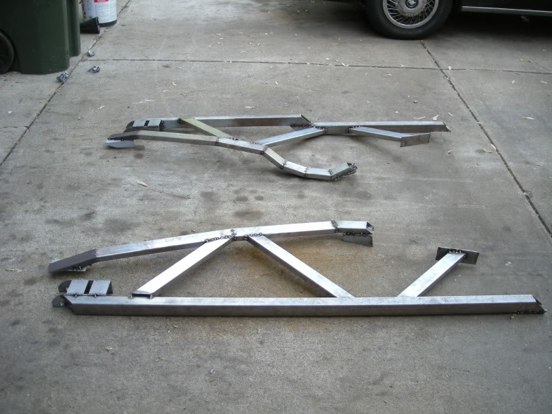
Re: Sub frames (final design and build)
Both sides weigh the same and are built close to identical as possible.