**Subframe Connector Plans**
 02-17-2010, 05:16 PM
#1
Member
Thread Starter
iTrader: (1)
Join Date: Feb 2009
Location: Hortonville, Wisconsin
Posts: 188
Likes: 0
Received 0 Likes
on
0 Posts
Car: 82 Firebird
Engine: Boosted LSX
Transmission: Built 4L60E
Axle/Gears: 4th Gen 3.42s
**Subframe Connector Plans**
So im building up a 383 stroker motor and putting it in my 82 firebird that has ttops. I am a 17 year old kid and dont have the greatest funds as the motor has drained my bank account. I know that i will be needing some sbc's but like i said, i dont have the cash to buy them. My dads good friends with a guy that can fabricate us up anything we think of but i want to get a good set of plans for bolt in connectors. Can any of you TGO members send me some plans or dimensions of your subframe connectors; like i said, id prefer bolt ins. Thanks alot.


 02-17-2010, 05:29 PM
#3
Member
Thread Starter
iTrader: (1)
Join Date: Feb 2009
Location: Hortonville, Wisconsin
Posts: 188
Likes: 0
Received 0 Likes
on
0 Posts
Car: 82 Firebird
Engine: Boosted LSX
Transmission: Built 4L60E
Axle/Gears: 4th Gen 3.42s
Re: **Subframe Connector Plans**
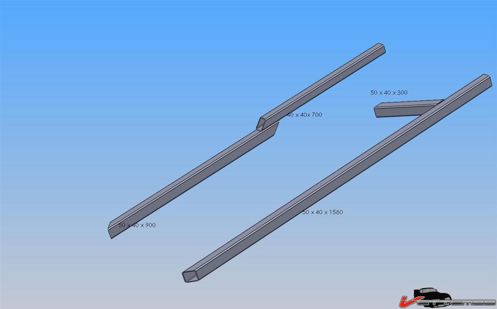
What are the angles cut on the ends of those if that matters? and what would i have to do to make this a bolt in setup?
Also, would you happen to have a picture of this setup on a car?
Also, would you happen to have a picture of this setup on a car?
02-17-2010, 05:31 PM
#4
Senior Member

Join Date: Jun 2008
Location: Norfolk VA
Posts: 1,298
Likes: 0
Received 2 Likes
on
2 Posts
Car: 85 Camaro IROC
Engine: 5.7 TPI
Transmission: 700-R4
Axle/Gears: open rear, 3.42 gears
Re: **Subframe Connector Plans**
the easiest way is to measure it yourself, that way there is no translation errors when we relay the dimensions...
you want to bring the SFC's from the big chunk where the Lower Control Arms (LCA's) mount up to the front of the car and connect it to the jacking pad.
basically, if you look at a diagram of where to jack the car up from, connect those two points with steel bar and you are set.
mine are made by UMI and look like this
http://www.umiperformance.com/catalo...roducts_id=127
click on the picture and scroll thru the pics they have listed.
this should give you a good idea of how to make yours and where to measure.
weld in connectors are FAR superior.
i wouldnt in a million years put bolt in connectors, even if they were free.
 02-17-2010, 09:01 PM
#6
Member

iTrader: (4)
Join Date: Apr 2008
Location: Tulsa Oklahoma
Posts: 482
Likes: 0
Received 2 Likes
on
2 Posts
Car: 1990 IROC-Z 1LE
Engine: 5.7 TPI
Transmission: 700R4
Axle/Gears: G92 3.23
Re: **Subframe Connector Plans**
Bolts are only to hold things in place while you gingerly drive to the welders shop. Make sure you put them on with the suspension loaded up (frame not lifted).
02-18-2010, 12:17 AM
#7
Supreme Member
iTrader: (1)
Join Date: Jul 1999
Posts: 3,257
Likes: 0
Received 5 Likes
on
3 Posts
Car: Turbo Buick
Engine: 3.8 V6
Re: **Subframe Connector Plans**
You don't need subframe connectors. The horsepower you generate is not going to twist your car or produce the cracks you see at the top corner of the roof. This is a common exaggeration/misunderstanding that has been perpetuated on thirdgen.org since the mid 90s when it wasn't even thirdgen.org.
If you think about the forces at work you'll quickly realize that cornering or hitting bumps, dips, etc in the road put far more stress in the areas that need strengthening than your engine ever will. Another way to confirm this is to grab a Gtech type device and compare raw g force data for all the axis.
There have been members of who lifted the front wheels at will with T tops and no SFCs. And an even more brutal test was when these cars were new they were road raced in SCCA showroom stock with no subframe connectors. Is it optimal? No. Is it doable? Obviously.
Trending Topics
02-18-2010, 03:20 AM
#8
Junior Member
Join Date: Sep 2008
Location: Olympia
Posts: 88
Likes: 0
Received 0 Likes
on
0 Posts
Car: '91-Z28/'03 Honda 919
Engine: L98
Transmission: 700R4
Axle/Gears: '99 Zexel 3.42
Re: **Subframe Connector Plans**
Even if the engine does not have enough power to have any ill effects on the chassis it is a worth while investment for the overall structural integrity and ride quality of the vehicle. My car developed the cracks on the roof with no hotrodding or highpowered engine. Your best bet is to get under the car and figure out your own design, and customize it for your own application.
02-18-2010, 01:19 PM
#9
Member
Thread Starter
iTrader: (1)
Join Date: Feb 2009
Location: Hortonville, Wisconsin
Posts: 188
Likes: 0
Received 0 Likes
on
0 Posts
Car: 82 Firebird
Engine: Boosted LSX
Transmission: Built 4L60E
Axle/Gears: 4th Gen 3.42s
Re: **Subframe Connector Plans**
I want the dimensions and whatnot off of the UMI kit that is pictured above, if anyone has any lemme know. I cant get under my car right now and i want these done by summer.
The following 2 users liked this post by KITT1983:
Chevy86 IROC-Z (02-09-2022), dennisbernal91z (05-15-2023)

The following 2 users liked this post by GTA1990:
91banditt2 (05-19-2023), KR81 (02-15-2022)
05-11-2023, 08:40 AM
#16
Member

Re: **Subframe Connector Plans**
Well, rather than start a new post......could 1.5 x 1.5 x 0.125 square tubing be used? I can get some very cheap.
05-11-2023, 08:09 PM
#17
Member

Re: **Subframe Connector Plans**
The set of inner sfc's I bought from heidts or UMI or something weren't really all that beefy looking. . . maybe 1.25x .120 round tube with some bends. I used 2x2x.120 square tube for my outer connectors, tied the into the factory subframe in a few spots, and stitched them to the rocker seam.
The following users liked this post:
lonesomeloser (05-11-2023)
05-13-2023, 04:20 AM
#18
Re: **Subframe Connector Plans**
These threads always throw me... where are people getting steel that is cheaper than buying something like the jegster SFC's? I mean by the time I buy the steel, cut it, weld it (and most of the people starting these threads will have to pay or bribe someone to fab/weld these things, they don't have the welder or the skills), weld materials, prep it and coat it with something (if you're not going to powder coat it then you're probably talking about an etching primer and some decent paint to keep them from getting nasty) I don't see how you could do it for much less than materials.
Must be a lot of steel falling off the backs of trucks and welders working for cheap beer.
BTW, I get the likes of Twin_turbo doing it, being in Europe, shipping and various taxes... but he also seems to have the ability to do his own work.
Must be a lot of steel falling off the backs of trucks and welders working for cheap beer.
BTW, I get the likes of Twin_turbo doing it, being in Europe, shipping and various taxes... but he also seems to have the ability to do his own work.
The following 2 users liked this post by 83 Crossfire TA:
91banditt2 (05-19-2023), dennisbernal91z (05-15-2023)
05-13-2023, 09:03 PM
#19
Member
Re: **Subframe Connector Plans**
These threads always throw me... where are people getting steel that is cheaper than buying something like the jegster SFC's? I mean by the time I buy the steel, cut it, weld it (and most of the people starting these threads will have to pay or bribe someone to fab/weld these things, they don't have the welder or the skills), weld materials, prep it and coat it with something (if you're not going to powder coat it then you're probably talking about an etching primer and some decent paint to keep them from getting nasty) I don't see how you could do it for much less than materials.
Must be a lot of steel falling off the backs of trucks and welders working for cheap beer.
BTW, I get the likes of Twin_turbo doing it, being in Europe, shipping and various taxes... but he also seems to have the ability to do his own work.
Must be a lot of steel falling off the backs of trucks and welders working for cheap beer.
BTW, I get the likes of Twin_turbo doing it, being in Europe, shipping and various taxes... but he also seems to have the ability to do his own work.
05-20-2023, 02:53 PM
#20
Re: **Subframe Connector Plans**
You certainly could. Rigidity is key. Add braces wherever it looks weak. May not be as rigid as 2x2x.188 wall, but you could always weld 2 pieces together, essentially giving yourself a 1.5x3" tube. . .
The set of inner sfc's I bought from heidts or UMI or something weren't really all that beefy looking. . . maybe 1.25x .120 round tube with some bends. I used 2x2x.120 square tube for my outer connectors, tied the into the factory subframe in a few spots, and stitched them to the rocker seam.
The set of inner sfc's I bought from heidts or UMI or something weren't really all that beefy looking. . . maybe 1.25x .120 round tube with some bends. I used 2x2x.120 square tube for my outer connectors, tied the into the factory subframe in a few spots, and stitched them to the rocker seam.
05-20-2023, 05:00 PM
#21
Re: **Subframe Connector Plans**
I can weld and paint also... the jegsters are one of the best deals around (cost and performance) and they weld in nicely, and for those that can't weld and want to save a few $, bolt them in and drive it to a shop to weld them in, you'll save the money for the grunt work of just getting them in position.
05-20-2023, 05:48 PM
#22
Member
Re: **Subframe Connector Plans**
Welders are cheap. Flux core 110 welders are $100 and gas welders aren't much more. Welding the factory 14 gauge steel on the torque boxes/subframe to some 1/8 sheet and tubing is an easy and cheap way to brace up your car. That's more than thick enough for subframe connectors if a good design is used, and for a cheap 110 welder you will get good results with basically no skill.
Something is always better than nothing, and this isn't rocket science. Crawl under the car with some cardboard and scratch paper and figure out a design. It's easy to find cheap used steel. Scrap yards often sell stuff. Check the local steel yards rather than going online, prices are usually better. Sheetmetal shops/ fab shops often sell drops and cutoffs for cheap. Check craigslist. . .
Something is always better than nothing, and this isn't rocket science. Crawl under the car with some cardboard and scratch paper and figure out a design. It's easy to find cheap used steel. Scrap yards often sell stuff. Check the local steel yards rather than going online, prices are usually better. Sheetmetal shops/ fab shops often sell drops and cutoffs for cheap. Check craigslist. . .

Thread
Thread Starter
Forum
Replies
Last Post
TMZIrocZ350
Engine/Drivetrain/Suspension Parts for Sale
1
10-07-2015 12:09 PM
tmork454
Transmissions and Drivetrain
0
09-29-2015 06:33 PM
1982, 1983, 2000, 85, body, buick, camaro, connector, connectorplans, connectors, diagram, fbody, plans, subframe, subframeconnector