
Sub frames (design rough draft)

Thread Starter

Joined: Dec 2007
Posts: 1,924
Likes: 12
From: Minnesota
Car: 84 camaro, 88 trans am, 98 camaro
Engine: Modded , stock, LSX modded
Transmission: 700r4, 700r4, t-56
Axle/Gears: 327, 308, 373
Sub frames (design rough draft)
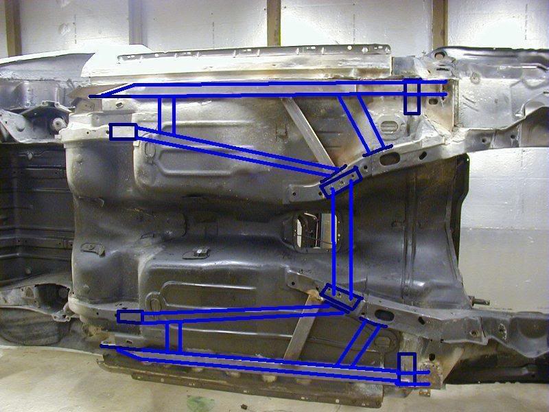
I will be making my own. i don't know what gauge of steel to use, most sub frames iv seen are (30 gauge 0.120" wall) i find that to become some what heavy especially with the way i want to run mine. So im wounding what the tossup is for strength Vs weight and what would be a strong but adaquit for what i want with out being to heavy i plan on going with rectangular steel tubing and around something like 2.250� x 1.250� the size of the tubing is also going to add or take off some weight to. So just looking for some ideas with all the above. this is just in the rough till i decide on what i want but in the mean time id like some insight on anything related.


Joined: Oct 2004
Posts: 805
Likes: 3
From: Charleston, SC
Car: '85 TA
Engine: 350 turbo
Transmission: T56
Axle/Gears: 3.70 posi 9bolt
Re: Sub frames (design rough draft)
What are your plans for the exhaust? I just finished my own with 1-1/2" sq. tubing x 1/8" wall and it was a joint effort between installing the subframe connectors on the passenger side and the 3" exhaust. Also .120" is 11ga, which I think is a good compromise between weight and strength for the sub frame. On your design, the outer long pieces are fine, since that's been done before, but it looks like the inner pieces would be a pain to weld due to the uneven floor panel of the back seats.
Moderator


Joined: Jul 1999
Posts: 17,273
Likes: 171
From: 51�N 114�W, 3500'
Car: 87 IROC L98
Engine: 588 Alcohol BBC
Transmission: Powerglide
Axle/Gears: Ford 9"/31 spline spool/4.86
Re: Sub frames (design rough draft)
A little excessive. This is all I have for mine. My front attachment point is going to the subframe. All your other attachment points do not go to the subframe.


Junior Member
Joined: Feb 2009
Posts: 33
Likes: 0
Car: 99 B4C, 89 RS
Engine: LS1, 2.8
Transmission: 4L60E, T5
Axle/Gears: 3.23, 3.42
Re: Sub frames (design rough draft)
Looks good, I also plan to make my own SFC, I think I will be using 2x3 rectangular 11ga. tubing for the main outer rails if they will fit. I will use the biggest rectangular tubing that I can tuck up behind the rockers.
If weight is an issue, why not delete the inner rails and make the outers alittle bigger? The rear floor pan is the problem with the inner connectors,it drops so low.
If weight is an issue, why not delete the inner rails and make the outers alittle bigger? The rear floor pan is the problem with the inner connectors,it drops so low.
Junior Member
Joined: Feb 2009
Posts: 33
Likes: 0
Car: 99 B4C, 89 RS
Engine: LS1, 2.8
Transmission: 4L60E, T5
Axle/Gears: 3.23, 3.42
Re: Sub frames (design rough draft)
Stephan,did you cut the floor or run the rails under it? Maybe I will cut the floor of mine and connect the frames together, seems the rear passenger floor would be the only thing with a rail going through it.
Moderator
Joined: Jul 1999
Posts: 17,273
Likes: 171
From: 51�N 114�W, 3500'
Car: 87 IROC L98
Engine: 588 Alcohol BBC
Transmission: Powerglide
Axle/Gears: Ford 9"/31 spline spool/4.86
Re: Sub frames (design rough draft)
Mine run right under the floor. The driver side one runs directly under the seat. I welded pieces of angle iron off the sides to provide a place to bolt the seat to the "frame".
At the rear there's quite a bit of fabrication. The ends were notched to angle down. A simple triangle cut to cover the end would work just as good. Because the SFC sits on/under the rear subframe, strips of flat steel were then welded to the sides of the SFC and to the side of those rear sub frames.
The front is a simple diagonal cut and weld to the subframe. Mine might be slightly forward from where I've drawn them to make the SFC straighter.
When I first put them in many years ago, the car still had a single 3" exhaust running roughly where the stock exhaust goes. To clear the exhaust pipe, the passenger side SFC has a c-section cut into it.
One advantage I've had to this style SFC is it allowed me to fabricate different types of tranny mount crossmembers over the years. I simply attached the crossmember to the SFC instead of the terribly designed factory mount points. It was wider but allowed a simple way of easily install and remove the crossmember without having to worry about stripping the mount threads.
As I mentioned above. My front and rear mount points are to the sub frames. All those other mounting points are sheet metal. The goal is to eliminate that huge section of sheet metal between the front and rear with a section of frame to keep the subframes from flexing the body. That one simple strip on both sides completes the frame. If you want to make it stronger, find a way to X the frame between the SFC.
Trending Topics
Thread Starter
Joined: Dec 2007
Posts: 1,924
Likes: 12
From: Minnesota
Car: 84 camaro, 88 trans am, 98 camaro
Engine: Modded , stock, LSX modded
Transmission: 700r4, 700r4, t-56
Axle/Gears: 327, 308, 373
Re: Sub frames (design rough draft)
What are your plans for the exhaust? I just finished my own with 1-1/2" sq. tubing x 1/8" wall and it was a joint effort between installing the subframe connectors on the passenger side and the 3" exhaust. Also .120" is 11ga, which I think is a good compromise between weight and strength for the sub frame. On your design, the outer long pieces are fine, since that's been done before, but it looks like the inner pieces would be a pain to weld due to the uneven floor panel of the back seats.
both umi, and spohn use some heavy gauge stuff . http://www.umiperformance.com/2400?category_id=113
http://www.spohn.net/shop/1982-1992-...-Top-Cars.html
i realize the floor pan issue. thats another thing im going to have to consider - Not the way the floor pans are shape but rather the clearance issues, i plan to run them as close to the floor pans as possible
Thread Starter
Joined: Dec 2007
Posts: 1,924
Likes: 12
From: Minnesota
Car: 84 camaro, 88 trans am, 98 camaro
Engine: Modded , stock, LSX modded
Transmission: 700r4, 700r4, t-56
Axle/Gears: 327, 308, 373
Re: Sub frames (design rough draft)
it might be a good idea to leave it back where the transmission crossmember bolts to.

Last edited by FueledSoul; Mar 3, 2009 at 09:41 PM.
Banned
iTrader: (12)
Joined: Jul 1999
Posts: 12,212
Likes: 13
From: Bertram (outside Austin), TX
Car: 87 GTA
Engine: L98
Transmission: 700R4
Axle/Gears: Dana M78 3.27 posi
Re: Sub frames (design rough draft)
Kinda reminds me of the Kenny Brown Double Diamond 4th gen design.

Thread Starter
Joined: Dec 2007
Posts: 1,924
Likes: 12
From: Minnesota
Car: 84 camaro, 88 trans am, 98 camaro
Engine: Modded , stock, LSX modded
Transmission: 700r4, 700r4, t-56
Axle/Gears: 327, 308, 373
Re: Sub frames (design rough draft)
iv seen them before theres some other company's that have that design as well
Last edited by FueledSoul; Mar 3, 2009 at 09:29 PM.
Thread Starter
Joined: Dec 2007
Posts: 1,924
Likes: 12
From: Minnesota
Car: 84 camaro, 88 trans am, 98 camaro
Engine: Modded , stock, LSX modded
Transmission: 700r4, 700r4, t-56
Axle/Gears: 327, 308, 373
Re: Sub frames (design rough draft)
thought about adding a rear bar that fallows the contours of the drive shaft tunnel and connects both rearward sub frames 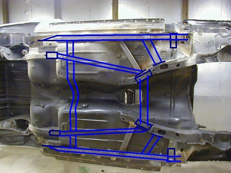
only thing is im not sure what i have for room with my lager diameter drive shaft or after market torque arm.
only thing is im not sure what i have for room with my lager diameter drive shaft or after market torque arm.
Junior Member
Joined: Feb 2009
Posts: 33
Likes: 0
Car: 99 B4C, 89 RS
Engine: LS1, 2.8
Transmission: 4L60E, T5
Axle/Gears: 3.23, 3.42
Re: Sub frames (design rough draft)
I think 11ga. would be good for the connectors if built right, the factory subframes are thinner than that I'm sure. If you want to use 1"x1" square tubing then yes use a thicker wall like .125 or .188.
I like the original connectors in this picture, connecting the cowl and front subframe to the rear.
Banned
iTrader: (12)
Joined: Jul 1999
Posts: 12,212
Likes: 13
From: Bertram (outside Austin), TX
Car: 87 GTA
Engine: L98
Transmission: 700R4
Axle/Gears: Dana M78 3.27 posi
Re: Sub frames (design rough draft)
Looks like overkill IMO. Why have two pairs of rails connecting the front and rear? I'm no engineer, but I think if the rails were out the farthest(close to the rockers) they would do a better job, then connect them together with a crossmember, with a driveshaft loop in the tunnel.
Some are made to run inwards, some outwards. Combine them both & you'll see a difference, even on hardtop cars.
Supreme Member
iTrader: (5)
Joined: Aug 2006
Posts: 2,491
Likes: 6
From: Cleveland, Ohio
Car: 89' IROC-Z
Engine: LO3
Transmission: 700R4
Axle/Gears: 10-Bolt/2.73
Re: Sub frames (design rough draft)
This looks like the ultimate in under carriage bracing. I always see those honda civics and 240sx's with full undercarriage bracing, but never seen that for our cars (which actually have the uni-body) and need it...well maybe not need but would like.
This looks like something to test when everything is on the car already.
I like the whole design, may look into it when I get far enough to need it. Right now Im on the motor. Next is brakes, tires and shocks and springs. Then ITS ON!
Keep us updated. I'd like to see how these come out.
This looks like something to test when everything is on the car already.
I like the whole design, may look into it when I get far enough to need it. Right now Im on the motor. Next is brakes, tires and shocks and springs. Then ITS ON!
Keep us updated. I'd like to see how these come out.
Joined: Jun 2000
Posts: 5,364
Likes: 51
From: Enschede, Netherlands
Car: 82 TA 87 IZ L98 88 IZ LB9 88 IZ L98
Engine: 5.7TBI 5,7TPI 5.0TPI, 5,7TPI
Transmission: T5, 700R4, T5, 700R4
Axle/Gears: 3.08, 3.27, 3.45, 3.27
Re: Sub frames (design rough draft)
Since there are already 2 bars running diagonally to the subframe, I would triangulate the additional ones you drew in there from where the otehrs attach to the subframe and then back out to the outside rail,that will give you a nice triangle on both sides that ties into existing points.
Guest
Posts: n/a
Re: Sub frames (design rough draft)
The R-L across the trans tunnel bar as posted above is not going to do a whole lot. For the level of difficulty it would take to get that to work, may as well just leave it out. The primary areas you need to address are the F-R bending and torsion around an imaginary centerline of the car F-R. The easiest way to work against the torsion forces is by making the frame rails as stiff as possible. One way is multiple rails. Ideally, it would be nice to tie the right and left together, but you'd want to do that in an X pattern not a box pattern. If you just draw an X from the end connection points of the two rails nearest the sides of the car, thats ideal. You'll notice it makes triangles, something you can see on just about any multiple element bridge in this country or under the roofs of a whole bunch of houses. The first drawing you put up is closest to that, that is the direction you should go.
Joined: Jun 2000
Posts: 5,364
Likes: 51
From: Enschede, Netherlands
Car: 82 TA 87 IZ L98 88 IZ LB9 88 IZ L98
Engine: 5.7TBI 5,7TPI 5.0TPI, 5,7TPI
Transmission: T5, 700R4, T5, 700R4
Axle/Gears: 3.08, 3.27, 3.45, 3.27
Re: Sub frames (design rough draft)
This is what I mean:

Thread Starter
Joined: Dec 2007
Posts: 1,924
Likes: 12
From: Minnesota
Car: 84 camaro, 88 trans am, 98 camaro
Engine: Modded , stock, LSX modded
Transmission: 700r4, 700r4, t-56
Axle/Gears: 327, 308, 373
Re: Sub frames (design rough draft)


Thread Starter
Joined: Dec 2007
Posts: 1,924
Likes: 12
From: Minnesota
Car: 84 camaro, 88 trans am, 98 camaro
Engine: Modded , stock, LSX modded
Transmission: 700r4, 700r4, t-56
Axle/Gears: 327, 308, 373
Re: Sub frames (design rough draft)
As far as x-ing goes it would take a lot of work to completely do that. 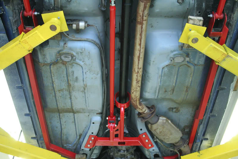
this would be more simple but i don't think it would be very torsionally strong
this would be more simple but i don't think it would be very torsionally strong
Supreme Member
iTrader: (5)
Joined: Aug 2007
Posts: 1,525
Likes: 1
From: Milwaukee, Wisconsin
Car: 1987 IROC-Z
Engine: 383 with Edelbrock ProFlow EFI
Transmission: TH350
Axle/Gears: 12 bolt 3.73 Eaton posi
Re: Sub frames (design rough draft)
Nothing is over kill when it comes to building a ridged, strong chassis. If you think my design is over kill, then you shouldn't even look at real track cars. The level of engineer going into them is nil compared to what I'm doing. These guys sit at drafting tables for weeks on end, I'm just using MS Paint.
About the subframes... there is a fine line between bracing the car and adding extra weight. I think you're pushing it with the second rear cross brace. Based on the picture of the UMI SFC, I think it would be a really tight fit (if it would fit at all) if you decide to use the rear cross brace.
Junior Member
Joined: Feb 2009
Posts: 33
Likes: 0
Car: 99 B4C, 89 RS
Engine: LS1, 2.8
Transmission: 4L60E, T5
Axle/Gears: 3.23, 3.42
Re: Sub frames (design rough draft)
I think a set of u-shaped channel that contours to the floor like the factory subframes. A stamped steel rail that is parallel to the ground but height changes with the floor and can be welded front to back to the floor and subframes. Just an idea to use the floor as the top of the tube.
Thread Starter
Joined: Dec 2007
Posts: 1,924
Likes: 12
From: Minnesota
Car: 84 camaro, 88 trans am, 98 camaro
Engine: Modded , stock, LSX modded
Transmission: 700r4, 700r4, t-56
Axle/Gears: 327, 308, 373

Supreme Member
iTrader: (1)
Joined: Sep 2008
Posts: 1,347
Likes: 2
From: Western WA
Car: 85 Camaro
Engine: No
Transmission: No
Axle/Gears: No
Re: Sub frames (design rough draft)
Nothing over kill when it comes to building a ridge, strong chassis. if you think my design is over kill then you shouldn't even look at real track cars the level of engineer going into them is nil compared to what im doing these guys sit at drift tables for weeks on end im just using ms paint.
Your drawing does look really excessive.
I just put on sfc's, they fit up between the LCA mount and the subframe, and I cut out the floorpan where it was needed, then welded to the floorpan, front subframe, rear subframe, and rear LCA mounts, and welded in gussets. That seems like the best way to do it for strength vs weight.
I believe that instead of using so much under-floor bracing, it would be much stronger to put a cage in.
I didn't lose any ground clearance, and they are low enough that the carpet doesn't need to be trimmed.
Thread Starter
Joined: Dec 2007
Posts: 1,924
Likes: 12
From: Minnesota
Car: 84 camaro, 88 trans am, 98 camaro
Engine: Modded , stock, LSX modded
Transmission: 700r4, 700r4, t-56
Axle/Gears: 327, 308, 373
Re: Sub frames (design rough draft)
What do you plan on using your car for that you think it needs to be so reinforced? Will it be a 'real track car'?
Your drawing does look really excessive.
I just put on sfc's, they fit up between the LCA mount and the subframe, and I cut out the floorpan where it was needed, then welded to the floorpan, front subframe, rear subframe, and rear LCA mounts, and welded in gussets. That seems like the best way to do it for strength vs weight.
I believe that instead of using so much under-floor bracing, it would be much stronger to put a cage in.
I didn't lose any ground clearance, and they are low enough that the carpet doesn't need to be trimmed.
Thread Starter
Joined: Dec 2007
Posts: 1,924
Likes: 12
From: Minnesota
Car: 84 camaro, 88 trans am, 98 camaro
Engine: Modded , stock, LSX modded
Transmission: 700r4, 700r4, t-56
Axle/Gears: 327, 308, 373
Re: Sub frames (design rough draft)
Heres some good examples.


Think if you just added more bracing on the sides of the doors instead of trying to triangulate it.
Think if you just added more bracing on the sides of the doors instead of trying to triangulate it.


Joined: Feb 2007
Posts: 4,770
Likes: 64
From: Trumbull CT
Car: 87 TA clone
Engine: 70/70 Turbo 5.3 LS
Transmission: bullet proof 2004R
Axle/Gears: ford 8.8, 3.55 gears
Re: Sub frames (design rough draft)
altho your drawings look strong ur doing to much. your basically adding extra weight. if you want to add all that metal u dont want to be using thick steel. the point of the thick steel is to use less material and achieve max rigidy. altho i like your designs and it would really reinforce the unibody. all that tubing is gona add weight. if your gona use more tubing and more mounting points u could use .095 wall tubing or square tubing. mine are 2x2x.095 square tubing. that car stock has rigidy but u just want to reinforce it. your basiaclly framing the car. no real need for this. a simple subframe with suffice. weak parts after a simple subframe install will be the stock stubframes and the spot welds of the car.
i would use thinner material like .095" and simplifying it, incorporating the subframes into the floor pan/subframes like thru floor will further increase the subframes rigidy allowing for less material to be used as well as thinner material. u want to add rigidy but save on weight. all that material would weight as much as a 6-8pt roll cage but to each his own. if u want to do it then go for it. ppl do run 2 diff types of subframes for extra rigidy. but depending on what the car is being used for it might not be necessary. if the car will be used on the track and the power u would be using for a car that needs 2 sets of subframes or your design would mean that u would prob be putting down enough power to have to run a cage. so now u have added even more weight when its not needed and prob not increased rigidy.
one well planned set of subframes and then a roll bar/cage would be more than sufficent. roll bars/cages are actually stronger than subframes due to the leverage they provide. which u cant get with subframes.
mine is basically like stephens, but i cut into the stock subframe, cut the floor and welded it into the floor and front subframe at the thickest point. the outer perimeter of the car isnt the strongest part. the rear LCA mount isnt actually the rear subframe. stephens red drawing attaches the actually subframes together.
Thread Starter
Joined: Dec 2007
Posts: 1,924
Likes: 12
From: Minnesota
Car: 84 camaro, 88 trans am, 98 camaro
Engine: Modded , stock, LSX modded
Transmission: 700r4, 700r4, t-56
Axle/Gears: 327, 308, 373
Re: Sub frames (design rough draft)
Great reply.
Joined: Feb 2007
Posts: 4,770
Likes: 64
From: Trumbull CT
Car: 87 TA clone
Engine: 70/70 Turbo 5.3 LS
Transmission: bullet proof 2004R
Axle/Gears: ford 8.8, 3.55 gears
Re: Sub frames (design rough draft)
sarcasm? lol if not glad to help. i think youd be better off not running a perimeter type subframe but a subframe like stephens. attach the actual rear/front srubframes together. and then add a 8pt cage. when i did mine it was a nite and day diffrence. and i have yet to get my new motor and rear to complete mine after my roll bar install. should make a huge diff. the cage will add more rigidy and leverage over a second set of subframes. but if u dont want the hassel of a cage on a street car that wont see track use and ur not gona make enough power to need a cage at the track then do your subframe setup.
alot of ppl dont kno this but our cars use the doors as part of the structual rigidy of the cars frame. ever wonder why the stock doors on a 3rd gen are so heavy? they are reinforced with heavy thick steel. this inside structure can be removed to shed a good bit of weight. since u dont really need the extra rigidy with the install of subframes and or cage/roll bar. food for thought if u want to counter act the increased wieght of dual subframe/roll bar once installed.
alot of ppl dont kno this but our cars use the doors as part of the structual rigidy of the cars frame. ever wonder why the stock doors on a 3rd gen are so heavy? they are reinforced with heavy thick steel. this inside structure can be removed to shed a good bit of weight. since u dont really need the extra rigidy with the install of subframes and or cage/roll bar. food for thought if u want to counter act the increased wieght of dual subframe/roll bar once installed.
Thread Starter
Joined: Dec 2007
Posts: 1,924
Likes: 12
From: Minnesota
Car: 84 camaro, 88 trans am, 98 camaro
Engine: Modded , stock, LSX modded
Transmission: 700r4, 700r4, t-56
Axle/Gears: 327, 308, 373
Re: Sub frames (design rough draft)
no that was a great post!
Thread Starter
Joined: Dec 2007
Posts: 1,924
Likes: 12
From: Minnesota
Car: 84 camaro, 88 trans am, 98 camaro
Engine: Modded , stock, LSX modded
Transmission: 700r4, 700r4, t-56
Axle/Gears: 327, 308, 373
Re: Sub frames (design rough draft)
hinges to striker - im aware of the whole door acting in that manner. 60" of open space and 101" wheel base nothing like it! lol
Senior Member
Joined: Jul 2008
Posts: 808
Likes: 2
From: Ft Wayne, IN
Car: 2003 F-150
Engine: 4.6L Modular V8
Transmission: 4R70W
Axle/Gears: Ford 8.8"/3.55 LSD
Re: Sub frames (design rough draft)
That combination would make for a really stiff subframe. The only thing that you would have to worry about is the things that you mentioned like exhaust routing, driveshaft clearance, and crossmember clearance. I'm not an engineer, but I think you could do this type of SFC if you used 1.5"x.049" square tube or 1.25"x.083" square tube, possibly even 1"x.083" square tube.
Also, how much structural strength can be gained by welding all the sheet metal together instead of the stock spot welds?
Finally, I've got a question about the Alston SFC. Why are they like that: https://www.secureway1.com/alston/in...?productID=183
Could we possibly take your guys design and continue on back with a fully triangulated design with 1"x.065" square tube or 1"x.049" square tube?
Joined: Feb 2007
Posts: 4,770
Likes: 64
From: Trumbull CT
Car: 87 TA clone
Engine: 70/70 Turbo 5.3 LS
Transmission: bullet proof 2004R
Axle/Gears: ford 8.8, 3.55 gears
Re: Sub frames (design rough draft)
first off the steel u stated was wayyy to thin. u would have to use steel that was at least as thick as the stock subframe. u dont brace/reinforce something that with a thinner metal than is already there. the thinnest material i would use would be .095" thats pretty thin its between a 12-14gauge steel. and the larger tubing would be stronger like 2"x2" not 1". most aftermarket frames use 2"x3" steel that is at least 1/8" or .125" thick. larger tubing deflects less, smaller tubing twists easier and doesnt spread the forces out more.
the only subframes ive seen with 1" square tubing is the chris alstons. posted in stephens pic. this tubing is thick like .133" and is triangulated and uses 1/4" plate. to tie them together. this is a totally diff design.
the stock spot welds allow flexing since there is large gaps between welds. stitch welding the stock subframes etc will increase its strength etc since the subframes will be attached to the steel in more places. allowing less flex.
Senior Member
Joined: Jul 2008
Posts: 808
Likes: 2
From: Ft Wayne, IN
Car: 2003 F-150
Engine: 4.6L Modular V8
Transmission: 4R70W
Axle/Gears: Ford 8.8"/3.55 LSD
Re: Sub frames (design rough draft)
first off the steel u stated was wayyy to thin. u would have to use steel that was at least as thick as the stock subframe. u dont brace/reinforce something that with a thinner metal than is already there. the thinnest material i would use would be .095" thats pretty thin its between a 12-14gauge steel. and the larger tubing would be stronger like 2"x2" not 1". most aftermarket frames use 2"x3" steel that is at least 1/8" or .125" thick. larger tubing deflects less, smaller tubing twists easier and doesnt spread the forces out more.
the only subframes ive seen with 1" square tubing is the chris alstons. posted in stephens pic. this tubing is thick like .133" and is triangulated and uses 1/4" plate. to tie them together. this is a totally diff design.
the stock spot welds allow flexing since there is large gaps between welds. stitch welding the stock subframes etc will increase its strength etc since the subframes will be attached to the steel in more places. allowing less flex.
the only subframes ive seen with 1" square tubing is the chris alstons. posted in stephens pic. this tubing is thick like .133" and is triangulated and uses 1/4" plate. to tie them together. this is a totally diff design.
the stock spot welds allow flexing since there is large gaps between welds. stitch welding the stock subframes etc will increase its strength etc since the subframes will be attached to the steel in more places. allowing less flex.
Thread Starter
Joined: Dec 2007
Posts: 1,924
Likes: 12
From: Minnesota
Car: 84 camaro, 88 trans am, 98 camaro
Engine: Modded , stock, LSX modded
Transmission: 700r4, 700r4, t-56
Axle/Gears: 327, 308, 373
Re: Sub frames (design rough draft)
Would you want to saddle the existing sub frames. or would a plate be fine? only thing i could see that would need something like that is where the LCA mount and wouldn't hurt to add more metal to that area

Member
iTrader: (12)
Joined: Sep 2006
Posts: 215
Likes: 0
From: Allentown, PA
Car: 87 Trans am
Engine: 350tpi
Transmission: 6spd
Axle/Gears: 4.10
Re: Sub frames (design rough draft)
I have 2 questions if the perimiter style is worse than the ones that go from front to rear subframe. Why are they the most comon ones sold, is it for ground clearence issues? And my second question is dosent top down solutiond sell a set of subframe conectors that do exactly that conect the front and rear subframes together and are made so they stay close to the floor pan. So wouldn't it be easyer to just buy them and weld them up. Yes I know you could probably make them cheaper but trying to keep ground clearence at a max might just be to much of a hassle.
Joined: Feb 2007
Posts: 4,770
Likes: 64
From: Trumbull CT
Car: 87 TA clone
Engine: 70/70 Turbo 5.3 LS
Transmission: bullet proof 2004R
Axle/Gears: ford 8.8, 3.55 gears
Re: Sub frames (design rough draft)
i didnt kno u were talking about chrome moly 89rs. if so u could get away with thinner but welding moly is a pain in the *** and is usually too expensive for most ppl. mild steel would be an easier choice even tho there is added weight.
fueledsoul... the saddle is not a bad design and i would def use it for the rear LCA mount subframe styles. the stock stuff is somewhat thin. but if would be better for a bolt in style subframe since u need to reinforce the bolt in area on both sides but this is notneccessary for weld in styles. u would have to weld all that around and thats not needed, alot of unneccessary work. the plate design will allow for more strength and spread the forces over a increased surface area.... the way i did mine was a 90 degree plate section. this is how i would tell u to do it. just make a 90degree bend in the plate and weld it to the subframe. like half the size of the saddle.this will help in stopping the twisting forces as well as adding rigidy to the stock subframe.
87tpi350... basically they design the perimieters for ease of installation. and theyre are already easy mounting points to the rear LCA. this is easier since no holes have to be drilled. they DO increase subframe strength but dont "actually" connect the front and rear subframes together. they attach the rear LCA and front subframe?wheel well supports below the driver/passengers feet. essentally the rear LCA mount is one stamped peice of steel that incorportates the rear subframe which is where the LCA mount gets its strength... but its not actually the rear subframe. the perimieter subframes also allow mostly the use of stock type exhaust systems. which is a plus since its less hastle for the installer which means they will sell more product. also if u notice on our cars there is absolutely nothing running on the outside perimieter of our cars on the undercarage. so why not put something there and since that section is acutally tucked up higher than the rest of the floor pan it allows for the subframe to be tucked up nicer.
the TDS is the only other type of aftermarket subframe that actually attaches the subframes differently than the BMR, UMI, SPOHN sfc. and is the only choice for ppl who want to run 2 types of SFC. since they dont interfere with eachother. also the only prob i see with the TDS is that it attaches at the very end of the front subframe... its basiacly the thinnest part of the front subframe. looks to be like a 20 gauge steel. farther up before the trans crossmemeber on the front subframe the steel is substantially stronger and is overlapped with 2 peices. this was a stronger part to mount to.
as far as too much of a hassle... depend son the fab skills of the individual. most follow the aftermarket designs and can make them for 1/4 the price and achieve the same if not better results if they modify the design. its really up the person and if its worth alil extra time. max clearance and strength would be with a thru floor design which requires more skill and time but u cant beat the results.
Senior Member
Joined: Jul 2008
Posts: 808
Likes: 2
From: Ft Wayne, IN
Car: 2003 F-150
Engine: 4.6L Modular V8
Transmission: 4R70W
Axle/Gears: Ford 8.8"/3.55 LSD
Re: Sub frames (design rough draft)
No problem, I forgot to mention it. I can see how that would be confusing. I agree that its a pain and expensive, but I've been around 4130 for awhile and as long as you remember to heat treat the welds, it turns out fine. But heat treating is a trick I have yet to be taught. I'll let you all know how normalizing a weld goes in about a month.
Joined: Apr 2003
Posts: 1,230
Likes: 2
From: Madison, WI
Car: 1986 Camaro Z28
Engine: 400
Transmission: T5
Axle/Gears: 10 bolt Posi 3.73
Re: Sub frames (design rough draft)
I can't believe this thread has so many posts yet the OP never stated what he is doing with the car. How can anyone give a solid answer/advice without knowing the purpose of this car? It's hilarious. We have pictures of everything from single SFC designs to caged race cars. 
So yeah. What are you doing with this car and what are the rest of the specs on it?
So yeah. What are you doing with this car and what are the rest of the specs on it?
Joined: Feb 2007
Posts: 4,770
Likes: 64
From: Trumbull CT
Car: 87 TA clone
Engine: 70/70 Turbo 5.3 LS
Transmission: bullet proof 2004R
Axle/Gears: ford 8.8, 3.55 gears
Re: Sub frames (design rough draft)
codename... i think its obvious by his designs that hes planning on going to the moon  or topfuel drag racing! doesnt matter what he plans to do totally. 2 sets of subframes and a roll bar would be overkill for just about anything. a well thought out subframe and a roll bar would be good enough for all out drag racing or autocross. or just the subframe for daily driving/limited track use if running slower than wats needed for a cage.
fueledsoul... in ur first post u said (30gauge 0.120" wall) just wanted to clearify that .120" is almost 1/8" steel or 0.125" and is between 10-11 gauge steel. 30 gauge would be the thickness of like a aluminum foil. just thought id clear that up
or topfuel drag racing! doesnt matter what he plans to do totally. 2 sets of subframes and a roll bar would be overkill for just about anything. a well thought out subframe and a roll bar would be good enough for all out drag racing or autocross. or just the subframe for daily driving/limited track use if running slower than wats needed for a cage.fueledsoul... in ur first post u said (30gauge 0.120" wall) just wanted to clearify that .120" is almost 1/8" steel or 0.125" and is between 10-11 gauge steel. 30 gauge would be the thickness of like a aluminum foil. just thought id clear that up
Supreme Member
iTrader: (5)
Joined: Aug 2006
Posts: 2,491
Likes: 6
From: Cleveland, Ohio
Car: 89' IROC-Z
Engine: LO3
Transmission: 700R4
Axle/Gears: 10-Bolt/2.73
Re: Sub frames (design rough draft)
30 Gauge
1/80 Frac. Inch
.0125 Dec. Inch
.3175 mm
This design is looking great either way.
1/80 Frac. Inch
.0125 Dec. Inch
.3175 mm
This design is looking great either way.
Joined: Feb 2007
Posts: 4,770
Likes: 64
From: Trumbull CT
Car: 87 TA clone
Engine: 70/70 Turbo 5.3 LS
Transmission: bullet proof 2004R
Axle/Gears: ford 8.8, 3.55 gears
Thread Starter
Joined: Dec 2007
Posts: 1,924
Likes: 12
From: Minnesota
Car: 84 camaro, 88 trans am, 98 camaro
Engine: Modded , stock, LSX modded
Transmission: 700r4, 700r4, t-56
Axle/Gears: 327, 308, 373
Re: Sub frames (design rough draft)
2" X 1" Rectangular Tubing .095" WEIGHT PER LINEAL FOOT =
1.815
1.815
Guest
Posts: n/a
Re: Sub frames (design rough draft)
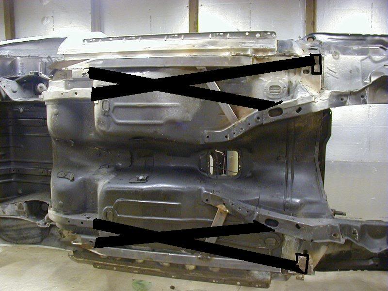
There isnt anything wrong with the perimeter bracing. The only 'real' frame in these cars is in the front, and its only a partial frame, reinforced by the trans tunnel, firewall, and strut towers. Its a true unibody. The rear frame referred to above doesnt really exist, if you look at the picture posted above multiple times you'll notice it pretty much ends where the shock and spring are. While attaching there instead of the outboard location of the rear LCA might be a little better, overall given that the idea is to reinforce the unibody and not the non-existent frame, its kind of a moot point. You basically can consider it as two different channels of thought, one being to connect to and create a frame that does not exist, the other being to reinforce what the factory was using as a 'frame' which is not the floorpan between the 'frame rails' but rather the side rockers under the doors. The difference in the .095 and .120 tubing is also not really worth talking about, even if you double subframe the car you're only going to add another ~10 pounds of weight. Just for curiosity and since I have to work on the car anyway, I took a couple pictures (I'll post later) under my convertible of the rear 'frame rail' and also of where ASC decided to reinforce the car... along the perimeter with a fabbed .083 wall U channel riveted to the car. There may have been other reasons for that, such as ground clearance concerns or they didnt bother designing anything just ran with an idea but I'd like to think that with GM being involved in the matter it was more than just a whim. I can tell you that someone at GM who shall still remain nameless used these 'factory' subframes on coupes that were used in racing, passed off as being installed at the factory using a part that was in fact being used on 'factory' cars even though they were never used on coupes or as far as I know never installed by GM in the Van Nuys GM plant either aside of the few racecars mentioned. I suspect GM did have a hand in telling ASC where to reinforce the car. Another thing to consider is the location does not matter when you're talking about bending of the car F-R, as long as the connectors run F-R. If you're trying to minimize the torsion in the body, you want the connectors as far away from the centerline of the body as possible. Imagine the effort you'd need to use to turn on your typical sprinkler, then imagine the effort if there was a 1' diameter wheel attached to it instead. Its about leverage.
I have a model of a frame I've been using for analysis, I can try some different wall thicknesses and tell you what benefit there is from it. Personally for 10 pounds I'd use the thicker tubing. Regardless, I'll tell you what both will do.
I have a model of a frame I've been using for analysis, I can try some different wall thicknesses and tell you what benefit there is from it. Personally for 10 pounds I'd use the thicker tubing. Regardless, I'll tell you what both will do.
Member
iTrader: (12)
Joined: Sep 2006
Posts: 215
Likes: 0
From: Allentown, PA
Car: 87 Trans am
Engine: 350tpi
Transmission: 6spd
Axle/Gears: 4.10
Re: Sub frames (design rough draft)
I'd have to agree with most of that exept that the rear fram dosent exsist. It definatly does not end at the shock mounts. I have cut apart 2 of these cars and they definatly have a sheet metal box that goes up over the spring and back to the bummper. Hear is a pic of a cutaway over the spring.
Thread Starter
Joined: Dec 2007
Posts: 1,924
Likes: 12
From: Minnesota
Car: 84 camaro, 88 trans am, 98 camaro
Engine: Modded , stock, LSX modded
Transmission: 700r4, 700r4, t-56
Axle/Gears: 327, 308, 373
Re: Sub frames (design rough draft)
no rear sub frame. . . Well im going to see how much material i need and im going to do my design it triangulates and makes more sense
Thread Starter
Joined: Dec 2007
Posts: 1,924
Likes: 12
From: Minnesota
Car: 84 camaro, 88 trans am, 98 camaro
Engine: Modded , stock, LSX modded
Transmission: 700r4, 700r4, t-56
Axle/Gears: 327, 308, 373
Re: Sub frames (design rough draft)
i'm picking up a different dimensions of tubing so i can get an idea and see whats going to work for everything i need to clear. once i decided on what im going to run then i will start on it by next week i hope. i will keep an update on progress here
Supreme Member
Joined: Nov 2007
Posts: 1,092
Likes: 1
From: IL
Car: 88 IROC, 76 Malibu Classic
Engine: 350 TPI, 350
Transmission: 700R4, 4-speed
Axle/Gears: 10 bolt ????
Re: Sub frames (design rough draft)
Mine run right under the floor. The driver side one runs directly under the seat. I welded pieces of angle iron off the sides to provide a place to bolt the seat to the "frame".
At the rear there's quite a bit of fabrication. The ends were notched to angle down. A simple triangle cut to cover the end would work just as good. Because the SFC sits on/under the rear subframe, strips of flat steel were then welded to the sides of the SFC and to the side of those rear sub frames.
The front is a simple diagonal cut and weld to the subframe. Mine might be slightly forward from where I've drawn them to make the SFC straighter.
When I first put them in many years ago, the car still had a single 3" exhaust running roughly where the stock exhaust goes. To clear the exhaust pipe, the passenger side SFC has a c-section cut into it.
One advantage I've had to this style SFC is it allowed me to fabricate different types of tranny mount crossmembers over the years. I simply attached the crossmember to the SFC instead of the terribly designed factory mount points. It was wider but allowed a simple way of easily install and remove the crossmember without having to worry about stripping the mount threads.
As I mentioned above. My front and rear mount points are to the sub frames. All those other mounting points are sheet metal. The goal is to eliminate that huge section of sheet metal between the front and rear with a section of frame to keep the subframes from flexing the body. That one simple strip on both sides completes the frame. If you want to make it stronger, find a way to X the frame between the SFC.
At the rear there's quite a bit of fabrication. The ends were notched to angle down. A simple triangle cut to cover the end would work just as good. Because the SFC sits on/under the rear subframe, strips of flat steel were then welded to the sides of the SFC and to the side of those rear sub frames.
The front is a simple diagonal cut and weld to the subframe. Mine might be slightly forward from where I've drawn them to make the SFC straighter.
When I first put them in many years ago, the car still had a single 3" exhaust running roughly where the stock exhaust goes. To clear the exhaust pipe, the passenger side SFC has a c-section cut into it.
One advantage I've had to this style SFC is it allowed me to fabricate different types of tranny mount crossmembers over the years. I simply attached the crossmember to the SFC instead of the terribly designed factory mount points. It was wider but allowed a simple way of easily install and remove the crossmember without having to worry about stripping the mount threads.
As I mentioned above. My front and rear mount points are to the sub frames. All those other mounting points are sheet metal. The goal is to eliminate that huge section of sheet metal between the front and rear with a section of frame to keep the subframes from flexing the body. That one simple strip on both sides completes the frame. If you want to make it stronger, find a way to X the frame between the SFC.