
'87 Formula Vin H getting the LSx treatment- She's ALIVE! swap docs collection inside

Re: '87 Formula getting the LSx treatment
You've got open/closed backwards, but yes, the resistance checks are right. Open means the circuit has a break in it, closed the circuit is a complete loop
Easier way is to pull the relay, jumper 30 to 87 and see if you've got 12v at the connector under the car near the tank. While you're under there do a resistance test from the ground wire in the same connector to the chassis. That'll rule out a ground being off
Easier way is to pull the relay, jumper 30 to 87 and see if you've got 12v at the connector under the car near the tank. While you're under there do a resistance test from the ground wire in the same connector to the chassis. That'll rule out a ground being off
Thread Starter
Member
iTrader: (3)
Joined: Jul 2008
Posts: 385
Likes: 0
From: ND
Car: 1986 Firebird
Engine: 6.0L LSX
Transmission: 4L60E
Axle/Gears: 3.73
Re: '87 Formula getting the LSx treatment
You're right, I've got the terminology backwards. I'm thinking closed=does not work. When it should be closed=works.
How does one go about checking that the pump is good without pulling the tank?
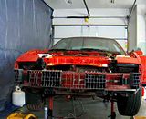
One thing I got to thinking about....The pump itself came with a connector with one red wire and one black wire. Logically one should be positive and one negative (ground). The wires in the original harness (inside the tank) had one black and one gray wire. Again, logically the black should be ground and the gray positive, so that's how I soldered them, unless I assumed wrong and they are switched around?
You can see the connector I'm talking about in the corner of the picture. I hadn't soldered the pump to the connector at this point in the picture

How does one go about checking that the pump is good without pulling the tank?
One thing I got to thinking about....The pump itself came with a connector with one red wire and one black wire. Logically one should be positive and one negative (ground). The wires in the original harness (inside the tank) had one black and one gray wire. Again, logically the black should be ground and the gray positive, so that's how I soldered them, unless I assumed wrong and they are switched around?
You can see the connector I'm talking about in the corner of the picture. I hadn't soldered the pump to the connector at this point in the picture
Last edited by mille_3; Mar 14, 2011 at 02:26 PM.
Joined: Sep 2002
Posts: 3,685
Likes: 10
From: PA
Car: 86 Trans AM
Engine: LS1 (not stock...)
Transmission: Built T56
Axle/Gears: Strange 12-bolt w/ 3.73
Re: '87 Formula getting the LSx treatment
You should be ok on wire colors... Pretty sure mine was gray for power black for ground. Even the 4th gen's tank wiring uses these colors.
If you put 12v and ground to the harness coming off the tank, that should make the pump work. If it doesnt turn on...something is wrong between the plug and the pump. OR the pump is no good. Like I said...you wouldnt be the first.
If you jump the pump and she works...then work your way back. At that point, Ide be looking at the plug between the tank and the body. I remember the body connector for my tank was pretty horrible looking when I did my swap. I ditched it since I went with the 4th gen tank and wiring harness.
J.
Thread Starter
Member
iTrader: (3)
Joined: Jul 2008
Posts: 385
Likes: 0
From: ND
Car: 1986 Firebird
Engine: 6.0L LSX
Transmission: 4L60E
Axle/Gears: 3.73
Re: '87 Formula getting the LSx treatment
Saved for later post
Last edited by mille_3; Mar 15, 2011 at 07:19 AM.
Thread Starter
Member
iTrader: (3)
Joined: Jul 2008
Posts: 385
Likes: 0
From: ND
Car: 1986 Firebird
Engine: 6.0L LSX
Transmission: 4L60E
Axle/Gears: 3.73
Re: '87 Formula getting the LSx treatment
So here's what I found. Ground from the connector on the body side at the tank is good. The gauge works which is coming from the purple wire in the connector. The only wire that is screwing things up is the gray wire. No power.
I tested the pump with a 12V source and the pump comes on. The fuel pump relay works as I can hear it click on and off for about 2 seconds as I turn the ignition. When I crank it comes back on and clicks backs off when the car doesn't start.
SO, this Pin D.....this is my issue. I am not able to find this thing on any schematics to trace it. Where does it go after it leaves C207? Is it a straight shot to the connector at the tank? I don't understand why there is no power, especially since I never touched anything after C207.
I feel like I'm banging my head against a wall. On the bright side, I'm learning this damn car inside and out
Last edited by mille_3; Mar 15, 2011 at 07:33 PM.
Re: '87 Formula getting the LSx treatment
After the C207 it goes through the dash bundle, along the drivers rocker panel, behind the drivers rear seat and to the rear bulkhead, then tank. No connections in between. You can trace it or do the simple method of cut it at the C207 and run a fresh wire external of the harness. Be 100% sure the C207 is getting 12v before you do this

Senior Member
iTrader: (8)
Joined: Sep 2010
Posts: 732
Likes: 0
From: Cincinnati, Ohio
Car: '89 GTA
Engine: 5.7L LS1
Transmission: 4L60E
Axle/Gears: 9 bolt 3.27
Thread Starter
Member
iTrader: (3)
Joined: Jul 2008
Posts: 385
Likes: 0
From: ND
Car: 1986 Firebird
Engine: 6.0L LSX
Transmission: 4L60E
Axle/Gears: 3.73
Re: '87 Formula getting the LSx treatment
It's powered up. The MIL light comes on because I haven't added the ECT wires in to the ECM plug yet. Was waiting on the new sensor and wasn't sure what plug it took so I haven't gotten that done yet. For whatever reason I am not getting 12V past C207. Frustrating to say the least.
Senior Member
iTrader: (8)
Joined: Sep 2010
Posts: 732
Likes: 0
From: Cincinnati, Ohio
Car: '89 GTA
Engine: 5.7L LS1
Transmission: 4L60E
Axle/Gears: 9 bolt 3.27
Re: '87 Formula getting the LSx treatment
It's powered up. The MIL light comes on because I haven't added the ECT wires in to the ECM plug yet. Was waiting on the new sensor and wasn't sure what plug it took so I haven't gotten that done yet. For whatever reason I am not getting 12V past C207. Frustrating to say the least.
Thread Starter
Member
iTrader: (3)
Joined: Jul 2008
Posts: 385
Likes: 0
From: ND
Car: 1986 Firebird
Engine: 6.0L LSX
Transmission: 4L60E
Axle/Gears: 3.73
Re: '87 Formula getting the LSx treatment
The most confusing part about this is that I have tried looking this up in both Mitchell repair and Alldata and neither show the connectors so there is no easy way to trace the wires. On Pin D there is a black/red wire that continues on to the connector at the back by the tank, but nowhere in those diagrams does it show a black/red wire.
Senior Member
iTrader: (8)
Joined: Sep 2010
Posts: 732
Likes: 0
From: Cincinnati, Ohio
Car: '89 GTA
Engine: 5.7L LS1
Transmission: 4L60E
Axle/Gears: 9 bolt 3.27
Re: '87 Formula getting the LSx treatment
According to the pinout in this tread by Pocket:
https://www.thirdgen.org/forums/ltx-...formation.html
Your fuel control should be either pin K, M, or N
https://www.thirdgen.org/forums/ltx-...formation.html
Your fuel control should be either pin K, M, or N
Re: '87 Formula getting the LSx treatment
I broke down and went over to the neighbors house and got my laptop with alldata back
Yeah, not sure what all that stuff is, I'd run a fresh wire from the known good C207 D to the rear bulkhead. According to the diagram, after the 12v goes through the C207 a few times it reaches the C208 (?) before passing through the rear bulkhead and the sender inline connector C313
The description for C208 is LH shroud ahead of center access hole. So, in other words its an inline connector somewhere between the rear bulkhead and the dash. Helpful as ever GM")
Pin L may be your answer
Yeah, not sure what all that stuff is, I'd run a fresh wire from the known good C207 D to the rear bulkhead. According to the diagram, after the 12v goes through the C207 a few times it reaches the C208 (?) before passing through the rear bulkhead and the sender inline connector C313
The description for C208 is LH shroud ahead of center access hole. So, in other words its an inline connector somewhere between the rear bulkhead and the dash. Helpful as ever GM
Pin L may be your answer
Supreme Member
iTrader: (10)
Joined: Oct 2007
Posts: 1,881
Likes: 2
From: Fl.
Car: 83 Trans Am / 96 Jeep XJ
Engine: 355 / 4.0 I6
Transmission: TH350 / Auto
Axle/Gears: 3.23 10-bolt / 4wd
Thread Starter
Member
iTrader: (3)
Joined: Jul 2008
Posts: 385
Likes: 0
From: ND
Car: 1986 Firebird
Engine: 6.0L LSX
Transmission: 4L60E
Axle/Gears: 3.73
Re: '87 Formula Vin H LSx treatment - She's ALIVE. Swap docs inside
SHE'S ALIVE!!!
I'll get a better vid up later. Moved Pin D around until the pump came alive at Pin L. Now I just have to figure out why the tach isn't working.
Click the picture for video
I'll get a better vid up later. Moved Pin D around until the pump came alive at Pin L. Now I just have to figure out why the tach isn't working.
Click the picture for video
Last edited by mille_3; Mar 2, 2014 at 07:27 PM. Reason: updated links
Supreme Member
iTrader: (1)
Joined: Mar 2007
Posts: 1,237
Likes: 7
From: Apopka, Florida
Car: 1989 Pontiac Trans Am GTA
Engine: cammed LS1
Transmission: Monster SS 4L65E
Axle/Gears: 9 bolt posi w/ 3.70 gears
Re: '87 Formula getting the LSx treatment
Woo hoo! Congrats man! I'm glad you got it figured out. On to more fun things 
Congrats man! I'm glad you got it figured out. On to more fun things Joined: Sep 2002
Posts: 3,685
Likes: 10
From: PA
Car: 86 Trans AM
Engine: LS1 (not stock...)
Transmission: Built T56
Axle/Gears: Strange 12-bolt w/ 3.73
Re: '87 Formula getting the LSx treatment
Nice!!! That pesky wiring will get ya every time! Amazing what one wrong pin can do huh? Congrats!
Hearing her fire up and had to be satisfying...I know it kicked me into another gear when I first got mine running!
J.
Hearing her fire up and had to be satisfying...I know it kicked me into another gear when I first got mine running!
J.
Thread Starter
Member
iTrader: (3)
Joined: Jul 2008
Posts: 385
Likes: 0
From: ND
Car: 1986 Firebird
Engine: 6.0L LSX
Transmission: 4L60E
Axle/Gears: 3.73
Re: '87 Formula getting the LSx treatment
 . Once I heard that fuel pump come alive I knew I was home free
 Can someone confirm that the Tach is supposed to be on D6?
Re: '87 Formula Vin H getting the LSx treatment- She's ALIVE! swap docs collection in
Big congrats man! 
Tach is C100 D6 for all 3rd gens 82-92, it never changes. Birds commonly require the tach booster wire because the LS1 PCM output isnt very strong
http://www.lt1swap.com/lsx_tach.htm
I pull off B19 PCM fuse wire with a 680ohm resistor to the tach wire
Once again, congrats! Big hurdle is behind you
Tach is C100 D6 for all 3rd gens 82-92, it never changes. Birds commonly require the tach booster wire because the LS1 PCM output isnt very strong
http://www.lt1swap.com/lsx_tach.htm
I pull off B19 PCM fuse wire with a 680ohm resistor to the tach wire
Once again, congrats! Big hurdle is behind you
Senior Member
iTrader: (8)
Joined: Sep 2010
Posts: 732
Likes: 0
From: Cincinnati, Ohio
Car: '89 GTA
Engine: 5.7L LS1
Transmission: 4L60E
Axle/Gears: 9 bolt 3.27
Re: '87 Formula Vin H getting the LSx treatment- She's ALIVE! swap docs collection in
Awww...you should have put the camera higher. We couldn't see that big grin on your face  . Well done!
. Well done! Senior Member
iTrader: (4)
Joined: May 2006
Posts: 704
Likes: 2
From: Beloeil, Quebec
Car: IROC-Z
Engine: LSx
Transmission: T56
Axle/Gears: Fabbed 9"
Re: '87 Formula Vin H getting the LSx treatment- She's ALIVE! swap docs collection in
Awesome man. well done! best feeling in the world.
Joined: Sep 2005
Posts: 6,258
Likes: 6
From: O'Fallon, MO
Car: 1991 Z28 convertible built 3/1/1990
Engine: Cammed 6.0L LSX
Transmission: T56
Axle/Gears: custom Ford 8.8", 4.10 gears
Re: '87 Formula Vin H getting the LSx treatment- She's ALIVE! swap docs collection in
Big congrats man!!! I know you have to be ecstatic right now!
I can hardly wait to drive mine again, this weather is really starting to get nice again
I can hardly wait to drive mine again, this weather is really starting to get nice again
Thread Starter
Member
iTrader: (3)
Joined: Jul 2008
Posts: 385
Likes: 0
From: ND
Car: 1986 Firebird
Engine: 6.0L LSX
Transmission: 4L60E
Axle/Gears: 3.73
Re: '87 Formula Vin H getting the LSx treatment- She's ALIVE! swap docs collection in
Thanks guys. I can't tell you what a relief it is to know that everything IS wired correctly . There is a reason the camera was set so low, I didn't want to scare anyone with my ugly mug
Pocket, thanks for the link and all the help you have provided throughout this build.
Just have to get things buttoned up, a few things left like y-pipe, sub frame connectors and a bit of clean up and I should be able to "reveal" my secret to my kid
. There is a reason the camera was set so low, I didn't want to scare anyone with my ugly mugPocket, thanks for the link and all the help you have provided throughout this build.
Just have to get things buttoned up, a few things left like y-pipe, sub frame connectors and a bit of clean up and I should be able to "reveal" my secret to my kid
Joined: Sep 2005
Posts: 6,258
Likes: 6
From: O'Fallon, MO
Car: 1991 Z28 convertible built 3/1/1990
Engine: Cammed 6.0L LSX
Transmission: T56
Axle/Gears: custom Ford 8.8", 4.10 gears
Re: '87 Formula Vin H getting the LSx treatment- She's ALIVE! swap docs collection in
I still don't understand how you have kept this a secret from your son?!
Thread Starter
Member
iTrader: (3)
Joined: Jul 2008
Posts: 385
Likes: 0
From: ND
Car: 1986 Firebird
Engine: 6.0L LSX
Transmission: 4L60E
Axle/Gears: 3.73
Re: '87 Formula Vin H getting the LSx treatment- She's ALIVE! swap docs collection in
Joined: Sep 2002
Posts: 3,685
Likes: 10
From: PA
Car: 86 Trans AM
Engine: LS1 (not stock...)
Transmission: Built T56
Axle/Gears: Strange 12-bolt w/ 3.73
Re: '87 Formula Vin H getting the LSx treatment- She's ALIVE! swap docs collection in
I have to admit... with most swaps all I really want to see is the payoff. I want to see it start, drive, exhibit some power...then Im usually happy.
Im still interested in seeing that...but I REALLy want to see how the reveal goes down! I hope you set up a camera or something and post his reaction! I bet you have all sorts of scenarios for showing him the car in your head!
J.
Im still interested in seeing that...but I REALLy want to see how the reveal goes down! I hope you set up a camera or something and post his reaction! I bet you have all sorts of scenarios for showing him the car in your head!
J.
Thread Starter
Member
iTrader: (3)
Joined: Jul 2008
Posts: 385
Likes: 0
From: ND
Car: 1986 Firebird
Engine: 6.0L LSX
Transmission: 4L60E
Axle/Gears: 3.73
Re: '87 Formula Vin H getting the LSx treatment- She's ALIVE! swap docs collection in
lol, yeah I plan on putting the car back together in the next couple of weeks. The weather is getting real nice so once the car is in one piece I will have an excuse to clean the garage. Of course I'll be so "busy" that I will need him to come move his car out of the garage. I'll definitely have the camera set up to catch his reaction......but it will be up to him if he minds that it gets posted. I don't think he will care if I do, but it will be his call.
......but it will be up to him if he minds that it gets posted. I don't think he will care if I do, but it will be his call. 


Member

Joined: Jan 2009
Posts: 143
Likes: 0
Car: 91 Formula
Engine: lq4
Transmission: t-56
Re: '87 Formula Vin H getting the LSx treatment- She's ALIVE! swap docs collection in
Big congrats man!
Tach is C100 D6 for all 3rd gens 82-92, it never changes. Birds commonly require the tach booster wire because the LS1 PCM output isnt very strong
http://www.lt1swap.com/lsx_tach.htm
I pull off B19 PCM fuse wire with a 680ohm resistor to the tach wire
Once again, congrats! Big hurdle is behind you
Tach is C100 D6 for all 3rd gens 82-92, it never changes. Birds commonly require the tach booster wire because the LS1 PCM output isnt very strong
http://www.lt1swap.com/lsx_tach.htm
I pull off B19 PCM fuse wire with a 680ohm resistor to the tach wire
Once again, congrats! Big hurdle is behind you
great thread by the way, thanks for taking the time to document everything.

Member
iTrader: (1)
Joined: Sep 2003
Posts: 455
Likes: 0
Car: 1988 firebird trans am GTA
Engine: 5.7L w/hsr
Transmission: 700r4
Axle/Gears: posi 3.23
Re: '87 Formula Vin H getting the LSx treatment- She's ALIVE! swap docs collection in
seriously, you are freaking awesome man. that zip file just saved me so much work and answered so many questions.. just awesome. thank you!!
Thread Starter
Member
iTrader: (3)
Joined: Jul 2008
Posts: 385
Likes: 0
From: ND
Car: 1986 Firebird
Engine: 6.0L LSX
Transmission: 4L60E
Axle/Gears: 3.73
Re: '87 Formula Vin H getting the LSx treatment- She's ALIVE! swap docs collection in
Re: '87 Formula Vin H getting the LSx treatment- She's ALIVE! swap docs collection in
so pocket, does the tach accept inputs on either the c100 or the c207 next to the old ecm? i am pretty sure i wired mine up at the c207 and it is working. i had my pcm under the dash, so i just attached it there. just another way to do it i think.
Thread Starter
Member
iTrader: (3)
Joined: Jul 2008
Posts: 385
Likes: 0
From: ND
Car: 1986 Firebird
Engine: 6.0L LSX
Transmission: 4L60E
Axle/Gears: 3.73
Re: '87 Formula Vin H getting the LSx treatment- She's ALIVE! swap docs collection in
Decided to tackle the sub frame connectors today. Yet another beat to fit, shim as required, paint to match type day. These connectors (SWracecars) are supposed to be bolt in but aren't. A few minor modifications were required. No big deal but would have been nice if they just bolted in. Evidently all T-top cars have the same issue but this bird had to go the extra step and be "that one" that tech support had never run into. Outside of the minor massaging, these are very nice connectors. I'm happy with them.
The bolt holes don't quite line up. Had to enlarge one and cut open the other.

Same on the drivers side

Passenger side runs into the floor. Out came the BFH tool.
<a href="http://s568.photobucket.com/user/mille_3/media/87%20Bird/HPIM2258.jpg.html" target="_blank"><img src="http://i568.photobucket.com/albums/ss124/mille_3/87%20Bird/th_HPIM2258.jpg" border="0" alt=" photo HPIM2258.jpg" style=""></a>
Floor pad not quite getting to where it needs to be due to the floor pan interference. After a few well placed smacks with the hammer it fit.

Side shot. They hang a bit low but nothing major.

Hawks cross member. Same issue with bolt holes. Nothing lines up and I had to rework it to make it fit. This was the worst bolt.

Just exhaust left and I should be able to do a shake down run in the next couple of weeks
Last edited by mille_3; Mar 2, 2014 at 07:30 PM. Reason: updated links
Member
iTrader: (5)
Joined: Mar 2003
Posts: 409
Likes: 0
From: Cali
Car: '85 Camaro
Engine: LS1
Transmission: T56
Axle/Gears: 3.73
Re: '87 Formula Vin H getting the LSx treatment- She's ALIVE! swap docs collection in
I can't wait till you get this car on the road and test out the tires 
Re: '87 Formula Vin H getting the LSx treatment- She's ALIVE! swap docs collection in
Should have popped for some UMI SFC's. Those sit way too low for my liking. Great build though!
Member


Joined: Jul 2002
Posts: 255
Likes: 9
From: Humid Houston on the Texas coast
Car: '86 Z28
Engine: SDPC TPI 350
Transmission: WC T5
Axle/Gears: 3.23 posi
Re: '87 Formula Vin H getting the LSx treatment- She's ALIVE! swap docs collection in

Mike
Thread Starter
Member
iTrader: (3)
Joined: Jul 2008
Posts: 385
Likes: 0
From: ND
Car: 1986 Firebird
Engine: 6.0L LSX
Transmission: 4L60E
Axle/Gears: 3.73
Re: '87 Formula Vin H getting the LSx treatment- She's ALIVE! swap docs collection in
I'm not sure what the interference is. It is an auto tranny. I spoke with Scott at Swracecars yesterday and he mentioned something interesting about T-top cars. He said that GM swears that the location of the cross member bolt holes are in the exact same location as hard top cars. But from their experience and measurements they have taken for their connector that they build, the bolt holes are slightly off on a t-top.
Thread Starter
Member
iTrader: (3)
Joined: Jul 2008
Posts: 385
Likes: 0
From: ND
Car: 1986 Firebird
Engine: 6.0L LSX
Transmission: 4L60E
Axle/Gears: 3.73
Re: '87 Formula Vin H getting the LSx treatment- She's ALIVE! swap docs collection in
Yeah probably, who knows. I do know that the one I got was way off but I made it work. Got the tach and temp working today. Not ideal to add in the temp sender after the harness is taped up, but fortunately the old harness is right there so it wasn;t a long run. Just exhaust left now.
For those of you guys who have reused your old auto shifter cable. Does that bolt pop out of the plastic holder at the end of the cable? The gear selector on the transmission has a little ball type deal that should snap into the cable. whereas the old transmission bolted to the cable. Mine is a bit dirty and it's hard to tell. I don't want to break it.
For those of you guys who have reused your old auto shifter cable. Does that bolt pop out of the plastic holder at the end of the cable? The gear selector on the transmission has a little ball type deal that should snap into the cable. whereas the old transmission bolted to the cable. Mine is a bit dirty and it's hard to tell. I don't want to break it.
Senior Member
iTrader: (8)
Joined: Sep 2010
Posts: 732
Likes: 0
From: Cincinnati, Ohio
Car: '89 GTA
Engine: 5.7L LS1
Transmission: 4L60E
Axle/Gears: 9 bolt 3.27

Senior Member
iTrader: (8)
Joined: Sep 2010
Posts: 732
Likes: 0
From: Cincinnati, Ohio
Car: '89 GTA
Engine: 5.7L LS1
Transmission: 4L60E
Axle/Gears: 9 bolt 3.27
Re: '87 Formula Vin H getting the LSx treatment- She's ALIVE! swap docs collection in
For those of you guys who have reused your old auto shifter cable. Does that bolt pop out of the plastic holder at the end of the cable? The gear selector on the transmission has a little ball type deal that should snap into the cable. whereas the old transmission bolted to the cable. Mine is a bit dirty and it's hard to tell. I don't want to break it.
Thread Starter
Member
iTrader: (3)
Joined: Jul 2008
Posts: 385
Likes: 0
From: ND
Car: 1986 Firebird
Engine: 6.0L LSX
Transmission: 4L60E
Axle/Gears: 3.73
Re: '87 Formula Vin H getting the LSx treatment- She's ALIVE! swap docs collection in
Re: '87 Formula Vin H getting the LSx treatment- She's ALIVE! swap docs collection in
Use the cable linkage and shifter from the 700R4. Pop the shift arm off the 700R4 trans and install it on the 4L60E. Note how the bracket mounts to the old 700R4. When attached to the 4L60E, it will be one bolt hole forward. It is advised to point the little **** on the shifter arm towards the trans so the cable is closer to the pan than frame rail for more exhaust clearance. You're going to need it

Joined: Mar 2000
Posts: 43,187
Likes: 45
From: Littleton, CO USA
Car: 82 Berlinetta/57 Bel Air
Engine: L92/LQ4 (both w/4" stroke)
Transmission: 4L80E/4L80E
Axle/Gears: 12B-3.73/9"-3.89
I used the Hawks 4L60E crossmember. No alignment problems.
Senior Member
iTrader: (8)
Joined: Sep 2010
Posts: 732
Likes: 0
From: Cincinnati, Ohio
Car: '89 GTA
Engine: 5.7L LS1
Transmission: 4L60E
Axle/Gears: 9 bolt 3.27
Re: '87 Formula Vin H getting the LSx treatment- She's ALIVE! swap docs collection in
Thread Starter
Member
iTrader: (3)
Joined: Jul 2008
Posts: 385
Likes: 0
From: ND
Car: 1986 Firebird
Engine: 6.0L LSX
Transmission: 4L60E
Axle/Gears: 3.73
Re: '87 Formula Vin H getting the LSx treatment- She's ALIVE! swap docs collection in
This is some random image I found on the net. I was too lazy to go ut in the garage and take pictures. I'm talking about the end of the cable where it attaches to the gear selector arm on the transmission itself. The 700R4 cable has a bolt and nut at the end of the cable, whereas the gear selector arm on the 4L60E uses a stud like the one in the bottom of this picture where it seems cobbled together. I already have the cable bracket mounted and all that, just wondering if you guys took the gear selector arm off of the 700R4 as well.
