
Electrical panels

Thread Starter
Moderator


Joined: Jul 1999
Posts: 17,268
Likes: 170
From: 51�N 114�W, 3500'
Car: 87 IROC L98
Engine: 588 Alcohol BBC
Transmission: Powerglide
Axle/Gears: Ford 9"/31 spline spool/4.86
Electrical panels
The thread was started in another forum and it's a good idea. Lets see pictures of your race car wiring panels.
This is my second panel and it's still a rats nest. The first panel was attached to the side of the cage and wasn't much better. I've been picking up new components and plan on doing a complete rewire this winter. I need to make something simple and more organized. I don't even have anything labeled.

I bought one of these that will make using relays much simpler and cleaner.

This is my second panel and it's still a rats nest. The first panel was attached to the side of the cage and wasn't much better. I've been picking up new components and plan on doing a complete rewire this winter. I need to make something simple and more organized. I don't even have anything labeled.
I bought one of these that will make using relays much simpler and cleaner.
Last edited by AlkyIROC; Jan 11, 2010 at 11:13 PM.


Joined: Jan 2004
Posts: 1,761
Likes: 4
From: The "D"
Car: A Portly 85 Z28
Engine: 4.530 X 4.250 BBC
Transmission: under rated for this application
Axle/Gears: also under rated
Re: Electrical panels
Thats a nice looking panel, microsoft??? LoL ! Whats something like that go for if you don`t mind me asking? If it`s reasonable it`s definitely worth a look at. I`m not a fan of those micro relays, changed too many of those, at least on high amp circuts like a/c compressors and starter relays. I have a picture of the panel I did last winter, pretty much everything except the on off switches and the progressive controller for the 1 st stage are on it. it`s aweful but it works and I can fix or change things at the track without an engineers layout table!
P.S> this sits in the passenger footwell and looks a tad bit more clutered installed but you can work with it at the track, and those guys out there that have had a problem at the track with something electrical know what I mean!
P.S> this sits in the passenger footwell and looks a tad bit more clutered installed but you can work with it at the track, and those guys out there that have had a problem at the track with something electrical know what I mean!
Thread Starter
Moderator
Joined: Jul 1999
Posts: 17,268
Likes: 170
From: 51�N 114�W, 3500'
Car: 87 IROC L98
Engine: 588 Alcohol BBC
Transmission: Powerglide
Axle/Gears: Ford 9"/31 spline spool/4.86
Re: Electrical panels
DOS 3.1. It really needs an upgrade. If you think that looks bad, you should see behind the dash for the switches and gauges. Everything works exactly like it's supposed to but it ain't pretty.
I've just spent the last few hours drafting up a schematic on paper for wiring so I'll know what kind of terminal strips I'm going to need to join many of the wires. So far I only have the ignition box and delay box drawn up and that took a couple of hours. Now I need to draw all the switches that control everything, gauges, lights, data recorder, sensors etc. Installing all the components on a panel won't look anything like the schematic but at least the wiring won't be so complicated. I'm glad I don't have to add NOS circuits. I'm also planning on putting labels on all the wire ends under some clear shrink tube and remove all those red, blue and yellow plastic covers on the terminal ends.
I'm planning on mounting everything on the roll cage at the back of the passenger door opening. That way I have easy access to anything with the door open. Right now with the panel mounted under the dash, it's very difficult to reach.
The micro relays are for low amp draw items, lights, ignition etc. Until I finish the schematic, I won't know how many I'll need but I doubt I'll use all 10 circuits. I'll still need a couple of externally mounted relays. I know I need to use one to switch a ground circuit for the transbrake button to the delay box to a voltage circuit for the 2-step in the ignition.
Thread Starter
Moderator
Joined: Jul 1999
Posts: 17,268
Likes: 170
From: 51�N 114�W, 3500'
Car: 87 IROC L98
Engine: 588 Alcohol BBC
Transmission: Powerglide
Axle/Gears: Ford 9"/31 spline spool/4.86
Re: Electrical panels
I went to an electrical supply store twice this week to pick up stuff and still will need more as the project progresses.
I found a perfect aluminum project box for an overhead switch panel. There's enough room for 3 more switches if I need them or maybe a voltage gauge. The backside of the box is attached to the halo bar by two 1-5/8" exhaust clamps (no pics yet). The input power, ground (for the pilot lights) and output wires still need to be installed but probably won't be done until I determine exactly where the circuit panel will go to know the length. The starter button hasn't been installed yet and I screwed up drilling the light holes and drilled one above the start button. I have no idea what to use the hole for yet. Perhaps a dome light but with all the other lights on, I probably won't need it. All the lights are LED and all the switches will activate relays so there's low load on all. The wiring is only 18 gauge. The lights and switches are on 1" centers.
I put a guard over the master switch. With the switch off, it kills power to everything. That allows me to turn on the master switch then crank over the engine before turning on ignition power. The guard prevents hitting it accidentally and easier to locate if it's dark, car filled with smoke etc.
All the switches are upside down. Off is up. I did it like that because of where the power terminal is on the back of the switch. Putting them upside down puts the switch terminal towards the middle and away from the edge of the box. The labels were done with a label maker and clear label tape.
Last edited by AlkyIROC; Oct 27, 2009 at 09:58 PM.

Supreme Member
Joined: Apr 2002
Posts: 4,627
Likes: 3
From: Southwest Florida
Car: projects.......
Re: Electrical panels
^^^clean start on the re-wire there Stephen.
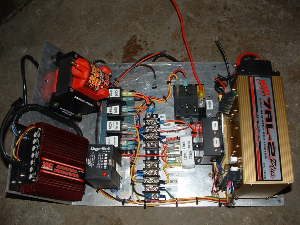
One of two; this one has the fan, water pump(also trans cooler fan), fuel pump and n2o arming(red flip cover near Fluke EGT). The panel is mounted to the pipe via the two hose clamps, loosen them and you can flip it right around to access the wiring. I did this panel seperate as it will come out when the blower motor goes in(not needed). The toggle mounted by itself off the shifter is the "bang button" for purging the n2o.

Don't seem to have a pic of my main panel on my PB account. It's overhead in the left front corner of the cage, single toggle switch for the lights, push button for starting, and upside down mounted cover toggle of ignition on(with it upside down, I can kill the car simply throwing my hand up). There is also a 2-way switch mounted in bottom of it that switches my left steering button back and forth between the line-lock and the t-brake. Right steering wheel button is on the co2 shifter.
I'm **** retentive about wiring, I'll have to get some more pics and post them up.
One of two; this one has the fan, water pump(also trans cooler fan), fuel pump and n2o arming(red flip cover near Fluke EGT). The panel is mounted to the pipe via the two hose clamps, loosen them and you can flip it right around to access the wiring. I did this panel seperate as it will come out when the blower motor goes in(not needed). The toggle mounted by itself off the shifter is the "bang button" for purging the n2o.
Don't seem to have a pic of my main panel on my PB account. It's overhead in the left front corner of the cage, single toggle switch for the lights, push button for starting, and upside down mounted cover toggle of ignition on(with it upside down, I can kill the car simply throwing my hand up). There is also a 2-way switch mounted in bottom of it that switches my left steering button back and forth between the line-lock and the t-brake. Right steering wheel button is on the co2 shifter.
I'm **** retentive about wiring, I'll have to get some more pics and post them up.
Thread Starter
Moderator
Joined: Jul 1999
Posts: 17,268
Likes: 170
From: 51�N 114�W, 3500'
Car: 87 IROC L98
Engine: 588 Alcohol BBC
Transmission: Powerglide
Axle/Gears: Ford 9"/31 spline spool/4.86
Re: Electrical panels
I have more toggle switches mounted on the panel beside the shifter. I have a momentary off switch to kill the power to the vehicle reaction timer. Every now and then it screws up and to reset it you need to kill the power. I didn't want a normal off/on switch and found a perfect switch for a highway truck. It's designed to flash the clearance lights by disrupting the power and works perfect for what I needed.
On the panel is also the bump button for the delay box. I could have mounted it anywhere including on the steering wheel but right under the delay box works. If I want the throttle pedal to fall to the floor before I roll into the beams, I hit the button first. The pedal can also fall to the floor as soon as I push the transbrake button but there's too many things happening quickly to get ready in time so I use the bump button. There's also 2 other seldom used switches mounted there. A switch to turn on or off the 2-step so I can quickly do a full transbrake stall without having to go into the ignition programmer to change the limit and a switch to turn on and off the rpm switch for the air shifter which I still haven't used. I still like slamming that shifter forward with my hand when the shift light comes on
All those switches are minor control switches and are not engine or car related like the switches mounted in the overhead panel above. All the switches could be mounted in the overhead panel but I didn't want unrelated switches in the same panel.
I think I may pick up a new voltage gauge and mount it in blank space of the overhead panel.
Trending Topics
Thread Starter
Moderator
Joined: Jul 1999
Posts: 17,268
Likes: 170
From: 51�N 114�W, 3500'
Car: 87 IROC L98
Engine: 588 Alcohol BBC
Transmission: Powerglide
Axle/Gears: Ford 9"/31 spline spool/4.86
Re: Electrical panels
Switch panel is done except for the starter button which is still in the dash of the car. I figured out what I'm going to do with the extra hole I drilled above the start button. I was thinking of drilling a hole in the side for the harness and after doing a test fit, the harness can easily come out that hole instead. It will be right at the roof diagonal.
Bench test to make sure everything works. The blue and red lights are super bright. Green and amber not so much. Maybe when the battery is charging, they'll be brighter but I doubt it. The gauge light is also on.

Test fit to see how it will look mounted to the halo bar.

Bench test to make sure everything works. The blue and red lights are super bright. Green and amber not so much. Maybe when the battery is charging, they'll be brighter but I doubt it. The gauge light is also on.
Test fit to see how it will look mounted to the halo bar.
Last edited by AlkyIROC; Oct 28, 2009 at 11:30 PM.
Thread Starter
Moderator
Joined: Jul 1999
Posts: 17,268
Likes: 170
From: 51�N 114�W, 3500'
Car: 87 IROC L98
Engine: 588 Alcohol BBC
Transmission: Powerglide
Axle/Gears: Ford 9"/31 spline spool/4.86
Re: Electrical panels
And custom made. There are some really nice switch panels available. Most people see the Moroso or Painless switch panels but one of the nicest ones is from ARC. The ARC panel has programmable switches which control it's own relay board. As nice as all these aftermarket panels are, they'll never do exactly what you want specifically done to your own car plus they are also very expensive compared to how much I've spent throwing this together. I could have went with rocker switches instead of the toggles but it's a lot more work involved and the toggles work just fine.
Picked up a bunch more components today. I'll tackle some of the wiring panel stuff this weekend. Until the relay board arrives, there's only so much I can do.
I spent most of last night going over the schematics I drew up last week to make a new wiring diagram to show a basic layout to determine how many terminal strips I need. Instead of running the wiring from the overhead switch panel directly to the relay board, it will go to a terminal strip which will then have a wiring panel harness going to where it's needed. Should look really sharp when I'm done. After plotting out all the circuits, the 10 circuit relay board will have one 20 amp relay left over for future expansion.
I didn't want to use the typical terminal strip like this although I already have a bunch of them. It requires lots of terminal ends on all the wiring. If I do use one of these, it will be for a common ground point on the wiring panel with loops joining all the terminals.

Instead I'm going with this style. Slide the bare wire into the hole on the side and tighten a screw on the top. I can buy them as 12 connector and easily cut them down to the size I want. I've already made an 8 and 4 for two different circuits. Makes grouping the wires easier.

Should have a bunch more pictures by the end of the weekend but would still like to see other wiring panels.
Picked up a bunch more components today. I'll tackle some of the wiring panel stuff this weekend. Until the relay board arrives, there's only so much I can do.
I spent most of last night going over the schematics I drew up last week to make a new wiring diagram to show a basic layout to determine how many terminal strips I need. Instead of running the wiring from the overhead switch panel directly to the relay board, it will go to a terminal strip which will then have a wiring panel harness going to where it's needed. Should look really sharp when I'm done. After plotting out all the circuits, the 10 circuit relay board will have one 20 amp relay left over for future expansion.
I didn't want to use the typical terminal strip like this although I already have a bunch of them. It requires lots of terminal ends on all the wiring. If I do use one of these, it will be for a common ground point on the wiring panel with loops joining all the terminals.
Instead I'm going with this style. Slide the bare wire into the hole on the side and tighten a screw on the top. I can buy them as 12 connector and easily cut them down to the size I want. I've already made an 8 and 4 for two different circuits. Makes grouping the wires easier.
Should have a bunch more pictures by the end of the weekend but would still like to see other wiring panels.
Thread Starter
Moderator
Joined: Jul 1999
Posts: 17,268
Likes: 170
From: 51�N 114�W, 3500'
Car: 87 IROC L98
Engine: 588 Alcohol BBC
Transmission: Powerglide
Axle/Gears: Ford 9"/31 spline spool/4.86
Re: Electrical panels
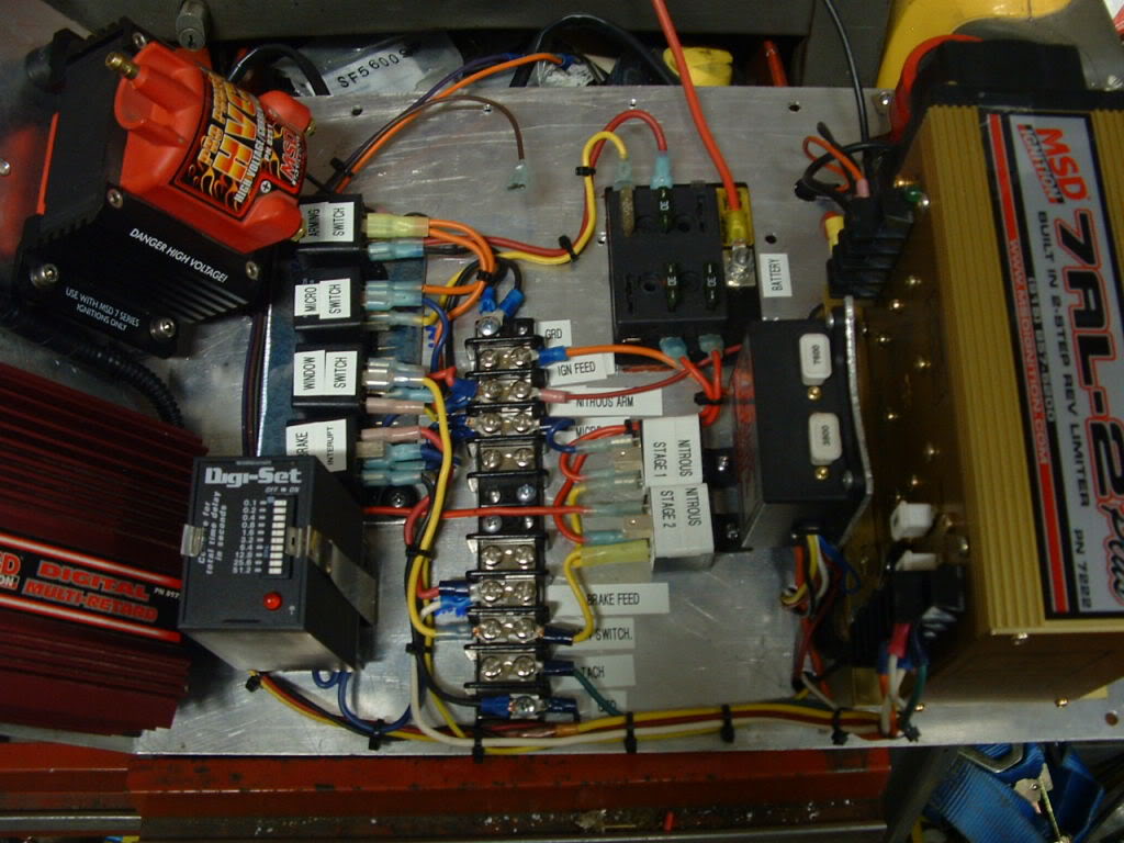
I got a lot done this weekend, pictures later tonight. The overhead switch panel is completed and wired in to a terminal strip on the panel. Turned out better than I expected. I made the wiring panel out of a piece of Lexan and mounted it at the rear of the passenger door opening. That way when the door is open, it's easier to access stuff compared to mounting it at the front of the opening or under the dash. With a door X bar roll cage, access to the front is very limited. The Lexan allows you to see the wiring and components from both sides and there's no chance of anything shorting out to the mount.
As I've already mentioned, I'm using the white plastic terminal strips shown above. This idea has turned out way better than I expected. I can run the wires roughly to where I want and screw them into the proper position on the strip. Once a bundle of wires is routed, I can easily cut them down to make a nice neat bundle without big excess loops at the terminal strips. If you use the eye ring connectors, you'll be using twice as many as you change the wire lengths. I also soldered the ends of the wires before installing them in the terminal strips for a better contact with the retaining screw/clamp. Other than the schematics, none of the wiring has been labeled yet.
I now have 5 pages of schematics for all the different wiring as I've plotted and changed positions and layouts and it's still not complete. Wiring for gauges and sensors hasn't been drawn up on the schematics yet mainly because they don't deal a lot with the wiring panel itself. I started off by making a template of the wiring panel out of poster board to see where components would fit the best. After mounting the Lexan, I've worked out different positions than what I was expecting before attaching them to the Lexan.
The biggest mess is still the ignition box. Holley used weatherpack plugs to connect the ignition to the rest of the car. The plugs are useful for quick disconnect when I'm welding on the car but they're not as simple and clean as an MSD ignition box which has screw connectors right on the box to attach the wiring to.
I'm not expected the relay board to arrive for almost 2 weeks and I need one more stand alone fuse holder which I can pick up tomorrow. I still need to do the wiring for the rest of the car so those components won't slow me down.
Thread Starter
Moderator
Joined: Jul 1999
Posts: 17,268
Likes: 170
From: 51�N 114�W, 3500'
Car: 87 IROC L98
Engine: 588 Alcohol BBC
Transmission: Powerglide
Axle/Gears: Ford 9"/31 spline spool/4.86
Re: Electrical panels
Pictures as promised
Completed switch panel box front, rear and mounted. You can see the harness exiting the switch box and running along the roof diagonal tube. All those switches across the dash will go as will the voltage gauge. I'll probably cut a new piece of aluminum for a new dash or decal over the holes. The grey wiring harness has four 18 gauge wires in it. I couldn't get a harness with eight 18 gauge wires, only 7 wire was available so I decided to use two harnesses. 18 gauge is more than enough for low amp circuits. The entire car doesn't need to be wired with 14 gauge wire. That adds a lot of extra weight.


Here's what the wiring panel looks like so far. The switch panel wiring joins at the top right and will eventually go to the relay board. Two fuse panels are mounted beside it. Under the fuse panels are two 5 volt power supplies to power datalog sensors (MAP, TPS, fuel and oil pressure). The big open area in the middle is where the relay board will go. The two stand alone fuses feed the transbrake and throttle stop.

Completed switch panel box front, rear and mounted. You can see the harness exiting the switch box and running along the roof diagonal tube. All those switches across the dash will go as will the voltage gauge. I'll probably cut a new piece of aluminum for a new dash or decal over the holes. The grey wiring harness has four 18 gauge wires in it. I couldn't get a harness with eight 18 gauge wires, only 7 wire was available so I decided to use two harnesses. 18 gauge is more than enough for low amp circuits. The entire car doesn't need to be wired with 14 gauge wire. That adds a lot of extra weight.
Here's what the wiring panel looks like so far. The switch panel wiring joins at the top right and will eventually go to the relay board. Two fuse panels are mounted beside it. Under the fuse panels are two 5 volt power supplies to power datalog sensors (MAP, TPS, fuel and oil pressure). The big open area in the middle is where the relay board will go. The two stand alone fuses feed the transbrake and throttle stop.
Supreme Member
Joined: Apr 2002
Posts: 4,627
Likes: 3
From: Southwest Florida
Car: projects.......
Re: Electrical panels
Looking very good! Cleanly loomed and yet still easily traceable.
I run toggles, as I hate most rocker switches w/ 5 layer gloves. It's either everything on or everything off - lol.
I run toggles, as I hate most rocker switches w/ 5 layer gloves. It's either everything on or everything off - lol.


Thread Starter
Moderator
Joined: Jul 1999
Posts: 17,268
Likes: 170
From: 51�N 114�W, 3500'
Car: 87 IROC L98
Engine: 588 Alcohol BBC
Transmission: Powerglide
Axle/Gears: Ford 9"/31 spline spool/4.86
Re: Electrical panels
No new pictures. I've redone all the power wiring to the engine compartment, fans, water pump, lights etc. No more multiple butt spliced chunks of wire. I've ripped out all the wiring from under the dash and will probably buy or fabricate a new aluminum dash.
I've been busy all week labeling wires that are already installed. Use a label maker to make the label. Wrap it around the wire then use clear shrink tube over the label. That way I can look at the panel and know exactly what wire is for which circuit.
Should have more pics by the end of the weekend. Relay board finally cleared customs yesterday. It should arrive sometime next week.
Thread Starter
Moderator
Joined: Jul 1999
Posts: 17,268
Likes: 170
From: 51�N 114�W, 3500'
Car: 87 IROC L98
Engine: 588 Alcohol BBC
Transmission: Powerglide
Axle/Gears: Ford 9"/31 spline spool/4.86
Re: Electrical panels
I can't believe how much wiring and fabrication I did over the weekend and it's still not complete. The majority of the wiring under the hood is complete except for the data logging wiring. Most of the wiring to the control panel beside the shifter still needs to be completed. You can see a bundle of wires coming down the door tube. Those are all from under the dash and from the engine compartment and go to the wiring panel which looks like a real mess right now. Once a few more wires are run, I can tidy them all up into a nice harness.
Having to do a complete rewire required a new dash to clean it up. I picked up some .032" aluminum and made a complete new dash. I still need to fabricate a couple more supports for it. There's currently only one on either side. All the gauges and engine sensor wires are done. The tach is all wired up. I installed a second transbrake button on the steering wheel. The one on the left is the one I would normally use. The one on the right is called a bypass button. It allows me to activate the transbrake for backing up or just to bypass the delay in case I screw up on the tree and decide to launch off the bottom bulb. Both buttons use a common ground and send a ground signal to the delay box. I used a 3 wire coiled cable for one input (ground) and 2 outputs (left and right buttons). I wanted some easy way to attach the cable to the dash instead of hard wiring it. I decided to pick up a 1/4" stereo jack and plug and the idea worked out perfectly. I can pull the plug from the dash and completely remove the steering wheel from the car to get it out of the way.
In the dash I have;
Oil pressure warning light connected to a 25 psi sensor
Oil pressure gauge (mechanical)
Oil temperature gauge to a sensor in the pan
Coolant temp sensor (mechanical)
The voltage gauge is now in the overhead switch panel. I've removed the EGT and tranny temp gauges. The EGT I never watched and the tranny doesn't get hot enough unless I'm hotlapping in 30+ C heat which isn't too often. The deep pan I plan on putting on the tranny this winter will help that out.
Of course I had to put the Z28 IROC-Z emblem back on the dash
Thread Starter
Moderator
Joined: Jul 1999
Posts: 17,268
Likes: 170
From: 51�N 114�W, 3500'
Car: 87 IROC L98
Engine: 588 Alcohol BBC
Transmission: Powerglide
Axle/Gears: Ford 9"/31 spline spool/4.86
Re: Electrical panels
Most of the wiring panel is now complete. I need to install another piece of Lexan at the front of the cage to mount the coil and start relay then run the rest of the wiring for the control panel beside the shifter. Wiring for the data log sensors hasn't been done yet either.

Supreme Member
Joined: Apr 2002
Posts: 4,627
Likes: 3
From: Southwest Florida
Car: projects.......
Re: Electrical panels
Now that's looking like it should! - It's amazing how time consuming wiring can be, especially when you really put an effort into doing it right.
Thread Starter
Moderator
Joined: Jul 1999
Posts: 17,268
Likes: 170
From: 51�N 114�W, 3500'
Car: 87 IROC L98
Engine: 588 Alcohol BBC
Transmission: Powerglide
Axle/Gears: Ford 9"/31 spline spool/4.86
Re: Electrical panels
The old wiring was very simplistic. Run them to where they need to go. Splice in with butt connectors if needed. The new wiring is a lot more complicated but it's also a lot more organized. I've probably over-engineered a few of the circuits but at least now I know where everything goes and why. You can see labels on a few of the wires to tell me what they are for. All the relays are marked. The stand alone fuse holders are marked on their tops.
If someone says they'll do a complete race car wiring to look similar to that picture and wants to charge you $1000, it's probably a good deal. I haven't kept track of the hours I've spent hunched over the door bars, running wires, but my lower back is really starting to hurt.
I figure I got about another week before finishing up everything and can test all the circuits just to make sure everything was wired up correctly. Making all the schematics a few weeks ago sure made the wiring a lot easier and even then, I was changing circuits as I started to wire it up.
Things like, I originally planned on having a separate power source for the tach from the fuse panel. Instead of running another wire, the tach now takes it's power off the gauge circuit under the dash. What looked good on paper didn't work out the same once I started wiring. I originally (see picture way above) had a terminal strip mounted beside the 5 volt power supplies but changed the design to eliminate it and run the wires direct. The starter relay has also been removed from this wiring panel and will go on a different one. I needed the room where I had it mounted.
Thread Starter
Moderator
Joined: Jul 1999
Posts: 17,268
Likes: 170
From: 51�N 114�W, 3500'
Car: 87 IROC L98
Engine: 588 Alcohol BBC
Transmission: Powerglide
Axle/Gears: Ford 9"/31 spline spool/4.86
Re: Electrical panels
The wiring is DONE!! I still have one more datalog sensor to install but haven't decided what else to log yet. I still need to mount the O2 sensor but other than that, all the wiring is now finished.
If you look back to the beginning of the thread, you can see what I originally had. It was ugly but it worked.
This is what I now have. Pictures are a little dark. I'll need to take better ones in daylight but until the car is on 4 wheels again, that won't be for a while.


If you look back to the beginning of the thread, you can see what I originally had. It was ugly but it worked.
This is what I now have. Pictures are a little dark. I'll need to take better ones in daylight but until the car is on 4 wheels again, that won't be for a while.
Thread Starter
Moderator
Joined: Jul 1999
Posts: 17,268
Likes: 170
From: 51�N 114�W, 3500'
Car: 87 IROC L98
Engine: 588 Alcohol BBC
Transmission: Powerglide
Axle/Gears: Ford 9"/31 spline spool/4.86
Re: Electrical panels
The few shortcuts I did do, you'll never see. Only a couple of the large gauge wires were spliced instead of running a new long heavy gauge wire, stuff like that. Off and on, this took me close to a month to do and I don't even want to think about the cost. All the wire, connectors, clamps, plastic ties, relay board, switch panel, Lexan, sensors etc probably set me back at least $500, if not more, not counting the stuff I reused. Add in the dozens of hours labor and it's not hard to see why a shop would charge $1000+ to wire a race car.
I did very little for the last week then this weekend, finished it all up. I finished up tonight by removing one of the header tubes and welding on a bung for the O2 sensor. In the top picture, you can see a circle drawn on top of the one header tube. That's where the O2 sensor now sits. With slip on collectors, I didn't want to install the O2 sensor in the collector. The collector isn't a 100% sealed fit and any air leak will cause a false reading.
I still want to change the wiring for the taillights. I currently use the brake light element for taillights during nighttime racing. I want to change it to the regular taillights for less current draw but need to change the light sockets back to the triple wiring style which I don't have right now. I could wire up the third brake light in the spoiler for a rear light but that would mean some sort of plug that would allow me to easily remove the deck lid. Many race cars just use a single tail light so the third brake light would work fine as a light.
I plan on firing the car up within the next week just to check out all the wiring and to see how well the data logger works. I've already powered everything up and it all seems to work fine so far. I've drained the cooling system but it doesn't take much to fill it back up with water not that the alcohol engine really needs any.
I want to pick up some Danger High Voltage decals and stick them on the Lexan that holds the coil, start relay and noise filter capacitor. That coil puts out a full 2 amps of high voltage.
Thread Starter
Moderator
Joined: Jul 1999
Posts: 17,268
Likes: 170
From: 51�N 114�W, 3500'
Car: 87 IROC L98
Engine: 588 Alcohol BBC
Transmission: Powerglide
Axle/Gears: Ford 9"/31 spline spool/4.86
Re: Electrical panels
Designed to remove electrical noise. Normally used for cars with stereo systems but will also remove electrical noise for the electronics I run such as delay box and data logger.
http://www.jegs.com/i/MSD+Ignition/121/8830/10002/-1
Here's another description of that it's used for.
http://www.jegs.com/i/Crane/270/9000-0014/10002/-1
http://www.jegs.com/i/MSD+Ignition/121/8830/10002/-1
Here's another description of that it's used for.
http://www.jegs.com/i/Crane/270/9000-0014/10002/-1
Supreme Member
Joined: Apr 2002
Posts: 4,627
Likes: 3
From: Southwest Florida
Car: projects.......
Re: Electrical panels
Came out very nice. It took me a minute to see the lexan panel; I was thinking, why did he mount them to the door card(lol)?
What o2 sensor/system are you using for methanol? just curious. I was looking at the Fast dual sensor set-up, but have been told my LC-1 will work better with a different sensor(I say better, because I didn't trust the accuracy before).
What o2 sensor/system are you using for methanol? just curious. I was looking at the Fast dual sensor set-up, but have been told my LC-1 will work better with a different sensor(I say better, because I didn't trust the accuracy before).
Thread Starter
Moderator
Joined: Jul 1999
Posts: 17,268
Likes: 170
From: 51�N 114�W, 3500'
Car: 87 IROC L98
Engine: 588 Alcohol BBC
Transmission: Powerglide
Axle/Gears: Ford 9"/31 spline spool/4.86
Re: Electrical panels
Innovate LM-2 system. It uses a VW Bosch wideband sensor. The LM-2 also has 4 data inputs plus a tach input. So far I've installed an oil pressure sensor, fuel pressure sensor and MAP sensor. I haven't decided what else I want to log. I can plug the laptop into the data recorder to watch realtime data or record data onto an SD card which can be put into the laptop to watch or compare a run. The LM-2 also allows playback right on the display screen. There's 2 data outputs so you can use the LM-2 to record, lets say oil pressure, then instead of running more wiring from the sensor, use a transducer style oil pressure gauge to directly show the data right from the data recorder. I doubt I'll ever use the 2 outputs unless I can use a 5v signal to control something. Lets say I'm watching the MAP sensor. At WOT off the line, vacuum drops to zero. As I reach high rpm, the engine load is decreased and vacuum increases. If the voltage produced at a specific vacuum tells me the engine load has decreased, use that information to retard timing or something.
The Lexan is deceiving Once I can get the car outside so I can fully open the door, it will look even better. The nice thing about the Lexan, nothing will ever short out. Bad thing is there's no common ground, not that you want to use aluminum for a ground anyway. Right under the 2 plastic terminal strips on the left, you can just barely see a ground point between the wires. I drilled a hole through the Lexan and installed a #10 screw. The screw is bolted to the Lexan with a nut then all the ground wires attach to the screw and are held on by another nut. A single wire runs from the screw to a common ground on the start relay which, mounted on Lexan, has a larger ground wire going to the roll cage tube on the other side.
The Lexan is deceiving
Once I can get the car outside so I can fully open the door, it will look even better. The nice thing about the Lexan, nothing will ever short out. Bad thing is there's no common ground, not that you want to use aluminum for a ground anyway. Right under the 2 plastic terminal strips on the left, you can just barely see a ground point between the wires. I drilled a hole through the Lexan and installed a #10 screw. The screw is bolted to the Lexan with a nut then all the ground wires attach to the screw and are held on by another nut. A single wire runs from the screw to a common ground on the start relay which, mounted on Lexan, has a larger ground wire going to the roll cage tube on the other side. Last edited by AlkyIROC; Nov 23, 2009 at 01:41 PM.
Supreme Member
Joined: Apr 2002
Posts: 4,627
Likes: 3
From: Southwest Florida
Car: projects.......
Re: Electrical panels
My MSD box is mounted to a lexan panel, and I have grounds, direct power, and ignition power all mounted to it via 1/4 bolts; same method you described.
I'm happy with my LC-1, so I might have to look more into the LM-2. I currently have their(innovative) 4 channel data logger logging MAP, o2, RPM, and EGT(even though I still hit the button on the unit itself, the over-lay graph is nice to have).
I'm happy with my LC-1, so I might have to look more into the LM-2. I currently have their(innovative) 4 channel data logger logging MAP, o2, RPM, and EGT(even though I still hit the button on the unit itself, the over-lay graph is nice to have).
Thread Starter
Moderator
Joined: Jul 1999
Posts: 17,268
Likes: 170
From: 51�N 114�W, 3500'
Car: 87 IROC L98
Engine: 588 Alcohol BBC
Transmission: Powerglide
Axle/Gears: Ford 9"/31 spline spool/4.86
Re: Electrical panels
Just bringing this back from the dead because I fired the car up today to check the data log system. It was really warm today so having the garage door open was good. It still didn't take long for the alcohol fumes to burn my eyes. There wasn't even a breeze to blow the fumes out of the garage.
RPM, O2 and MAP sensor all recorded fine with good results. Oil and fuel pressure were not recording properly. The oil and fuel sensors run off one 5v power supply and the MAP, plus some other sensor in the future, run off another. I traced the problem to two wires mixed up on both pressure sensors. The 5v ref signal was actually going to the sensor ground. Good thing it didn't burn out the 5v power supply.
Because the wiring is color coded at the electrical panels, where it could have been easily switched around, the only other way to fix the mistake is to cut and resolder the wiring at the sensor pigtails or simply switch the pins in the plug. I don't have the tool to remove the pins from the plug at home so I need to do it tomorrow night.
Other than that, everything appears to work fine. I burned off the last of the fuel in the fuel cell tonight so tomorrow I take fuel from the new barrel I picked up at the end of last season. With all the sensors working tomorrow, I want to do a few more tests. The car is still sitting on 4 jackstands and there's too much snow to take it outside.
The overhead switch panel is so much better than having the switches on the dash. It was so easy to just reach up to turn on the master switch, hit the starter button and when the engine started cranking over, flip the ignition switch. With a little bit of gas priming, the engine fired up with less than 30 seconds of total cranking time. It's been a couple of weeks since I fired it up last but it had no coolant in it back then and I didn't want to run it for very long. I only had it running long enough to check the transmission oil level.
Now I need to figure out what to use the last data log sensor port for. I was thinking maybe a TPS but since I launch at WOT, the only good it would do would be to tell me I was pedaling it going down the track. Coolant or oil temperature maybe but in the course of a pass, they don't change very much. About the only thing I may find useful is to use a TPS as a shock travel sensor to record what the rear suspension is doing during a run. The data recorder can't do frequency recording so I can't record driveshaft or wheel speed which would be nice. It can record anything that uses a 5v ref signal. Send the sensor 5v and see how much voltage is returned. Temp sensors are a little different. They just work off a resistance to ground but by putting in a load resistor, you can still get it to record a value for temperature with a little calibration.
The nice thing about the LM-2 is that after you record a run, you pop out the SD card and pop it into a computer to analyze the run. A 1 meg card can hold a lot of runs before you need to remove files. All the log files are saved as the date so it's easy to check back to a specific run. I recorded almost 3 minutes of run time today and the log file is 40KB
Last edited by AlkyIROC; Jan 11, 2010 at 10:25 PM.

Supreme Member
iTrader: (3)
Joined: Jun 2009
Posts: 2,350
Likes: 3
From: Mid West
Car: '87 Camaro
Engine: '92 Carb'd 350
Transmission: 700r4
Axle/Gears: factory stock
Re: Electrical panels
I'll bring mine to ya tomorrow for a complete re-wire!! HAHA!!
How well do you like that Holley Strip box? I ask because I don't know any one using it. The only ones I've seen are MSD & Malory.
How well do you like that Holley Strip box? I ask because I don't know any one using it. The only ones I've seen are MSD & Malory.
Thread Starter
Moderator
Joined: Jul 1999
Posts: 17,268
Likes: 170
From: 51�N 114�W, 3500'
Car: 87 IROC L98
Engine: 588 Alcohol BBC
Transmission: Powerglide
Axle/Gears: Ford 9"/31 spline spool/4.86
Re: Electrical panels
Holley stopped making and supporting them years ago. I bought this one about 10 years ago and it still works fine. If it ever fails, I'll upgrade to an MSD 7AL-3 just to get roughly the same features that this Holley box has. I had the hand controller permanently connected so I could change things like launch rpm while sitting in the staging lanes but decided to leave it off the ignition now. Once the ignition is programmed, it's unusual that I'll change anything once I'm in the staging lanes. Without the handheld controller, you can't change anything.
The only things I might change between rounds is the rev limiters or RPM switches. Burnout and top end limiter are good so launch rpm is the only other limiter. One of the two rpm switches control the air shifter which I still haven't used since I like smacking the shifter forward by hand. The other rpm switch doesn't control anything but I may wire the shift light into it instead of having it run off the tach. I don't think the tach shows the same rpm as the ignition box says it's running at.
As for wiring up somebody elses car, sure. Just leave me $1000 to start with and give me at least a month to do it.
I need to take some new pictures with the fiberglass door behind the panel or better yet, just take the door off. Having all that stuff mounted on Lexan looks so different.
Joined: Jun 2002
Posts: 13,576
Likes: 30
From: Harford County, MD
Car: camaro sportcoupe
Engine: 7.0L
Transmission: G-Force GF5R
Axle/Gears: Moser 9"
Re: Electrical panels
can you use the last sensor port for a wheel speed or driveshaft speed sensor? this would show you where the car had tire spin issues...
Thread Starter
Moderator
Joined: Jul 1999
Posts: 17,268
Likes: 170
From: 51�N 114�W, 3500'
Car: 87 IROC L98
Engine: 588 Alcohol BBC
Transmission: Powerglide
Axle/Gears: Ford 9"/31 spline spool/4.86
Re: Electrical panels
Only if there was some way to take the frequency signal produced by a speed sensor and convert it into a 0-5v signal. I'm sure there's a way but I haven't researched it enough. A driveshaft sensor would be nice to compare it to the engine RPM.
Supreme Member
Joined: Apr 2002
Posts: 4,627
Likes: 3
From: Southwest Florida
Car: projects.......
Re: Electrical panels
Driveshaft or wheel speed are basically the same thing, you just have to do the math for your gear ratio and further for your roll-out if you want to check the tire slip rate. Frequency conversion is possible, the MAF guys have done it to use the LS MAF sensor.
Honestly, $1k would be cheap to get a wriring job like that done, but I noticed you said "to start with", lol.
Honestly, $1k would be cheap to get a wriring job like that done, but I noticed you said "to start with", lol.
Thread Starter
Moderator
Joined: Jul 1999
Posts: 17,268
Likes: 170
From: 51�N 114�W, 3500'
Car: 87 IROC L98
Engine: 588 Alcohol BBC
Transmission: Powerglide
Axle/Gears: Ford 9"/31 spline spool/4.86
Re: Electrical panels
Projects like that I like to think like a lawyer. Give me a retainer fee. If I run out of money, you give me more to continue. Whatever is left over at the end, I'll refund the balance back to you
Why is it that lawyers can do that but nobody else can?
I got the wiring fixed and was running up the engine again tonight. It idles really really rich. Lambda was around .66 at idle even after the engine got some heat in it. When I increased the idle with the throttle to around 2500, the lambda got better to around .73 since opening the throttle slightly leans it down a bit. I'm going to have to leave the barrel valve adjustment where it currently is and open the butterflies a few thou to see how much it will lean it down. Probably going to be a weekend project when I have more time. A perfect idle lambda of 1.0 would be nice but even a slightly rich idle is better than how fat it currently idles at. No wonder my eyes were burning so much.
Oil pressure is now registering exactly what's on the gauge. Fuel pressure is another story. I wanted to record the fuel pressure on the barrel valve outlet. The pressure actually going to the injectors. Even reving the engine up showed no recordable pressure. I bench tested the sensor with air pressure while still connected to the LM-2 and it showed pressure so it must be the pressure port location. The sensor is in the same gallery as all the injector lines. All the lines feed 8 injectors at the same time so there must not be enough of a restriction to create pressure. Looks like I'll need to change the fuel pressure port location. On the outlet side of the pump or with a tee fitting on the inlet side of the barrel valve. That way it will record the actual pressure put out by the pump. I didn't want to do that because when I lift at the top end of the track, the pressure will spike as the pump deadheads.
Supreme Member
iTrader: (3)
Joined: Jun 2009
Posts: 2,350
Likes: 3
From: Mid West
Car: '87 Camaro
Engine: '92 Carb'd 350
Transmission: 700r4
Axle/Gears: factory stock
Re: Electrical panels
Thanks Stepen 87 IROC & Shagwell for the inspiration! I some day will have decent wiring. Spring will bring a start to some other issues before I attack (or GET attacked) the few wiring concerns. Good luck to you guys in the '10 season!!
Thread Starter
Moderator
Joined: Jul 1999
Posts: 17,268
Likes: 170
From: 51�N 114�W, 3500'
Car: 87 IROC L98
Engine: 588 Alcohol BBC
Transmission: Powerglide
Axle/Gears: Ford 9"/31 spline spool/4.86
Re: Electrical panels
Wheee! Fired the car up again after doing a minor throttle linkage adjustment. From a discussion in another forum, where I have the fuel pressure sensor mounted in the barrel valve is fine. Reving up the engine in neutral barely opens the barrel valve so pressure is always low. Tonight I did a quick brake stand to 4500 and fuel pressure recorded fine. Again, the throttle isn't opened very much so pressure was low but it did record something. At WOT and the engine under full load, I'll be able to record exactly how much fuel pressure is getting to the injectors during a run. It will help determine if the pump I have is big enough and can help to adjust the fuel curve. With an open channel in the LM-2, I could record how much pressure is actually coming off the pump but I would need a 250 PSI sensor. At the top end of the track when I lift, the pump will deadhead and spike the pressure. Using only a 100 PSI sensor will break the sensor.
I have a couple more little things to do to the car but I'm basically ready to go racing and only 4+ months before the season starts Other than deciding on what to use the last logging channel for, wiring is now tested and completed.
One thing I didn't test but it should work. With the engine running, turn off the master switch at the rear. The engine should shut off. I'll test that on the weekend.
I have a couple more little things to do to the car but I'm basically ready to go racing and only 4+ months before the season starts
Other than deciding on what to use the last logging channel for, wiring is now tested and completed.One thing I didn't test but it should work. With the engine running, turn off the master switch at the rear. The engine should shut off. I'll test that on the weekend.
Last edited by AlkyIROC; Jan 13, 2010 at 08:24 PM.
Joined: Jun 2002
Posts: 13,576
Likes: 30
From: Harford County, MD
Car: camaro sportcoupe
Engine: 7.0L
Transmission: G-Force GF5R
Axle/Gears: Moser 9"
Re: Electrical panels
man, that's awesome that you're ready so early on this year! i know in the past that you've really struggled with getting the car ready to go before season opener.
mine should be ready to go down the track in a few months.
mine should be ready to go down the track in a few months.
Supreme Member
Joined: Apr 2002
Posts: 4,627
Likes: 3
From: Southwest Florida
Car: projects.......
Re: Electrical panels
Sounds/looks really good. - For note, the pump shouldn't totally "deadhead" when the barrel valve closes, it will just force more through the return jet/pill; thus the pressure will still rise, but not technically deadhead.
Definitely right on the barrel valve vs rpm making "x" pump pressure though. There's a lot of curve to the barrel valve at low throttle levels, thus the minimal rpm increase doesn't really speed the pump up enough to make much variance. - Get that idle leaned out some and you'll likely find a faster 60'.
Definitely right on the barrel valve vs rpm making "x" pump pressure though. There's a lot of curve to the barrel valve at low throttle levels, thus the minimal rpm increase doesn't really speed the pump up enough to make much variance. - Get that idle leaned out some and you'll likely find a faster 60'.
Supreme Member
iTrader: (1)
Joined: Apr 2002
Posts: 4,671
Likes: 1
From: Waterloo, Iowa
Car: 86 firebird with 98 firebird interi
Engine: pump gas 427sbc Dart Lil M 13.5:1
Transmission: Oldani TH400 w/ BTE 9" convertor
Axle/Gears: 31 spline Moser/full spool/4.11Rich
Re: Electrical panels
I'll throw this out there, it was kinda touched on in "the other forum", but I'm working with a fella who has a product that will be able to "sublimate" images onto aluminum, he originally got the idea from the other site in that electrical panel section and saw all the bland panels guys were making, and then using the typical "label maker" to label switches and such.
HERE is a little blog i put together running this new concept through the typical stuff it'd see in a garage setting, just to see what it'd tolerate. As of now we have multiple templates for flat panels that will/could house guages, toggle switches and such. the beauty of it is WHATEVER imagine can be uploaded onto a computer can be transfered onto...better yet INTO the aluminum panel. So done are the days of boring aluminum panels for switch/guage holders, now if you want the panel to look like carbon fiber, the carbon fiber image can be infused onto the panel. If you want to do the layout so all labeling is fused into the carbon fiber panel so you can use any font, any color, any size you can do that too.
Very hard to describe since it's a new concept, but as i type we have numerious panels at a local CNC laser cutting place cutting the base templates we'll be displaying at the Drag Expo ina few weeks, so i will be snapping pictures for reference to help better explain. It would allow companies/people to put their logo's onto their panels along with a background design if they wanted too. biggest thing is a more professional looking panel, and the added benefit of custom designed layouts/verbage/images/etc.....as of late last month this guys company is creating a new website so anybody can get on it and just point/click/drag/drop whatever they want and create it all, hit send and it'll get made and shipped direct. Not really a world changing item, but at the same time it's allowing further customization on the cheap in an extremely durable item
Joined: Mar 2000
Posts: 43,187
Likes: 43
From: Littleton, CO USA
Car: 82 Berlinetta/57 Bel Air
Engine: L92/LQ4 (both w/4" stroke)
Transmission: 4L80E/4L80E
Axle/Gears: 12B-3.73/9"-3.89
HERE is a little blog i put together
 )
) Thread Starter
Moderator
Joined: Jul 1999
Posts: 17,268
Likes: 170
From: 51�N 114�W, 3500'
Car: 87 IROC L98
Engine: 588 Alcohol BBC
Transmission: Powerglide
Axle/Gears: Ford 9"/31 spline spool/4.86
Re: Electrical panels
Newspaper publishers have been printing on aluminum for decades. That's how they made the plates that fit the big drums to print the newsprint. It took chemicals to remove the ink from the plates so they could be reused.
Thread Starter
Moderator
Joined: Jul 1999
Posts: 17,268
Likes: 170
From: 51�N 114�W, 3500'
Car: 87 IROC L98
Engine: 588 Alcohol BBC
Transmission: Powerglide
Axle/Gears: Ford 9"/31 spline spool/4.86
Re: Electrical panels
Hmm. Last night when I fired the car up, it was dark in the car even with the overhead lights on in the garage. Finding the master, start and ignition switches are easy in the dark but when I went to flip the water pump and vaccum pump switches, I had no idea what switches they were. The illuminating lights don't light up the printed text under the switches. I think I may install a small LED on the roll bar roof diagonal that comes on and illuminates the switch panel when the master switch is on.
The majority of the time, I'm racing in the daylight. It's those occasional very late evening track days when I'll need the extra lighting. Maybe use a photosensor from automatic headlights to turn on the LED when it's dark inside the car.
Some of those simple accent lighting LED packages that would do the trick.
Thread Starter
Moderator
Joined: Jul 1999
Posts: 17,268
Likes: 170
From: 51�N 114�W, 3500'
Car: 87 IROC L98
Engine: 588 Alcohol BBC
Transmission: Powerglide
Axle/Gears: Ford 9"/31 spline spool/4.86
Re: Electrical panels
Figured out what the last thing I'm going to log. Went to the local Pick N Pull today and scored a bunch of things I needed including finding a Grand Am with a Supercharged 3.8L that hasn't been stripped yet. I pulled the 2 bar MAP sensor off it and will use it to record the crankcase pressure/vaccum. Although I currently use an electric vaccum pump (late model smog pump) to pull condensation out of the crankcase, it isn't powerful enough and I'd like to know just how much pressure is created inside the crankcase when the engine is under a load. I do have a belt driven vaccum pump that I still need to install if I can ever figure out the best place to put it. The alternator is currently in the way and I don't have a better spot to put it.
The logging information is useless for tuning but will give me a better idea of what's going on inside the engine.
The logging information is useless for tuning but will give me a better idea of what's going on inside the engine.
Thread Starter
Moderator
Joined: Jul 1999
Posts: 17,268
Likes: 170
From: 51�N 114�W, 3500'
Car: 87 IROC L98
Engine: 588 Alcohol BBC
Transmission: Powerglide
Axle/Gears: Ford 9"/31 spline spool/4.86
Re: Electrical panels
I requested a user name change and yes the car in my sig is mine.

Member
Joined: Aug 2009
Posts: 113
Likes: 0
From: Central IL
Re: Electrical panels
After reading the thread of your cage installation, I can see why your car stands so even. The cage stiffened the car a lot didn't it. I don't recall seeing if you put pipe through the firewall out to the front of the inner fender wells??? If you did I'm sorry for missing it, but if you didn't why not?
Thread Starter
Moderator
Joined: Jul 1999
Posts: 17,268
Likes: 170
From: 51�N 114�W, 3500'
Car: 87 IROC L98
Engine: 588 Alcohol BBC
Transmission: Powerglide
Axle/Gears: Ford 9"/31 spline spool/4.86
Re: Electrical panels
The cage has nothing to do with how it wheelstands. The car was pulling hard to the right on launches until I added a rear anti-roll bar. Now it launches straight. The cage does not do through the firewall yet but I do have tubes going from the top of the strut towers down to the front of the frame rails.

