

Hello My car has been over heating, as the temp fan sensor is broken. The previous person who owned my car installed the fan switch fix, but my mechanic disconnected the wires after he fixed it for me, now its overheating again, and i want to know how to get the fan switch working again. So heres what i have, a toggle switch with two wires under my dash running to up near the battery, they end in metal tabs, but at the current time they are just hanging there. i want to know how to connect them back up so i can turn the fan on manually thanks.
I have surched may other posts, but im still confused. what do i have to hook those too wires up to to get my manual fan switch working?
thanks
I have surched may other posts, but im still confused. what do i have to hook those too wires up to to get my manual fan switch working?
thanks


Bad,
What year/engine do you have? There were differences in the fan controls dependign on the year, engine, and fuel systems.
And not to sound like a dumb-a$$, butb why don't you repair the original temperature sensor? A new sensor is about nine bucks...
What year/engine do you have? There were differences in the fan controls dependign on the year, engine, and fuel systems.
And not to sound like a dumb-a$$, butb why don't you repair the original temperature sensor? A new sensor is about nine bucks...
thanks for offering to help me out.. I have a 1990 L98 with only one electric cooling fan, and yes i am going to replace the thingy, but i havent got to town yet, and i need to get the manual overide working first, i did have it repared less than a year ago, but its gone again so i need a knew one.. Damn hedders melt everything.
Bad350,
If you ground the dark green/white wire from the fan relay, the fan should operate. If that doesn't run the fan (with the ignition ON) you may have a fan relay problem. Another temporary way to run the fan constantly is to disconnect the high pressure cutout switch in the air conditioning system, if the car was equipped with A/C. Again, this depends on having a working fan relay and correct fan power wiring.
The CTS and ECM is what controls the cooling fan based on the CTS input. If the CTS isn't reporting the correct temperature to the ECM, you will have other operating problems, like poor mixture control, poor spark timing asvance, incorrect target idle speed, etc.
A CTS is about ten bucks:
Supreme Member
1bad350, i just replced the sensor on the passenger head and also replaced the plug that goes into i t. i am running slp headers and they are to close for comfort on my car. is this the same sensor you are talking about. there are numerous way to get your fans to run all the time or when you manually switch them on but the thing many people dont realize is that when wiring them up to run manually, you have to use good gauge wire with a fuse and relay. just running the fans to a switch hooked inline to a hot lead may cause a fire. i use to have mine run through a switch in my last z but not with my new project. they turn on when there suppose too. my temp doest get rellay high but i havent drivenmy car enough with the new motor to see what it read sin traffic in the hot temps.

Junior Member
I to have same problem with my 87 305 LG4 . Car overheats. The red wire running to my relay switch keeps burning through. I removed the AC on mine would this cause the problem? I,ve considered wiring my fan to a switch or to come on constantly when car is running ,but am not sure how to do this. Would I need to run complete new wiring for fan?

Supreme Member
You have a bad fan relay. If the coolant temp switch is defective you will throw a code and driveability will be affected. The biggest problems TG's have is really crappy electronics. Replace the primary fan relay and go from there. Forget about the crap you read here and other places about secondary fan control circuits, it is not necessary. If all things are working correctly your TG should NEVER overheat. You need more help drop me an E-mail on TGO.

Member
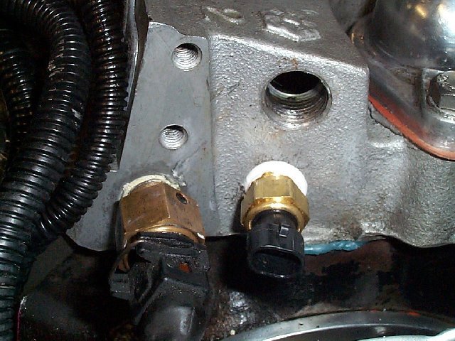
In that pic above, the sensor with out the wires going to it is the CTS right? and what is the other one next to it with the wires connected?
Junior Member
I just replaced the fan relay by the master cylinder on the fire wall. I had to use a butt connector to fix the 16ga. red wire that is power. I started the car ,and when the fan kicked on the red wire started smoking ,and melted the butt connector. I shut the car off. I dont understand what the problem is. Is this the primary relay? Could there be to much voltage running through the red wire? I previously removed the AC. Would this cause the problem? Help

Quote:
Originally posted by Arawn
In that pic above, the sensor with out the wires going to it is the CTS right? and what is the other one next to it with the wires connected?
The other sensor is the Cold Start Injector control/sensor. You should have one of those on a stock '86 TPI.Originally posted by Arawn
In that pic above, the sensor with out the wires going to it is the CTS right? and what is the other one next to it with the wires connected?
- - - - - - - - - - - - - - - - - - - - - - - -
Chevy03,
I'm presuming you have the single electric fan on your '87. Your fan relay is possibly wired incorrectly. The red wire should be larger than AWG 16, and should connect to the fan motor. There should also be a large orange wire adjacent to it. This wire should be protected by a fusible link near the battery, and should have battery power at all times. The relay coil is energized by a tan/white wire and grounded through the ECM by a dark green/white wire.
If your red wire is melting, you are exceeding the current capacity of the wire. If it is truly an AWG 16 wire, it should be capable of carrying 12A continuously without overheating and up to 20A intermittently without smoking the insulation. The factory harness should have been wired with an AWG 12 or larger wire, since the fan motor is rated at 150W (running current of 12.5A with a higher starting current). You either have a failing motor, undersized wire, short in the fan power lead, or a combination of those.

Junior Member
Vader,
I was wrong about the gauge of the red wire. It is 12ga. I am going to see if replacing the fan motor fixes it this weekend. I had a problem with it before when the fan got stuck. It burned the relay. I fixed the fan so it wouldnt hit ,but that one time must have degraded it.I sure hope this fixes the problem. cant wait to drive her. Any sugestions on how to fix the red wire ? It's burned threw about a inch from the relay switch on the firewall. Doesnt give me much to work with. Is there a way to returminate the wire ,and replug in connector?
I was wrong about the gauge of the red wire. It is 12ga. I am going to see if replacing the fan motor fixes it this weekend. I had a problem with it before when the fan got stuck. It burned the relay. I fixed the fan so it wouldnt hit ,but that one time must have degraded it.I sure hope this fixes the problem. cant wait to drive her. Any sugestions on how to fix the red wire ? It's burned threw about a inch from the relay switch on the firewall. Doesnt give me much to work with. Is there a way to returminate the wire ,and replug in connector?
You can splice in a section of wire to repair the harness. When you do so, you'll want the lowest possible resistance connection that you can make, since resistance + current = heat. You should avoid any crimp connectors, and instead strip and solder the splice. Insulate the splice with heat shrink tubing to seal the splice against corrosion. Use a higher temperature solder (a low lead alloy) to make the joint more heat resistant. Use at least the same gauge wire for the splicee section.