


Engine won't idle when warm


Thread Starter
Junior Member
Joined: Jul 2021
Posts: 25
Likes: 0
From: South Australia
Engine won't idle when warm
From Australia restoring a 1988 Iroc z 305 TPI Convertible
When I start the engine from cold it idles ok but when the fans turn on the car will no longer idle. If I shut the car off it starts ok but will only idle at high revs
I have improved things by changing some sensors because they were all original. Maf,o2,temp [ecu],iac,tps
Injectors are around 16 ohms and fuel pressure when running around 35
It is as if something turns on/off around that time. Alternator voltage remains constant.
This car is supposed to be a cruiser. I have a 1968 Big Block as well with a 502.
Hope you guys can help any suggestions appreciated
Regards
Gary
When I start the engine from cold it idles ok but when the fans turn on the car will no longer idle. If I shut the car off it starts ok but will only idle at high revs
I have improved things by changing some sensors because they were all original. Maf,o2,temp [ecu],iac,tps
Injectors are around 16 ohms and fuel pressure when running around 35
It is as if something turns on/off around that time. Alternator voltage remains constant.
This car is supposed to be a cruiser. I have a 1968 Big Block as well with a 502.
Hope you guys can help any suggestions appreciated
Regards
Gary
Thread Starter
Junior Member
Joined: Jul 2021
Posts: 25
Likes: 0
From: South Australia
Re: Engine won't idle when warm
I sprayed carb cleaner into the iac hole. Can the idle air passages be cleaned from the outside, Do you have a procedure for minimum air position.
Thanks in Advance
Thanks in Advance

Moderator


Joined: Jan 2000
Posts: 19,692
Likes: 320
Re: Engine won't idle when warm
Throttle Minimum Air Position
Tools needed:
1. Torx driver # T-20
2. Paper Clip
3. Small Punch
4. Tachometer
GENERAL NOTE: The engine should be at normal operating temperature before performing any adjustments. Never rely on the dash mounted instruments for diagnostics and adjustments. The oil pressure and temperature gauges and the voltmeter and tachometer just aren't calibrated accurately enough for diagnosis, but are a relative indication for monitoring the vehicle while driving.
For this adjustment, the transmission will be in DRIVE while you're under the hood. You will need to securely set the parking brake and block the drive wheels. It would also be a good idea to have an assistant hold the service brake while you perform the adjustments.
In order to successfully complete the adjustment, the IAC air passages and pintle need to be clean. The throttle plates and bores need to be clean as well. If this is not the case, you'll need to remove the air cleaner from TBI engines or the intake air bellows from TPI engines to gain access to the area to be cleaned. A spray-type carburetor cleaner works well for this. Cleaning the IAC passages on a TPI/MAF engine will set a DTC, but we'll be clearing that later. With the engine idling, direct the spray cleaner in to the IAC air passages and around the throttle plates. Shut off the engine and continue cleaning the throttle plates and bores by opening the throttle manually. Once everything is satisfactorily cleaned, replace the air bellows on TPI engines. Many times, this alone can solve IAC/idle speed problems.
If this doesn't solve the problem, you may need to remove and clean the IAC stepper motor. If the IAC appears to be clean and functioning properly, continue with the adjustment procedure.
- - - - - - - - - - - - - - - - - - - - - - - - - - - - - - - - - - - - - - - -
Idle Air Control Cleaning
The IAC can be removed for service. Remove the electrical connector from the IAC. Unscrew the IAC unit from the throttle body.
Very little apparent varnish and dirt accumulation on the IAC pintle rack gear can cause poor or no operation. Below is a comparison between a completely "dead" IAC and a completely funtional one, after cleaning:
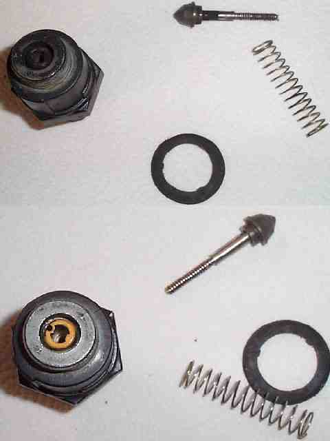
The IAC pintle can be gently rocked back and forth, allowing the spring to extend it until it comes apart. Clean everything with lint-free cloths and a mild solvent. Harsh solvents can affect the insulation of the stepper motor coils. It's generally the dirt and buildup on this worm shaft that causes sluggish IAC operation.
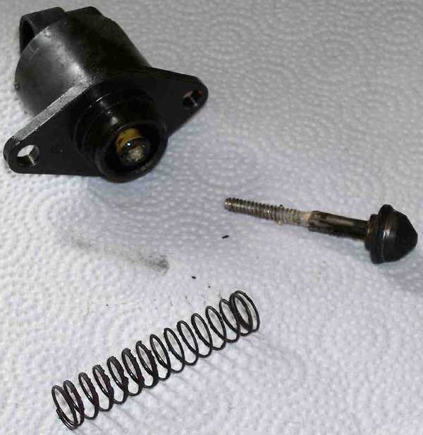
Check the spring free length. Stretch the spring as necessary to get a minimum 2¼" free length. When the worm gear on the pintle shaft is clean and dry, apply one drop of clean light oil to the shaft, align the keyways with the key(s) molded into the IAC body, and work the pintle back into the rack gears of the motor by the same rocking motion. It takes a while to get the pintle back into the worm gears, but the slow process is necessary as it is important to get the pintle fully retracted into the housing, If the pintle is not fully retracted it could be forced against the internal rack gears when reinstalling the IAC unit in the throttle body, thereby destroying the IAC.
While the IAC is out, clean the air passages in the throttle body. The orifice in the TB where the IAC resides is also the seat that the IAC valve closes against, and it can accumulate a lot of carbon, dirt, and debris. The easy way to clean this is with carburetor cleaner and a small stiff brush.
When everything is clean and dry, replace the gasket if it is damaged, apply a little anti-seize to the threads, reinstall, and torque the IAC to the proper specs. (13 ft/lb for '85-'89 , 30 in/lb for 1990-on.) Proceed with setting the TPS and minimum air position.
- - - - - - - - - - - - - - - - - - - - - - - - - - - - - - - - - - - - - - - -
Locate the ALDL connector under the dash panel, in the driver's foot well area. Remove the plastic trim cover (if it is still there).
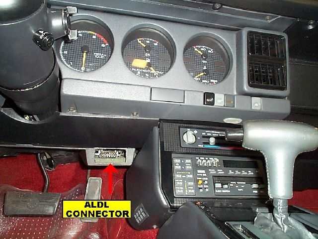
Cut and form a paper clip into a "U" shape. Insert the clip ends into the ALDL in the 'A' and 'B' sockets.
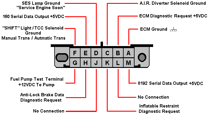
Turn on the ignition, but don't start the engine. This will force the ECM into its diagnostic mode. Wait 30 seconds to allow the IAC pintle to fully extend. Under the hood, remove the electrical connector from the IAC, then turn off the ignition and remove the paper clip jumper from the ALDL. With the IAC pintle fully extended (closed) all idle air will be controlled by the position of the throttle plates.
NOTE - Electronic Spark Timing
Some manuals indicate that the EST bypass connector should be disconnected for this procedure, while some make no mention of it. While timing is a factor in idle speed, the EST should only operate as a function of engine RPM, temperature, and detonation sensor inputs. To remove all doubt, disconnect the EST bypass connector if your car is so equipped. Some TBI and V-6 engines do not have this bypass connector, and therefore must be set with no regard to the EST system. The EST can be bypassed on some cars by grounding the diagnostic terminal at the ALDL and continuing with the procedure, but the fuel mixture will be skewed to the rich side, affecting idle speed as well. In any event, the minimum air position idle speed range is wide enough to allow for some variations. As always, it is best to consult your service manual for the exact procedure for your system.
IMPORTANT REMINDER - Connect a diagnostic tachometer to the ignition coil or ICM terminals for monitoring RPM. Do not rely on the in-dash tachometer since they are almost certainly not accurate, and definitely lack the resolution for proper diagnosis and adjustment.
Locate the Torx screw on the left side of the throttle body. It may still be equipped with a protective metal cap from the factory. This was intended to discourage adjustment. If the cap is present, use a small punch to knock it out. Once the screw is accessible, start the engine, secure the wheels and/or have an assistant hold the service brake, and place the transmission in DRIVE. Adjust the throttle stop to obtain 400 RPM with the transmission in "DRIVE" on an automatic transmission car, 450 in neutral on a manual transmission car, rotating the Torx screw clockwise to raise speed and counter-clockwise to lower speed. Once the idle RPM is set, place the transmission in PARK and turn off the engine.
Re-connect the electrical connector onto the IAC. Reconnect the EST Bypass connector. Remove any jumpers from the ALDL. Start the engine. Idle speed should be governed by the ECM at approximately 600-650 rpm in "DRIVE" (for unmodified cars). Idle speed in NEUTRAL or PARK is less significant, and will be higher.
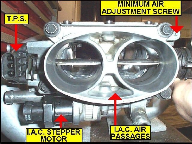
Throttle Position Sensor (TPS)
Tools needed:
1. Digital Volt-Ohm-Meter (VOM)
2. Breakout jumper wires or probes (make your own)
3. OPTION: AutoXray, Tech-II, or similar scanner (will replace the VOM and jumper wires).
Turn on ignition, but don't start the engine.
For the diagnostic scanner method, plug the scanner into the ALDL, establish data communication, and read the TPS voltage. It should be 0.54Volts +/- 0.07 VDC.
For the voltmeter method, connect the VOM leads to the TPS electrical connector terminals ‘A' and ‘B'.
If using a breakout jumper, disconnect the electrical connector from the TPS, install the breakout in-line between the TPS and wiring harness connector. Connect the meter probes to terminals 'A' and 'B' on the connector. (‘B' is the positive connection, ‘A' the signal ground, or negative.) Polarity is not critical if using a digital voltmeter as the meter should indicate positive or negative voltage.
With probes: If you have very slender probes on your VOM, you can back-probe the TPS connector while it is attached to the TPS. If you have made probe extensions of large dressmakers pins or a similar item, you can back-probe the connector as well. Connect the meter probes to terminals 'A' and 'B' on the connector.
Turn on the ignition to read the TPS output voltage at the idle position. The reading should be 0.54VDC +/- 0.07VDC. The ideal is the center of the range, 0.54VDC for a stock engine. To adjust the output voltage, loosen the two Torx screws holding the TPS to the throttle body, and slightly rotate the TPS up or down, reading the voltage until it comes into specification. Tighten screws. Using the throttle lever, rotate the throttle to WOT (wide open throttle). The TPS voltage should be over 4.0 volts. Close the throttle again, and then slowly open it to WOT, observing the voltage reading. It should increase progressively and in a steadcy, linear fashion. If the voltage indication sticks or jumps or falls off at all while doing this check, the TPS sensor may be failing and could be a cause of stumbling and driveability problems.
After achieving the desired setting, turn off the ignition switch. Remove all jumpers or the scanner and reconnect the TPS connector as required.
Reinitializing the ECM
If you set an error code (DTC) during the procedure, the SES light should be illuminated on the dash. This ECM retains DTC data for the previous 50 engine starts, so the codes will eventually be cleared. If you want more immediate results, after shutting down the engine disconnect the negative battery terminal for five minutes. This will clear the ECM of all diagnostic trouble codes. Clearing the ECM also clears any data learned about your engine, and clears the radio presets. If you have a Delco-Loc or Theft Loc II radio, make sure you follow the procedure to unlock the radio protection before disconnecting the battery. This five minutes is also just about long enough to clean both battery cables. Reconnect the battery. When you first start the engine after clearing the ECM, the engine will operate with base parameters programmed into the ECM PROM. These parameters may not be optimum for your engine, but the ECM will enter a Block Learn Mode soon after the engine is warm and enters Closed Loop Mode. The ECM will write new data tables specific to your engine and will eventually rely on those tables instead of the base tables of the factory program. You can expedite this process by driving the car for 20 minutes under varying conditions to allow the ECM to initialize. Or you can wait and drive the car normally at your convenience. The BLM tables are constantly being updated as sensor input ranges change, but the greatest change will occur within the first twenty minutes of Closed Loop operation.
Tools needed:
1. Torx driver # T-20
2. Paper Clip
3. Small Punch
4. Tachometer
GENERAL NOTE: The engine should be at normal operating temperature before performing any adjustments. Never rely on the dash mounted instruments for diagnostics and adjustments. The oil pressure and temperature gauges and the voltmeter and tachometer just aren't calibrated accurately enough for diagnosis, but are a relative indication for monitoring the vehicle while driving.
For this adjustment, the transmission will be in DRIVE while you're under the hood. You will need to securely set the parking brake and block the drive wheels. It would also be a good idea to have an assistant hold the service brake while you perform the adjustments.
In order to successfully complete the adjustment, the IAC air passages and pintle need to be clean. The throttle plates and bores need to be clean as well. If this is not the case, you'll need to remove the air cleaner from TBI engines or the intake air bellows from TPI engines to gain access to the area to be cleaned. A spray-type carburetor cleaner works well for this. Cleaning the IAC passages on a TPI/MAF engine will set a DTC, but we'll be clearing that later. With the engine idling, direct the spray cleaner in to the IAC air passages and around the throttle plates. Shut off the engine and continue cleaning the throttle plates and bores by opening the throttle manually. Once everything is satisfactorily cleaned, replace the air bellows on TPI engines. Many times, this alone can solve IAC/idle speed problems.
If this doesn't solve the problem, you may need to remove and clean the IAC stepper motor. If the IAC appears to be clean and functioning properly, continue with the adjustment procedure.
- - - - - - - - - - - - - - - - - - - - - - - - - - - - - - - - - - - - - - - -
Idle Air Control Cleaning
The IAC can be removed for service. Remove the electrical connector from the IAC. Unscrew the IAC unit from the throttle body.
Very little apparent varnish and dirt accumulation on the IAC pintle rack gear can cause poor or no operation. Below is a comparison between a completely "dead" IAC and a completely funtional one, after cleaning:
The IAC pintle can be gently rocked back and forth, allowing the spring to extend it until it comes apart. Clean everything with lint-free cloths and a mild solvent. Harsh solvents can affect the insulation of the stepper motor coils. It's generally the dirt and buildup on this worm shaft that causes sluggish IAC operation.
Check the spring free length. Stretch the spring as necessary to get a minimum 2¼" free length. When the worm gear on the pintle shaft is clean and dry, apply one drop of clean light oil to the shaft, align the keyways with the key(s) molded into the IAC body, and work the pintle back into the rack gears of the motor by the same rocking motion. It takes a while to get the pintle back into the worm gears, but the slow process is necessary as it is important to get the pintle fully retracted into the housing, If the pintle is not fully retracted it could be forced against the internal rack gears when reinstalling the IAC unit in the throttle body, thereby destroying the IAC.
While the IAC is out, clean the air passages in the throttle body. The orifice in the TB where the IAC resides is also the seat that the IAC valve closes against, and it can accumulate a lot of carbon, dirt, and debris. The easy way to clean this is with carburetor cleaner and a small stiff brush.
When everything is clean and dry, replace the gasket if it is damaged, apply a little anti-seize to the threads, reinstall, and torque the IAC to the proper specs. (13 ft/lb for '85-'89 , 30 in/lb for 1990-on.) Proceed with setting the TPS and minimum air position.
- - - - - - - - - - - - - - - - - - - - - - - - - - - - - - - - - - - - - - - -
Locate the ALDL connector under the dash panel, in the driver's foot well area. Remove the plastic trim cover (if it is still there).
Cut and form a paper clip into a "U" shape. Insert the clip ends into the ALDL in the 'A' and 'B' sockets.
Turn on the ignition, but don't start the engine. This will force the ECM into its diagnostic mode. Wait 30 seconds to allow the IAC pintle to fully extend. Under the hood, remove the electrical connector from the IAC, then turn off the ignition and remove the paper clip jumper from the ALDL. With the IAC pintle fully extended (closed) all idle air will be controlled by the position of the throttle plates.
NOTE - Electronic Spark Timing
Some manuals indicate that the EST bypass connector should be disconnected for this procedure, while some make no mention of it. While timing is a factor in idle speed, the EST should only operate as a function of engine RPM, temperature, and detonation sensor inputs. To remove all doubt, disconnect the EST bypass connector if your car is so equipped. Some TBI and V-6 engines do not have this bypass connector, and therefore must be set with no regard to the EST system. The EST can be bypassed on some cars by grounding the diagnostic terminal at the ALDL and continuing with the procedure, but the fuel mixture will be skewed to the rich side, affecting idle speed as well. In any event, the minimum air position idle speed range is wide enough to allow for some variations. As always, it is best to consult your service manual for the exact procedure for your system.
IMPORTANT REMINDER - Connect a diagnostic tachometer to the ignition coil or ICM terminals for monitoring RPM. Do not rely on the in-dash tachometer since they are almost certainly not accurate, and definitely lack the resolution for proper diagnosis and adjustment.
Locate the Torx screw on the left side of the throttle body. It may still be equipped with a protective metal cap from the factory. This was intended to discourage adjustment. If the cap is present, use a small punch to knock it out. Once the screw is accessible, start the engine, secure the wheels and/or have an assistant hold the service brake, and place the transmission in DRIVE. Adjust the throttle stop to obtain 400 RPM with the transmission in "DRIVE" on an automatic transmission car, 450 in neutral on a manual transmission car, rotating the Torx screw clockwise to raise speed and counter-clockwise to lower speed. Once the idle RPM is set, place the transmission in PARK and turn off the engine.
Re-connect the electrical connector onto the IAC. Reconnect the EST Bypass connector. Remove any jumpers from the ALDL. Start the engine. Idle speed should be governed by the ECM at approximately 600-650 rpm in "DRIVE" (for unmodified cars). Idle speed in NEUTRAL or PARK is less significant, and will be higher.
Throttle Position Sensor (TPS)
Tools needed:
1. Digital Volt-Ohm-Meter (VOM)
2. Breakout jumper wires or probes (make your own)
3. OPTION: AutoXray, Tech-II, or similar scanner (will replace the VOM and jumper wires).
Turn on ignition, but don't start the engine.
For the diagnostic scanner method, plug the scanner into the ALDL, establish data communication, and read the TPS voltage. It should be 0.54Volts +/- 0.07 VDC.
For the voltmeter method, connect the VOM leads to the TPS electrical connector terminals ‘A' and ‘B'.
If using a breakout jumper, disconnect the electrical connector from the TPS, install the breakout in-line between the TPS and wiring harness connector. Connect the meter probes to terminals 'A' and 'B' on the connector. (‘B' is the positive connection, ‘A' the signal ground, or negative.) Polarity is not critical if using a digital voltmeter as the meter should indicate positive or negative voltage.
With probes: If you have very slender probes on your VOM, you can back-probe the TPS connector while it is attached to the TPS. If you have made probe extensions of large dressmakers pins or a similar item, you can back-probe the connector as well. Connect the meter probes to terminals 'A' and 'B' on the connector.
Turn on the ignition to read the TPS output voltage at the idle position. The reading should be 0.54VDC +/- 0.07VDC. The ideal is the center of the range, 0.54VDC for a stock engine. To adjust the output voltage, loosen the two Torx screws holding the TPS to the throttle body, and slightly rotate the TPS up or down, reading the voltage until it comes into specification. Tighten screws. Using the throttle lever, rotate the throttle to WOT (wide open throttle). The TPS voltage should be over 4.0 volts. Close the throttle again, and then slowly open it to WOT, observing the voltage reading. It should increase progressively and in a steadcy, linear fashion. If the voltage indication sticks or jumps or falls off at all while doing this check, the TPS sensor may be failing and could be a cause of stumbling and driveability problems.
After achieving the desired setting, turn off the ignition switch. Remove all jumpers or the scanner and reconnect the TPS connector as required.
Reinitializing the ECM
If you set an error code (DTC) during the procedure, the SES light should be illuminated on the dash. This ECM retains DTC data for the previous 50 engine starts, so the codes will eventually be cleared. If you want more immediate results, after shutting down the engine disconnect the negative battery terminal for five minutes. This will clear the ECM of all diagnostic trouble codes. Clearing the ECM also clears any data learned about your engine, and clears the radio presets. If you have a Delco-Loc or Theft Loc II radio, make sure you follow the procedure to unlock the radio protection before disconnecting the battery. This five minutes is also just about long enough to clean both battery cables. Reconnect the battery. When you first start the engine after clearing the ECM, the engine will operate with base parameters programmed into the ECM PROM. These parameters may not be optimum for your engine, but the ECM will enter a Block Learn Mode soon after the engine is warm and enters Closed Loop Mode. The ECM will write new data tables specific to your engine and will eventually rely on those tables instead of the base tables of the factory program. You can expedite this process by driving the car for 20 minutes under varying conditions to allow the ECM to initialize. Or you can wait and drive the car normally at your convenience. The BLM tables are constantly being updated as sensor input ranges change, but the greatest change will occur within the first twenty minutes of Closed Loop operation.
Thread Starter
Junior Member
Joined: Jul 2021
Posts: 25
Likes: 0
From: South Australia
Re: Engine won't idle when warm
Thanks Vader
I found some problems which I have fixed
Connections on fuel pump relay-- Fitted new relay
Dirty connection on oil safety switch temp bypass -ordered new one
Followed the setting up procedure notice revs high after iac setting done but had to do it with dizzy connected then setup tps.
Have fixed quite a few issues but not the main one. I cant drive this car at the moment waiting for panels to come back from the paint shop
So remaining issue is if you idle the car up to temp when the fans start it loses idle and stalls. Sounds like fuel but isn't because I can still hear the pump running.
I can sometimes simulate the fault by turning the headlight on and loading the motor but not always and I assume the fans have more inrush current, Could the dizzy be faulty and playing up when the voltage spikes
I will wait to see what ideas you have.
Regards
Gary
I found some problems which I have fixed
Connections on fuel pump relay-- Fitted new relay
Dirty connection on oil safety switch temp bypass -ordered new one
Followed the setting up procedure notice revs high after iac setting done but had to do it with dizzy connected then setup tps.
Have fixed quite a few issues but not the main one. I cant drive this car at the moment waiting for panels to come back from the paint shop
So remaining issue is if you idle the car up to temp when the fans start it loses idle and stalls. Sounds like fuel but isn't because I can still hear the pump running.
I can sometimes simulate the fault by turning the headlight on and loading the motor but not always and I assume the fans have more inrush current, Could the dizzy be faulty and playing up when the voltage spikes
I will wait to see what ideas you have.
Regards
Gary

Sponsor

Joined: Nov 2008
Posts: 1,529
Likes: 50
From: Rockville Centre, NY
Re: Engine won't idle when warm
From Australia restoring a 1988 Iroc z 305 TPI Convertible
When I start the engine from cold it idles ok but when the fans turn on the car will no longer idle. If I shut the car off it starts ok but will only idle at high revs
I have improved things by changing some sensors because they were all original. Maf,o2,temp [ecu],iac,tps
Injectors are around 16 ohms and fuel pressure when running around 35
It is as if something turns on/off around that time. Alternator voltage remains constant.
This car is supposed to be a cruiser. I have a 1968 Big Block as well with a 502.
Hope you guys can help any suggestions appreciated
Regards
Gary
When I start the engine from cold it idles ok but when the fans turn on the car will no longer idle. If I shut the car off it starts ok but will only idle at high revs
I have improved things by changing some sensors because they were all original. Maf,o2,temp [ecu],iac,tps
Injectors are around 16 ohms and fuel pressure when running around 35
It is as if something turns on/off around that time. Alternator voltage remains constant.
This car is supposed to be a cruiser. I have a 1968 Big Block as well with a 502.
Hope you guys can help any suggestions appreciated
Regards
Gary
Thread Starter
Junior Member
Joined: Jul 2021
Posts: 25
Likes: 0
From: South Australia
Re: Engine won't idle when warm
Hi Southbay
Yes I did ohm them when hot but all seemed to be 15-16 ohm. What symptoms do you get when the injectors are faulty. I also emailed you guys for a recommendation and quote for injectors plus anything else I need. One plug is broken and would need priority mail.
Thanks
Gary
Yes I did ohm them when hot but all seemed to be 15-16 ohm. What symptoms do you get when the injectors are faulty. I also emailed you guys for a recommendation and quote for injectors plus anything else I need. One plug is broken and would need priority mail.
Thanks
Gary
Trending Topics
Sponsor
Joined: Nov 2008
Posts: 1,529
Likes: 50
From: Rockville Centre, NY
Re: Engine won't idle when warm
Hey Gary....15-16 ohms when hot is fine. Usually when the coil is failing on the stock injectors most of the problem occurs when they are hot.
I think i had mentioned a gasket kit and fuel rail orings.
You will need a set of 19's. Go to my website and check out these sku numbers. They are the 19lb injectors we carry:
sku: 4228
sku: 1008
sku: 4024
...let me know if you are interested in any of the parts because all thirdgen members receive 10% off.
I think i had mentioned a gasket kit and fuel rail orings.
You will need a set of 19's. Go to my website and check out these sku numbers. They are the 19lb injectors we carry:
sku: 4228
sku: 1008
sku: 4024
...let me know if you are interested in any of the parts because all thirdgen members receive 10% off.
Sponsor
Joined: Nov 2008
Posts: 1,529
Likes: 50
From: Rockville Centre, NY
Re: Engine won't idle when warm
Please do me a favor....from this moment on...please do not send messages through our website. You are not the first person to have this issue. We're in the process of building a new website. The site is done, however we are making revisions to the site to make sure it's ready to launch. Either give us a call or message us directly through email. Really sorry for the inconvenience.
In the meantime is there something we can help you with?
In the meantime is there something we can help you with?

Thread
Thread Starter
Forum
Replies
Last Post