

How to adjust Idle on my 87 TPI Trans Am


Thread Starter
Junior Member
Joined: Mar 2001
Posts: 96
Likes: 0
From: New Britain Ct, 06052
How to adjust Idle on my 87 TPI Trans Am
Hey, i just bought a 52mm throttle body, and after starting the car back up i noticed the idle quite low, something like maybe 600 and like 4oo- 500 in gear, i have a slight cam and pulleys so the car just runs at a low choppy idle. When i got my car dynoed a few months ago he adjusted the idle to about like 900 in park and a consistant 700 in gear. The car also ran better after the idle bump, it seemed i went through the RPM'S quiker and smoother, as for now it seems to drag to get up to the desired RPM range. How is the idle set, i know theres that IAC motor, is there a special way to compute the new idle into the computer or what, if anyone knows let me know please, Thank You

Moderator


Joined: Jan 2000
Posts: 19,653
Likes: 309
87,
The target hot idle speed is programmed in the ECM PROM. The ECM will do evertying it can to maintain that idle speed.
You can set the minimum air position and TPS voltage to specifications so the ECM can control the idle properly.
Throttle Minimum Air Position
Tools needed:
1. Torx driver # T-20
2. Paper Clip
3. Small Punch
4. Tachometer
GENERAL NOTE: The engine should be at normal operating temperature before performing any adjustments. Never rely on the dash mounted instruments for diagnostics and adjustments. The oil pressure and temperature gauges and the voltmeter and tachometer just aren't calibrated accurately enough for diagnosis, but are a relative indication for monitoring the vehicle while driving.
For this adjustment, the transmission will be in DRIVE while you're under the hood. You will need to securely set the parking brake and block the drive wheels. It would also be a good idea to have an assistant hold the service brake while you perform the adjustments.
In order to successfully complete the adjustment, the IAC air passages and pintle need to be clean. The throttle plates and bores need to be clean as well. With a new TB, there should be no dirt in the passages, but a used IAC may need some attention.
Cut and form a paper clip into a "U" shape. Insert the clip ends into the ALDL in the 'A' and 'B' sockets. Turn on the ignition, but don't start the engine. This will force the ECM into its diagnostic mode. Wait 30 seconds to allow the IAC pintle to fully extend. Under the hood, remove the electrical connector from the IAC, then turn off the ignition and remove the paper clip jumper from the ALDL. With the IAC pintle fully extended (closed) all idle air will be controlled by the position of the throttle plates. Some manuals indicate that the EST bypass connector should be disconnected for this procedure, while some make no mention of it. While timing is a factor in idle speed, the EST should only operate as a function of engine RPM, temperature, and detonation sensor inputs. To remove all doubt, disconnect the EST bypass connector is your car is so equipped. Some TBI and V-6 engines do not have this bypass connector, and therefore must be set with no regard to the EST system. The EST can be bypassed on some cars by grounding the diagnostic terminal at the ALDL and continuing with the procedure, but the fuel mixture will be skewed to the rich side, affecting idle speed as well. In any event, the minimum air position idle speed range is wide enough to allow for some variations. As always, it is best to consult your service manual for the exact procedure for your system.
Locate the Torx screw on the left side of the throttle body. It may be equipped with a protective metal cap from the factory. This was intended to discourage adjustment. If the cap is present, use a small punch to knock it out. Once the screw is accessible, start the engine and place the transmission in DRIVE. Adjust the throttle stop to obtain 400 RPM with the transmission in "DRIVE" on an automatic transmission car, 450 in neutral on a manual transmission car, rotating the Torx screw clockwise to raise speed and counter-clockwise to lower speed. Once the idle RPM is set, place the transmission in PARK and turn off the engine.
Re-connect the electrical connector onto the IAC. Start engine. Idle speed should be governed by the ECM at approximately 600-650 rpm in "DRIVE" (for unmodified cars). Idle speed in NEUTRAL or PARK is less significant, and will be higher.
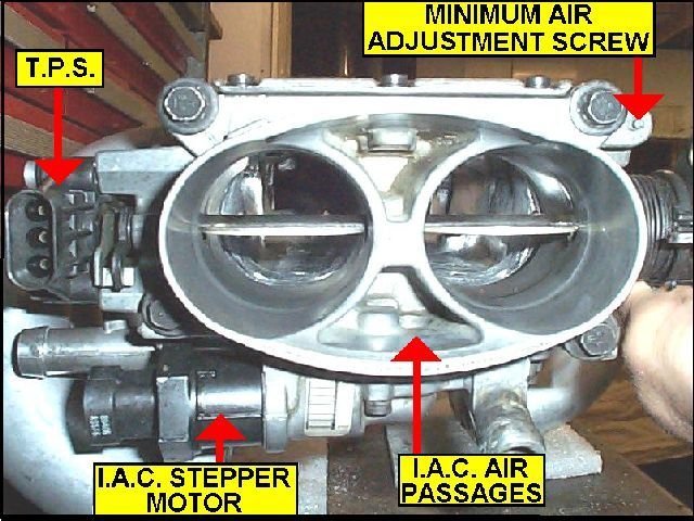
Throttle Position Sensor (TPS)
Tools needed:
1. Digital Volt-Ohm-Meter (VOM)
2. Breakout jumper wires or probes (make your own)
3. AutoXray, Diacom, or similar scanner will replace the VOM and jumper wires.
Turn on ignition, but don't start the engine.
With a diagnostic scanner: plug in the scanner and read the TPS voltage. It should be 0.54Volts +/- 0.07 VDC.
Connect the VOM to the TPS electrical connector terminals ‘A' and ‘B'.
With a breakout jumper: Disconnect the electrical connector from the TPS. Install the breakout in-line, between the TPS and wiring harness connector. Connect the meter probes to terminals 'A' and 'B' on the connector. (‘B' is the positive connection, ‘A' the signal ground, or negative.)
With probes: If you have very slender probes on your VOM, you can back-probe the TPS connector while it is attached to the TPS. If you have made probes of large dressmakers pins or a similar item, you can back-probe the connector as well. Connect the meter probes to terminals 'A' and 'B' on the connector.
Turn on the ignition to read the TPS output voltage at the idle position. The reading should be 0.54VDC +/- 0.07VDC. The ideal is the center of the range, 0.54VDC for a stock engine. To adjust the output voltage, loosen the two Torx screws holding the TPS to the throttle body, and slightly rotate the TPS up or down, reading the voltage until it comes into specification. Tighten screws. Using the throttle lever, rotate the throttle to WOT (wide open throttle). The TPS voltage should be over 4.0 volts. Close the throttle again, and then slowly open it to WOT, observing the voltage reading. It should increase progressively and in a linear fashion. If it sticks or jumps or falls off at all while doing this check, the TPS sensor may be failing and could be a cause of stumbling and driveability problems.
After achieving the desired setting, turn off the ignition switch. Remove all jumpers or the scanner and reconnect the TPS connector as required. Drive the car for twenty minutes under varying loads and speeds to rewrite the ECMs BLM tables.
------------------
Later,
Vader
------------------
"Get UP - Drop the bombshell!"
Adobe Acrobat Reader
The target hot idle speed is programmed in the ECM PROM. The ECM will do evertying it can to maintain that idle speed.
You can set the minimum air position and TPS voltage to specifications so the ECM can control the idle properly.
Throttle Minimum Air Position
Tools needed:
1. Torx driver # T-20
2. Paper Clip
3. Small Punch
4. Tachometer
GENERAL NOTE: The engine should be at normal operating temperature before performing any adjustments. Never rely on the dash mounted instruments for diagnostics and adjustments. The oil pressure and temperature gauges and the voltmeter and tachometer just aren't calibrated accurately enough for diagnosis, but are a relative indication for monitoring the vehicle while driving.
For this adjustment, the transmission will be in DRIVE while you're under the hood. You will need to securely set the parking brake and block the drive wheels. It would also be a good idea to have an assistant hold the service brake while you perform the adjustments.
In order to successfully complete the adjustment, the IAC air passages and pintle need to be clean. The throttle plates and bores need to be clean as well. With a new TB, there should be no dirt in the passages, but a used IAC may need some attention.
Cut and form a paper clip into a "U" shape. Insert the clip ends into the ALDL in the 'A' and 'B' sockets. Turn on the ignition, but don't start the engine. This will force the ECM into its diagnostic mode. Wait 30 seconds to allow the IAC pintle to fully extend. Under the hood, remove the electrical connector from the IAC, then turn off the ignition and remove the paper clip jumper from the ALDL. With the IAC pintle fully extended (closed) all idle air will be controlled by the position of the throttle plates. Some manuals indicate that the EST bypass connector should be disconnected for this procedure, while some make no mention of it. While timing is a factor in idle speed, the EST should only operate as a function of engine RPM, temperature, and detonation sensor inputs. To remove all doubt, disconnect the EST bypass connector is your car is so equipped. Some TBI and V-6 engines do not have this bypass connector, and therefore must be set with no regard to the EST system. The EST can be bypassed on some cars by grounding the diagnostic terminal at the ALDL and continuing with the procedure, but the fuel mixture will be skewed to the rich side, affecting idle speed as well. In any event, the minimum air position idle speed range is wide enough to allow for some variations. As always, it is best to consult your service manual for the exact procedure for your system.
Locate the Torx screw on the left side of the throttle body. It may be equipped with a protective metal cap from the factory. This was intended to discourage adjustment. If the cap is present, use a small punch to knock it out. Once the screw is accessible, start the engine and place the transmission in DRIVE. Adjust the throttle stop to obtain 400 RPM with the transmission in "DRIVE" on an automatic transmission car, 450 in neutral on a manual transmission car, rotating the Torx screw clockwise to raise speed and counter-clockwise to lower speed. Once the idle RPM is set, place the transmission in PARK and turn off the engine.
Re-connect the electrical connector onto the IAC. Start engine. Idle speed should be governed by the ECM at approximately 600-650 rpm in "DRIVE" (for unmodified cars). Idle speed in NEUTRAL or PARK is less significant, and will be higher.
Throttle Position Sensor (TPS)
Tools needed:
1. Digital Volt-Ohm-Meter (VOM)
2. Breakout jumper wires or probes (make your own)
3. AutoXray, Diacom, or similar scanner will replace the VOM and jumper wires.
Turn on ignition, but don't start the engine.
With a diagnostic scanner: plug in the scanner and read the TPS voltage. It should be 0.54Volts +/- 0.07 VDC.
Connect the VOM to the TPS electrical connector terminals ‘A' and ‘B'.
With a breakout jumper: Disconnect the electrical connector from the TPS. Install the breakout in-line, between the TPS and wiring harness connector. Connect the meter probes to terminals 'A' and 'B' on the connector. (‘B' is the positive connection, ‘A' the signal ground, or negative.)
With probes: If you have very slender probes on your VOM, you can back-probe the TPS connector while it is attached to the TPS. If you have made probes of large dressmakers pins or a similar item, you can back-probe the connector as well. Connect the meter probes to terminals 'A' and 'B' on the connector.
Turn on the ignition to read the TPS output voltage at the idle position. The reading should be 0.54VDC +/- 0.07VDC. The ideal is the center of the range, 0.54VDC for a stock engine. To adjust the output voltage, loosen the two Torx screws holding the TPS to the throttle body, and slightly rotate the TPS up or down, reading the voltage until it comes into specification. Tighten screws. Using the throttle lever, rotate the throttle to WOT (wide open throttle). The TPS voltage should be over 4.0 volts. Close the throttle again, and then slowly open it to WOT, observing the voltage reading. It should increase progressively and in a linear fashion. If it sticks or jumps or falls off at all while doing this check, the TPS sensor may be failing and could be a cause of stumbling and driveability problems.
After achieving the desired setting, turn off the ignition switch. Remove all jumpers or the scanner and reconnect the TPS connector as required. Drive the car for twenty minutes under varying loads and speeds to rewrite the ECMs BLM tables.
------------------
Later,
Vader
------------------
"Get UP - Drop the bombshell!"
Adobe Acrobat Reader
Last edited by Vader; Mar 31, 2018 at 10:22 AM. Reason: Updated links

Thread
Thread Starter
Forum
Replies
Last Post
theshackle
Tech / General Engine
4
Sep 17, 2020 08:26 AM
86IROC112
Engine/Drivetrain/Suspension Parts for Sale
4
Aug 17, 2015 02:00 PM
Sanjay
Engine/Drivetrain/Suspension Parts for Sale
1
Aug 12, 2015 03:41 PM