When you click on links to various merchants on this site and make a purchase, this can result in this site earning a commission. Affiliate programs and affiliations include, but are not limited to, the eBay Partner Network.
Tech / General EngineIs your car making a strange sound or won't start? Thinking of adding power with a new combination? Need other technical information or engine specific advice? Don't see another board for your problem? Post it here!
There are many ways to find out what pushrod length works best in your engine. There are many different methods and tools available. Everyone always seems to be concerned about getting the sweep directly on top of the valve tip but it's the smallest sweep possible as long as it's not at the edge of the tip.
Found this today showing how to measure for proper pushrod length. For the average person, it's a little complicated since there's a bit of math involved but if you do it this way, your pushrod length will be exactly where you need it. They are using lightweight checking springs so even a hydraulic lifter won't collapse under the spring pressure.
I've watched that video. Certainly a different approach and one that's better than painting the valve tip and running the engine through several dozen cycles.
Personally, I've taken to Jim Miller's mid lift method of determining the ideal geometry and subsequent correct pushrod length.
You guys with shaft mounted rockers have it easy by comparison.
Here's a run down of my setup.
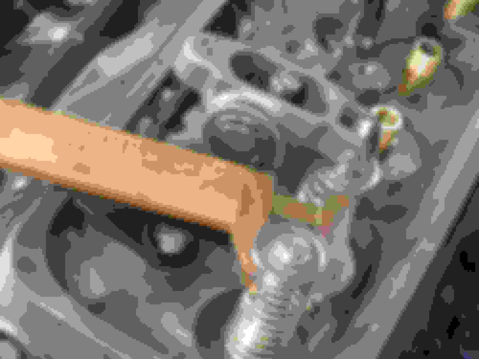
I use an old (wooden) caliper as a jig to establish a reference plane that's perpendicular to the valve stem. If the valve spring retainer had a perfectly flat surface (top side) rather that the slightly concave profile that you can see, the jig wouldn't be necessary and measurements could be taken from the retainer.
Using the jig as support, a measurement is taken from the surface of the reference plane (caliper) to the centre line of the rocker trunnion. In this case, to make measurements easier, I used a piece of material that would allow an easy visual. The material is then measured. The 3/8" allen wrench simplified things here.
A similar measurement is taken from the reference plane to the centre of the roller tip. This is measured with verniers.
This is with the lifter on the base circle of the cam. Obviously the valve will be closed. The difference between what's measured at the trunnion and what's measured at the rocker tip should equal half of the net lift if the pushrod length is correct.
It's really very simple to get it all figured once the measurements can be taken accurately. The rocker locks need not be installed as the engine doesn't have to be rotated. If a flat spring retainer is used, then the actual running springs can be installed and the dimensional accuracy is even more precise.
To verify the results, I still run through a few cycles with the valve tips painted. With this particular combination, the sweep is less than .030". As the contact patch becomes narrower, the rocker tip advances towards the exhaust side. Most bail out here with concerns of running off the edge and fall short of what is ideal. It was necessary to use a .050" backset rocker to get the rocker tip centred on the valve.
As about as good as it gets. The slightly tapered appearance of the contact patch was remedied with the use of adjustable guide plates.
My shaft rockers are a little bit easier but it still uses a special supplied tool and some math. Like you said, still better than painting the valve tip to see where the witness mark is.
In the end, proper valvetrain geometry will probably not have the witness mark directly in the center of the valve tip.
I'm in total agreement with everything you say.
I was editing my post as you entered yours.
To get the contact patch centred, it was necessary to use Crower's .050" backset rocker arms. It moves the rocker arm closer to the intake valve side and compensates for properly sized pushrods. It seems an unfortunate situation that must be addressed. I've personally seen a lot a SBC heads brought back to the machine shop for new guides just for this very reason. Guys will give up on pushrod length because they're concerned with the contact approaching the exhaust side of the valve tip.
It's much better to have contact not centred and narrow than the other way around. It's not only the valve guide wear that's a concern here because with incorrect geometry, the information transferred from the cam to the valve is lacking and performance will suffer. Been there, witnessed that exact situation.
Thanks for posting that video and bringing that subject up. Seems very timely as there are a few guys who are that stage in their builds right now. Hopefully they can take something from this and not ruin what they've worked hard to achieve.
I think one of the worst situations isn't the sweep area not centered but having the rocker sitting off the side slightly. Self aligning rockers correct this problem but heads with pushrod guides still don't always position the rocker exactly where it needs to be. My old BBC heads had pushrod guides as all BBC do and I cut and repositioned a couple of them to help with rocker alignment.
When I installed shaft rockers on my heads, it really repositioned the rockers directly over the valves. It corrected them so much that I had to modify a couple of pushrod passages through the head so that the pushrods didn't make contact. I also went with larger diameter pushrods and a heavier wall which didn't help either but I think even stock width pushrods wouldn't have cleared. End result has the rocker tip directly over the valve stem and the shaft rockers don't move side to side. The larger pushrod limits how much they distort especially when there's over 700 pounds spring pressure when the valves are open.
One nice thing about shaft rockers, I don't need to use a stud girdle and tall rocker covers to cover them all up. Bad thing is the cost. Shaft rockers are out of most peoples budget range.
For the typical street car, just proper geometry with some pedestal rockers is enough.
Taking it a step further, if the rocker is angled, that is it doesn't sit square to the engine centre line, then the geometry becomes very complex. Contact with the valve tip is no longer even. This can be seen in the last picture posted in my first reply above. I took a lot of time with adjustable guide plates (after that picture was taken) to ensure that the rocker roller tip was flat on the valve tip. Seeing as the roller is wider than the valve stem, there's some for adjustment here. However, as in the case of your BBC, pushrod binding became an issue. There is contact with the guide plate naturally but also with the hole in the cylinder head. If I were to do it again, I would mock things up first and modify the head for additional clearance. As it is, I'll have to keep an eye out for evidence of the pushrod binding when I do my inspection. It's a good thing the pushrods have the black coating on them as this allows for witness marks to be left behind wherever there's contact.
It's a lot of work to get it right but with anticipated 6500 RPM shifts and cross country trips planned again, I don't want to have to rebuild these heads for the third time.
Yup. Don't need to buy brand name checking springs. They only need to be strong and long enough to keep the valve closed. Harbor Freight, Home Depot etc might even have something.
VGT everywhere! I was going to build a thread of my own but this will do.
A word of caution about checking springs. Since they don't load the valvetrain as does the actual running spring, the results will be slightly off the optimal. It's been suggested in excess of .050" in some cases.
This is lifted from Miller's paper on VGT.
"I should add one other point here. Everything is “net.” So if you have those cute little “checker springs” laying around, find some other use for them, because outside of holding a valve in a head for display where someone can use their finger pressure to push the valve open, they have little use. You need the REAL running springs for any geometry setup. The same goes for checking flex or piston to valve clearance or anything else critical. Checking springs ADD about .040” (or more) NET valve lift to your engine. Or, another way to say it is you will LOSE .040” or more NET valve lift when you put the heads together with the running springs, compared to whatever you measured using the checking springs. This is true across the board, flat tappet cams, roller cams, aluminum rockers, steel rockers – it makes no appreciable difference."
One of the benefits of Miller's approach is that the actual springs can be used. No rocker lock nut either as the rocker can rest on the pushrod and valve. It's only measurements that are needed and no cycling is required.
I've revisited my own geometry and used a large flat washer between the retainer and running spring so as to establish a reference plane in place of the old caliper shown in the pictures. The Comp retainers don't have a flat top surface to measure from so I needed some kind of platform to work from.
I ended up using the light springs after as I switched from Comp Pro Magnum rockers to Crower's backset rocker so I could observe the differences between the two a little more clearly while running the engine through a few cycles.
At any rate, I don't expect anyone to really appreciate this approach and it's accuracy until they've seen more that few heads trashed because it's been done wrong. My current set of heads is on it's third set of guides and second set of intake valves. Partly due to high mileage and XFI cam lobes (guide set number two and intake valves) but mostly from improper pushrod length (but that's another story and one that comes from swapping short blocks with different deck heights and changing lifters with different seat heights and not revisiting the VGT).
That video from STUPID TECHNOLOGIES is a set up for the novice enthusiast. The video fails to show the novice how to get the cam lobe to 50% lift.. And that takes tools for a cam follower to nail 50% lift on the lobe you are working on - along with the skills to use them .
No way do you need that technique for modest cams under 0.500" lift like 9 out of 10 owners here have! All that most here will need is the simple p-rod length checking tool from MOROSO or ProForm - 10 bucks there about and maybe 10 minutes work.
That STUPID TECHNOLOGIES trolls many, many forums insisting that video is necessary method. And I challenged that actor to provide a method to demonstrate how to find the required 50% valve lift point (and hold it in too) but he never has.
Using a cam lift >0.550" you definitely need a better method/tool than a checker tool. But if trying that video method the first time you ever set-up your valve train you are definitely getting set up all right. You will spend a whole lot more money and time than you need to if you're valve lift is modest - like most street cams are.
Stupid Technologies is trolling around the internet looking to make a business reputation. Mostly at the expense of naive beginning enthusiast. Any business that has to troll the internet for business is amateur and opportunistic with too much free time and to little sales.
Forget everything you know or think you know about valve train geometry. If you use Miller's mid-lift method there is no guesswork. Full running springs are used. No need to cycle the engine through several rotations looking at "witness marks".
100% accurate.
I'm only saying because I've tried many methods of working this geometry out. After reading Miller's paper, it became very clear. So much so that I uncovered other flaws that would lead to additional complexities if trying to nail things perfectly, which should be the target anyway. Why compromise even a little?
Regarding the lift, sadly it's the enthusiast with the 9 out of 10 cam that probably has the most trouble. These are the guys who end up back at the machine shop with wasted valve guides and no idea what happened.
Here's a link the paper I'm talking about. It's well worth the read and it covers a lot of territory. Not just VGT setup but the reasons for it and what happens if you neglect to give it the proper attention.
I strongly suggest reading it to anyone who has any notion of getting into this subject. Even those who feel they are well informed are bound to take something from it.
In case the link skinnyz provided above dies in the future for whatever reason, here is the .PDF. Hopefully not breaking any rules here. This PDF is much easier to print and read. Especially Thx to Jim Miller for sharing his knowledge too!
ETA: BTW, when I picked up my AFR210's from my machine shop after I requested they swap out the 220lb springs for 175lb springs for my hydraulic roller cam with race hydraulic lifters, I asked the cylinder head dude if he thought my CompCams adjustable pushrod would be able to hold up to the 175lb stress of checking pushrod length. He said yes, turning the engine over by hand, this shouldn't be a problem.
Last edited by UltRoadWarrior9; 09-29-2016 at 06:44 PM.
If u have to use 0.050" backset rocker arms on a modest lift cam u have something very wrong.
Well for cams with 0.500" lift or less all you need is a P-rod checker tool and a feeler gauge. No calipers, no geometry marks, no light test springs, no 5 page procedure and works with any spring retainer. I dont know why those with so much experience try to make it so difficult for those with first time experience. I can understand a more complicated procedure for those high lift cams but for the entry level performance cam install the new enthusiast is getting led right over a cliff.
Why is this necessary? Cant you qualify your method for larger cam lifts?
That's not the case at all. This is why the backset rocker exists.
Here's the deal. Most enthusiasts don't know they have the geometry wrong. It doesn't manifest itself until the guides are done prematurely. The only way to tell is to measure. No checking tool. No light springs. Just a pair of calipers and a machinist ruler.
It's a statement of fact that SBC have an issue in this area once aftermarket parts have been added. High ratio rocker arms and higher lift cams all conspire to get things out of position.
I challenge you to show me a build along those lines that has correct geometry, that is the rocker arm is exactly 90 degrees to the valve stem at mid lift )which is THE MOST IMPORTANT element) and the contact point is not excessively offset towards the exhaust side
.The only argument here is what you consider excessive. To me, .050" is a lot.
What do you say is larger lift? Over .500"? .600"?
It doesn't matter. The mid-lift method is appropriate for any cam. What's more, it's probably the easiest method going.
Read the paper. There's a lot of back story that you can skip over but the tech is invaluable.
A little additional information to add to the above.
We've found that the brand of rocker makes a difference even if the advertised ratios are the same. The 355 in question here had a contact point that was close to the exhaust side of the valve. This was with Comp Pro Magnum 1.6 ratio rockers. Using Crowers .050" backset 1.6 rocker yielded a sweep that was too far inboard. However, using Crowers traditional trunnion resulted in a centred contact area. ALL results were achieved via the mid-lift method and ALL had the narrowest possible sweep. The sweep was done for two reasons. One: To verify correct geometry in support of measurements. That is, the narrowest sweep possible and two: to determine where on the valve tip contact was being made.
And..regarding the pushrod checking tool. You might as well throw it away. Unless the tool is exactly the same configuration as the rocker you're getting (which it isn't) its a total waste of money. If the geometry changes between manufacturers, which it most certainly does, how can the tool be in any way reliable?
As for leading newbies off a cliff, quite the opposite. Knowledge is power. Embrace it. They should learn the CORRECT way.
Changing a cam with a different lift does not give you a higher lobe. Lobe height is all the same or very close to it. Making a higher lobe will make it difficult to install into the block. How do you get higher lift? You machine the base circle of the lobe. With a lower base circle, the pushrod will need to be longer to maintain the same geometry.
Have the engine rebuilt and the deck surface gets machined. Head is now slightly closer to the crank centerline. You need shorter pushrods. Mill the head for squareness or more compression and you need shorter pushrods. Change the thickness of the head gasket?
Different heads such as Vortec or any aftermarket head and where the valve sits in the head may be slightly higher or lower to an OEM head and you need different length pushrods. Every time the valve seats are cut, the valve tip moves higher. Maybe you have longer than stock valves so you can use bigger springs with more pressure.
All these changes will change the pushrod geometry. If all you are doing is a simple rebuild using factory parts, then slap those stock pushrods back in and away you go but as soon as you start changing things, the geometry of the valves needs to be checked because it will probably be incorrect.
I have a lot of different length pushrods. Mainly from cam swaps and head swaps. Final pushrods ordered were when I went to shaft rockers because the shaft rockers corrected the poor angles of the pedestal rockers and the pushrod length also changed.
What of the argument 'incorrect pushrod length' "...wears the pushrod guides..." when using a full roller setup? I can undersand a stock GM type rocker arm pushing and shoving a valve, but a full roller setup doing similar damage?
Changing a cam with a different lift does not give you a higher lobe. Lobe height is all the same or very close to it. Making a higher lobe will make it difficult to install into the block. How do you get higher lift? You machine the base circle of the lobe. With a lower base circle, the pushrod will need to be longer to maintain the same geometry.
Have the engine rebuilt and the deck surface gets machined. Head is now slightly closer to the crank centerline. You need shorter pushrods. Mill the head for squareness or more compression and you need shorter pushrods. Change the thickness of the head gasket?
Different heads such as Vortec or any aftermarket head and where the valve sits in the head may be slightly higher or lower to an OEM head and you need different length pushrods. Every time the valve seats are cut, the valve tip moves higher. Maybe you have longer than stock valves so you can use bigger springs with more pressure.
All these changes will change the pushrod geometry. If all you are doing is a simple rebuild using factory parts, then slap those stock pushrods back in and away you go but as soon as you start changing things, the geometry of the valves needs to be checked because it will probably be incorrect.
I have a lot of different length pushrods. Mainly from cam swaps and head swaps. Final pushrods ordered were when I went to shaft rockers because the shaft rockers corrected the poor angles of the pedestal rockers and the pushrod length also changed.
I couldn't agree more. Add to that list: different lifters have different seat heights.
One of my failures came from a combination of many of the factors you've listed above. I had excellent VGT, through luck more than anything as, at the time I knew really nothing about it and I went for the centred on the valve tip approach. As it turned out, that was also the narrowest sweep (or very nearly so) and that engine went tens of thousand of miles without issue.
Fast forward to the original shortblock getting new heads (with .100" longer valves) and I revisited the VGT and came up with a new length. Makes sense. But...that shortblock was giving me grief so out it went. The new block had been decked about .025". New lifters with a different seat height were also added (Comps short travel tool steel units). Not revisiting the VGT cost me a set of guides after a few thousand miles. They were completely smoked.
Since then I have a very strict approach to how I measure VGT and it's the mid-lift method all the way. No silly checking tool which may provide a perfectly inaccurate result. No sweep method back and forth looking for a pattern that's suitable. I measure and confirm.
Lessons learned and I'm only trying to spread the news. But people are stubborn. People are lazy. And people are afraid of a little math. It is geometry after all and it can intimidate some.
Originally Posted by UltRoadWarrior9
What of the argument 'incorrect pushrod length' "...wears the pushrod guides..." when using a full roller setup? I can undersand a stock GM type rocker arm pushing and shoving a valve, but a full roller setup doing similar damage?
 09-26-2016, 09:03 PM