More than you ever wanted to know about BACKPRESSURE...
 12-30-2005, 08:24 PM
#1
Supreme Member
Thread Starter
iTrader: (3)
Join Date: May 2004
Location: Brighton, CO
Posts: 4,345
Likes: 0
Received 1 Like
on
1 Post
Car: '72 Chevy Nova
Engine: Solid roller 355
Transmission: TH350
Axle/Gears: 8.5" 10-bolt 3.73 Posi
More than you ever wanted to know about BACKPRESSURE...
Hey guys. I've compiled information from a few different sources and have written a short post containing some information about a very often discussed subject - exhaust backpressure.
Most of this information was gotten from Lukn4Trbl on fbody.com, including the drawings. The man knows way more than anyone should about exhaust. I have edited alot of it for clarity, grammar and spelling as well as expanded on a few things that are more thirdgen specific and useful for the people in this forum.
Read on!!!
More than you've ever wanted to know about backpressure...
Free Flowing Exhaust: Unrestricted flow means unrestricted power.
Cut-outs: Unrestricted flow, but tuned length has changed = power band shifts (depending on length and diameter of pipe). This causes the "loss of low end torque" feeling.
Those examples above are two different tuning methods, and WILL effect torque.
Let's talk about engine mechanics first.
We have a camshaft which is GEARED to the crankshaft. There are VALVE EVENTS which occur at specified
degrees in relation to the crank position.
If you look at a cam card, you will see notes like:
EVO, EVC, IVO, IVC (etc.)
EVO = Exhaust Valve Open
EVC = Exhast Valve Close
You need to understand that these points NEVER
change no matter how fast the engine spins. You also need to realize that the exhaust pipes and headers CAN NOT change length as engine RPM changes (obviously).
This means that your INTAKE and EXHAUST pipes are
TUNED for ONE specific RPM.
RPM changes which also changes the WAVELENGTH of
the PRESSURE PULSE.
Understand that an engine spinning at 1000 RPM
creates LESS pressure pulses than an engine spinning
at 6000 RPM.
Also understand at higher RPM these pulses must
happen FASTER in the same RELATIVE TIME (IE: PER MINUTE)
So...1000 pulses per minute have MORE TIME to happen than 6000 pulses per minute.
This means that higher RPM pulses have a SHORTER
wavelength (pulse length).
Anybody here with a basic understanding of audio
can relate short wavelength of high frequencies of a tweeter to long wavelength frequencies of bass tones of a sub woofer.
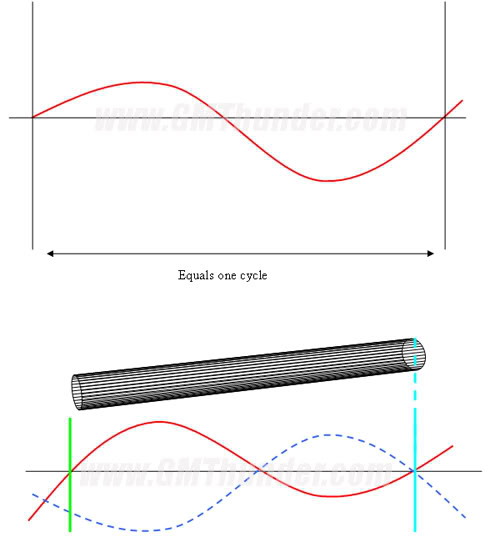
Think about your exhaust system. You are on the
DYNO and holding the engine at 2000 RPM.
The exhaust length is 65 inches and let's pretend
the pulse length is 65 inches.
In the diagram below you have a RED line which
indicates the pressure pulse as it EXITS the exhaust
port and travels the length of the exhaust pipe. When the pulse reaches the end of the pipe, it meets the atmosphere. When a moving object HITS another object there is a transfer of energy.
Think of a wave of WATER hitting a wall and bouncing
backward - air moves in a similar fashion. When the exhaust pulse hits the atmosphere it will reflect back toward the exhaust port. The dotted blue line represents this reflected wave - notice that the blue dotted line crosses the black line at, or below the axis.
This means the reflected pulse has reached the
exhaust port with LOWER PRESSURE.
Question One:
Will having a low pressure pulse reflect back
IMPROVE, or HURT the next exhaust pulse exiting?
Those who guessed that LOW PRESSURE will IMPROVE
the flow of the next pulse are CORRECT.
Here's why:
If you were water, or air exiting this exhaust pipe, would you find it easier to exit if there was a valley, or a hill?
The valley is the top scenario.
The hill is the bottom scenario.
Think of low pressure as a WEAK force. `Low` meaning
low force, or low resistance. When the exhaust valve is opening and the piston is pushing the waste out of the cylinder, the exiting pulse is HIGH pressure.
The exhaust gas will exit easier if there is little resistance
at the exhaust port. You can also think of low pressure as a VACUUM. It actually creates a sucking effect at the exhaust port so that when the valve opens, the low pressure area sucks the gas out of the cylinder.
Remember...fluids and gasses move from high pressure
to low pressure - that's a key point here.
So the reflected pulse is tuned to reach the port at LOW
pressure.
Now, what happens when you open your cut-out at 2000 RPM?
Have a look at the next diagram. Notice the top drawing has Engine RPM at 2000 RPM. The bottom has Engine RPM at 6000 RPM.
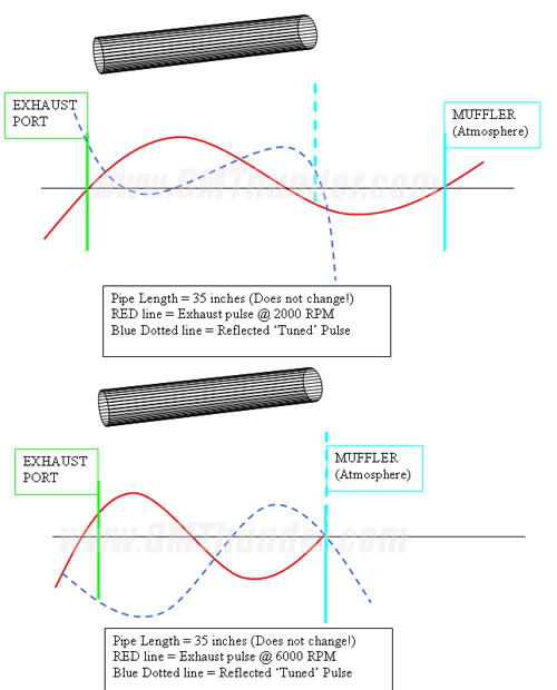
Think about what happens to the `EFFECTIVE LENGTH`
of your exhaust.
Things to think about:
Is the pipe tuned for a higher, or lower pulse now? The long RED wavelength is the exhaust pressure pulse @ 2000 RPM.
Question 3: At 6000 RPM with a shorter exhaust
pipe, (or cut-out open), will the torque be higher, or lower?
When you're talking about cutouts the distance is CRITICAL and will tune the exhaust to be efficient at ONE
RPM, with a tapering curve above and below that RPM. The RED wave in the top example extends beyond
the length of the pipe.
The WAVELENGTH/PRESSURE PULSE length at 2000 RPM
is LONGER than the TUNED LENGTH of the exhaust
pipe.
Now when you open the cut-out at 2000-3500 RPM
on the street, you notice a lack of POWER. People say "I lost BACKPRESSURE...That's Why I lost power!"
That is not true. By opening the cut out, you
have changed the tuning of the exhaust for the
RPM range you are using. Think about a pipe organ. Wonder why each note on the pipe organ has a DIFFERENT LENGTH of pipe?
"But why does the frequency of the exhaust decide how much power u make?"
It does not decide how much, but when the power
comes in. The pipe length in the exhaust has everything to do with how much power is made.
If you read up a few paragraphs you will see talk of
reflected pulses and exhaust pressure.
At 2000 RPM an exhaust pulse is 50 inches (for example). If we cut a pipe to be "resonant" at 2000 RPM, it would need to be 50 inches. This pipe would only be resonant at ONE RPM, and ONE frequency. The reflected pulse at 2000 RPM will reach the exhaust port and create a LOW PRESSURE area.
While the valves are opening and closing, the pulse
is reflecting back at 2000 RPM, everything is tuned
and resonant...which means it is highly efficient.
Someone driving around in the city would tune their
exhaust to this length because it would be more
efficient from 1000 to 3000 RPM with a PEAK at
around 2000 RPM (or somewhere in the middle).
When this guy goes racing, he opens his cut out. But today, he wants to open the cut out and drive around town. The pipe is now cut smaller in length. The tuned length is somewhere in the 5000 RPM range.
While he drives around at 2000 RPM, the exhaust
pressure pulses are still going to have a 50 inch
wavelength...but... The cut-out does not allow the reflected pulse to come back 180 degrees out of phase.
The reflected pulse returns at a higher pressure
at the port.
Check out this diagram:
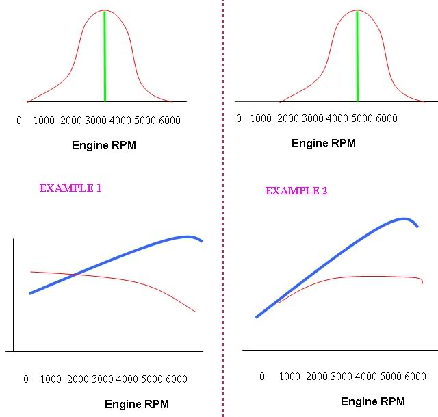
Notice the top section on the left and right side.
There is a hump with a green line highlighting the
highest point of the hump. Also notice the RPM
at where the peak of the hump occurs.
Directly below each is a simulated torque and horsepower graph. Which side represents a tuned exhaust for a SHORT PIPE, or CUT OUT?
Answer: Example two!
Just remember it's not BACKPRESSURE that is causing the torque loss, it's all about the tuning - you need to select a pipe length that provides the best power curve in a window of RPM that the car requires.
Just like above, if you're going to be racing,
place the cut-out in a spot that improves the
resonant RPM to around 5000 RPM (like the right
side). On a Thirdgen Camaro/Firebird this would be right around the catalytic converter area.
Then everything above and below 5000 RPM will
taper off within your shift window (4000-6000 RPM).
Continued....
Most of this information was gotten from Lukn4Trbl on fbody.com, including the drawings. The man knows way more than anyone should about exhaust.
I have edited alot of it for clarity, grammar and spelling as well as expanded on a few things that are more thirdgen specific and useful for the people in this forum. Read on!!!
More than you've ever wanted to know about backpressure...
Free Flowing Exhaust: Unrestricted flow means unrestricted power.
Cut-outs: Unrestricted flow, but tuned length has changed = power band shifts (depending on length and diameter of pipe). This causes the "loss of low end torque" feeling.
Those examples above are two different tuning methods, and WILL effect torque.
Let's talk about engine mechanics first.
We have a camshaft which is GEARED to the crankshaft. There are VALVE EVENTS which occur at specified
degrees in relation to the crank position.
If you look at a cam card, you will see notes like:
EVO, EVC, IVO, IVC (etc.)
EVO = Exhaust Valve Open
EVC = Exhast Valve Close
You need to understand that these points NEVER
change no matter how fast the engine spins. You also need to realize that the exhaust pipes and headers CAN NOT change length as engine RPM changes (obviously).
This means that your INTAKE and EXHAUST pipes are
TUNED for ONE specific RPM.
RPM changes which also changes the WAVELENGTH of
the PRESSURE PULSE.
Understand that an engine spinning at 1000 RPM
creates LESS pressure pulses than an engine spinning
at 6000 RPM.
Also understand at higher RPM these pulses must
happen FASTER in the same RELATIVE TIME (IE: PER MINUTE)
So...1000 pulses per minute have MORE TIME to happen than 6000 pulses per minute.
This means that higher RPM pulses have a SHORTER
wavelength (pulse length).
Anybody here with a basic understanding of audio
can relate short wavelength of high frequencies of a tweeter to long wavelength frequencies of bass tones of a sub woofer.
Think about your exhaust system. You are on the
DYNO and holding the engine at 2000 RPM.
The exhaust length is 65 inches and let's pretend
the pulse length is 65 inches.
In the diagram below you have a RED line which
indicates the pressure pulse as it EXITS the exhaust
port and travels the length of the exhaust pipe. When the pulse reaches the end of the pipe, it meets the atmosphere. When a moving object HITS another object there is a transfer of energy.
Think of a wave of WATER hitting a wall and bouncing
backward - air moves in a similar fashion. When the exhaust pulse hits the atmosphere it will reflect back toward the exhaust port. The dotted blue line represents this reflected wave - notice that the blue dotted line crosses the black line at, or below the axis.
This means the reflected pulse has reached the
exhaust port with LOWER PRESSURE.
Question One:
Will having a low pressure pulse reflect back
IMPROVE, or HURT the next exhaust pulse exiting?
Those who guessed that LOW PRESSURE will IMPROVE
the flow of the next pulse are CORRECT.
Here's why:
If you were water, or air exiting this exhaust pipe, would you find it easier to exit if there was a valley, or a hill?
The valley is the top scenario.
The hill is the bottom scenario.
Think of low pressure as a WEAK force. `Low` meaning
low force, or low resistance. When the exhaust valve is opening and the piston is pushing the waste out of the cylinder, the exiting pulse is HIGH pressure.
The exhaust gas will exit easier if there is little resistance
at the exhaust port. You can also think of low pressure as a VACUUM. It actually creates a sucking effect at the exhaust port so that when the valve opens, the low pressure area sucks the gas out of the cylinder.
Remember...fluids and gasses move from high pressure
to low pressure - that's a key point here.
So the reflected pulse is tuned to reach the port at LOW
pressure.
Now, what happens when you open your cut-out at 2000 RPM?
Have a look at the next diagram. Notice the top drawing has Engine RPM at 2000 RPM. The bottom has Engine RPM at 6000 RPM.
Think about what happens to the `EFFECTIVE LENGTH`
of your exhaust.
Things to think about:
Is the pipe tuned for a higher, or lower pulse now? The long RED wavelength is the exhaust pressure pulse @ 2000 RPM.
Question 3: At 6000 RPM with a shorter exhaust
pipe, (or cut-out open), will the torque be higher, or lower?
When you're talking about cutouts the distance is CRITICAL and will tune the exhaust to be efficient at ONE
RPM, with a tapering curve above and below that RPM. The RED wave in the top example extends beyond
the length of the pipe.
The WAVELENGTH/PRESSURE PULSE length at 2000 RPM
is LONGER than the TUNED LENGTH of the exhaust
pipe.
Now when you open the cut-out at 2000-3500 RPM
on the street, you notice a lack of POWER. People say "I lost BACKPRESSURE...That's Why I lost power!"
That is not true. By opening the cut out, you
have changed the tuning of the exhaust for the
RPM range you are using. Think about a pipe organ. Wonder why each note on the pipe organ has a DIFFERENT LENGTH of pipe?
"But why does the frequency of the exhaust decide how much power u make?"
It does not decide how much, but when the power
comes in. The pipe length in the exhaust has everything to do with how much power is made.
If you read up a few paragraphs you will see talk of
reflected pulses and exhaust pressure.
At 2000 RPM an exhaust pulse is 50 inches (for example). If we cut a pipe to be "resonant" at 2000 RPM, it would need to be 50 inches. This pipe would only be resonant at ONE RPM, and ONE frequency. The reflected pulse at 2000 RPM will reach the exhaust port and create a LOW PRESSURE area.
While the valves are opening and closing, the pulse
is reflecting back at 2000 RPM, everything is tuned
and resonant...which means it is highly efficient.
Someone driving around in the city would tune their
exhaust to this length because it would be more
efficient from 1000 to 3000 RPM with a PEAK at
around 2000 RPM (or somewhere in the middle).
When this guy goes racing, he opens his cut out. But today, he wants to open the cut out and drive around town. The pipe is now cut smaller in length. The tuned length is somewhere in the 5000 RPM range.
While he drives around at 2000 RPM, the exhaust
pressure pulses are still going to have a 50 inch
wavelength...but... The cut-out does not allow the reflected pulse to come back 180 degrees out of phase.
The reflected pulse returns at a higher pressure
at the port.
Check out this diagram:
Notice the top section on the left and right side.
There is a hump with a green line highlighting the
highest point of the hump. Also notice the RPM
at where the peak of the hump occurs.
Directly below each is a simulated torque and horsepower graph. Which side represents a tuned exhaust for a SHORT PIPE, or CUT OUT?
Answer: Example two!
Just remember it's not BACKPRESSURE that is causing the torque loss, it's all about the tuning - you need to select a pipe length that provides the best power curve in a window of RPM that the car requires.
Just like above, if you're going to be racing,
place the cut-out in a spot that improves the
resonant RPM to around 5000 RPM (like the right
side). On a Thirdgen Camaro/Firebird this would be right around the catalytic converter area.
Then everything above and below 5000 RPM will
taper off within your shift window (4000-6000 RPM).
Continued....
Last edited by urbanhunter44; 03-24-2006 at 10:15 AM.
 12-30-2005, 08:25 PM
#2
Supreme Member
Thread Starter
iTrader: (3)
Join Date: May 2004
Location: Brighton, CO
Posts: 4,345
Likes: 0
Received 1 Like
on
1 Post
Car: '72 Chevy Nova
Engine: Solid roller 355
Transmission: TH350
Axle/Gears: 8.5" 10-bolt 3.73 Posi
Here are a few questions so you can learn this a bit better. If you answer all of these correctly, you will
totally understand the difference between:
- Tuned length vs. Backpressure
- Restriction vs. Flow
- Velocity vs. Pressure
Quiz A
Using the diagram below, answer the 4 questions.
The RED line is POSITIVE PRESSURE (Initial Wave) and the
BLUE line is NEGATIVE PRESSURE (Reflected wave). Also note that this is very simple, it will be explained below.
The exhaust port is at the left side of the pipe.
#1. What is the pressure of the red line at the
exhaust port for Graph A?
#2. What is the pressure of the blue line at the
exhaust port for Graph B?
#3. What is the resulting pressure of both waves combined at the exhaust port for Graph A?
#4. What is the resulting pressure of both waves combined at the exhaust port for Graph B?
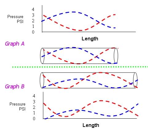
1. 3 psi
2. 0 psi
3. 5 psi
4. 3 psi
With some simple math above we can see that the
blue line is creating 2 PSI of negative pressure.
- 2 PSI (Graph A)
The Red line in Graph A is producing +3 PSI of exhaust pressure on the inital pulse. That means there is a difference of 5 PSI between both waves. The reflected pulse is leaving a negative zone at the port and literally sucking the exhaust out.
Since the initial wave is +3 PSI, it's going to
come out with higher velocity because of the 5 PSI
differential.
Graph B shows a similar scenario, but the reflected
wave comes back and hits the port at 0 PSI.
The intial exhaust pulse is 3 PSI.
Now there is a difference of 3 PSI.
Since the RED line is still higher pressure than
the reflected wave, the exhaust will move out
of the chamber, but not as quickly (velocity) and
therefore scavenging will be less.
You can now see that there is NO BACKPRESSURE,
but the power output will be less in Graph B.
We can also see that both pipes have no restriction,
and therefore cannot create backpressure on their own.
It is the tuned length that is causing a drop, or
increase in power.
LAST Diagram to PROVE there is no BACKPRESSURE in
a pipe:
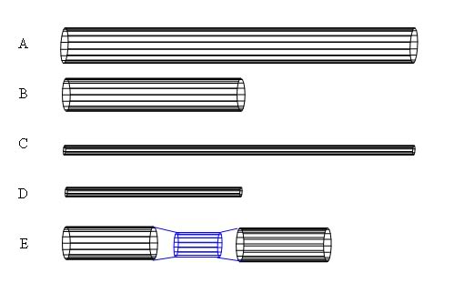
In the above picture:
Pipe A is 2.5" diameter x 20 inches long
Pipe B is 2.5" diameter x 10 inches long
Which statement is true
1. Pipe A will flow more exhaust because it is longer.
2. Pipe B will flow more exhaust because it is shorter
3. Both pipes will flow the same exhaust because
their diamter is the same.
The correct answer is 3.
Therefore, you can conclude there is no restriction
in open pipes of varying lengths.
I don't want to hear any more bull about backpressure bringing the world to an end, or it causing cancer. The term you are looking for is "tuned resonance"
when dealing with pressure pulses.
This is why the power band changes when the LENGTH
of pipe is changed, or a cut-out is opened.
"Why is it bad to put a 4" exhaust on my V6?"
The larger exhaust pipe would alter the velocity of the exhaust pulses, which would move them out of tune for a given exhaust length. Theoretically it would be possible to design an efficient 4" exhaust system for a V6, but it would only be efficient at a rediculous RPM due to the smaller amounts of exhaust being expelled and lower exhaust velocity.
Clues:
- The atmosphere has mass and can exert pressure.
- Volume of a pipe increases with diameter and length increase.
So what's the relation between Pipe DIAMETER and Engine Displacement?
I didn't want to get too detailed, but there are 1/8, 1/4, 1/2, 3/4 wavelengths that will enhance the exhaust system.
The trouble is, a secondary, or third harmonic is not as
powerful as the initial reflection, nor is the phase
of a sub-length wave. Excessive pipe diameters drop low RPM efficiency.
Tests show a loss in lower end power with an increase of pipe diameter. It's not always about the peak numbers, it's more to do with the average of the curve.
3" single is about the absolute minimum pipe
diameter for roughly 350 cubes peaking between
5500-6000 RPM.
4" single will do well with 400 cubes peaking
at 5500-6000 RPM.
2.25"-2.5" dual is about max for a 350 cube motor
peaking around 5500 RPM.
3" Dual is about maximum for a 350-400 cube motor
peaking between 6500-7000 RPM
With a larger pipe, there is more atmospheric pressure to overcome.
The pipe itself with the ENGINE OFF rests at atmospheric pressure. So...the more volume/capacity
the pipe has, the more work the exhaust pulses
have to perform to get out of the system.
Don't forget, the gasses are pulsing and moving
back and forth. Change in direction takes time,
and requires energy (inertia).
When you're dealing with exhaust gas which is less
dense than the air we breath, the exhaust has to
work very hard to get out of the pipe.
Getting the proper length and diameter is a big
deal when it comes to intake and exhaust tuning.
There are other variables which are going to come
into play.
"But what about my catalytic converter...or my
muffler?"
Which is more restrictive:
1. 3 inch inlet/3 inch outlet catalytic that flows 750 CFM @ 28 in./H20
2. 4 inch lnlet/4 inch outlet catalytic that
flows 600 CFM @ 28 in./H20
3. 2.5 inch pipe that flows 750 CFM @ 28 in./H20
The examples are exaggerated to show a point which
I believe is very important:
Restriction of a muffler, or catalytic can be overcome
in a smaller system and be more efficient than
a bigger pipe...as long as the flow is adequate.
Some tuners will go to a larger pipe while using
a somewhat "average" flowing catalytic/muffler.
They see a gain and attribute it to 'larger is better'
only because the surface area of the catalyic honey
comb has increased by 1" diameter allowing a touch
more flow than the 'average flowing' 3" unit.
Again, but investing in a high quality, high flowing
race muffler, or cat., the pipe size could have
remained the same with better results.
"As long as the cat/muffler flows the same cfm as the pipe, it would present no barrier, would it not?"
Not exactly. According to three sources:
David Vizard
John Morrison
National Dragster
A pulse hitting an object will be reflected.
In other words, the honeycomb center acts as the
reflective surface whether it flows well, or not.
This is the same principle as the pulse exiting the
pipe and hitting the atmosphere.
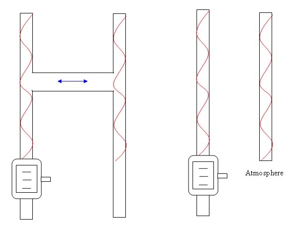
One last little blurb on crossovers.
As for H-pipe tuning and placement, I haven't been
able to find any conclusive write-ups to show
the correct tuning.
Here's a diagram of an H-pipe and two equal waves
per bank.
The pressure waves would normally be offset because
no two cylinder fire at the same time, but it will
help highlight the action of the H-pipe:
Well there's a quick overview of exhaust systems. If anyone has any questions I'll try to help you out the best I can. PM me or email me, or post them here.
totally understand the difference between:
- Tuned length vs. Backpressure
- Restriction vs. Flow
- Velocity vs. Pressure
Quiz A
Using the diagram below, answer the 4 questions.
The RED line is POSITIVE PRESSURE (Initial Wave) and the
BLUE line is NEGATIVE PRESSURE (Reflected wave). Also note that this is very simple, it will be explained below.
The exhaust port is at the left side of the pipe.
#1. What is the pressure of the red line at the
exhaust port for Graph A?
#2. What is the pressure of the blue line at the
exhaust port for Graph B?
#3. What is the resulting pressure of both waves combined at the exhaust port for Graph A?
#4. What is the resulting pressure of both waves combined at the exhaust port for Graph B?
1. 3 psi
2. 0 psi
3. 5 psi
4. 3 psi
With some simple math above we can see that the
blue line is creating 2 PSI of negative pressure.
- 2 PSI (Graph A)
The Red line in Graph A is producing +3 PSI of exhaust pressure on the inital pulse. That means there is a difference of 5 PSI between both waves. The reflected pulse is leaving a negative zone at the port and literally sucking the exhaust out.
Since the initial wave is +3 PSI, it's going to
come out with higher velocity because of the 5 PSI
differential.
Graph B shows a similar scenario, but the reflected
wave comes back and hits the port at 0 PSI.
The intial exhaust pulse is 3 PSI.
Now there is a difference of 3 PSI.
Since the RED line is still higher pressure than
the reflected wave, the exhaust will move out
of the chamber, but not as quickly (velocity) and
therefore scavenging will be less.
You can now see that there is NO BACKPRESSURE,
but the power output will be less in Graph B.
We can also see that both pipes have no restriction,
and therefore cannot create backpressure on their own.
It is the tuned length that is causing a drop, or
increase in power.
LAST Diagram to PROVE there is no BACKPRESSURE in
a pipe:
In the above picture:
Pipe A is 2.5" diameter x 20 inches long
Pipe B is 2.5" diameter x 10 inches long
Which statement is true
1. Pipe A will flow more exhaust because it is longer.
2. Pipe B will flow more exhaust because it is shorter
3. Both pipes will flow the same exhaust because
their diamter is the same.
The correct answer is 3.
Therefore, you can conclude there is no restriction
in open pipes of varying lengths.
I don't want to hear any more bull about backpressure bringing the world to an end, or it causing cancer. The term you are looking for is "tuned resonance"
when dealing with pressure pulses.
This is why the power band changes when the LENGTH
of pipe is changed, or a cut-out is opened.
"Why is it bad to put a 4" exhaust on my V6?"
The larger exhaust pipe would alter the velocity of the exhaust pulses, which would move them out of tune for a given exhaust length. Theoretically it would be possible to design an efficient 4" exhaust system for a V6, but it would only be efficient at a rediculous RPM due to the smaller amounts of exhaust being expelled and lower exhaust velocity.
Clues:
- The atmosphere has mass and can exert pressure.
- Volume of a pipe increases with diameter and length increase.
So what's the relation between Pipe DIAMETER and Engine Displacement?
I didn't want to get too detailed, but there are 1/8, 1/4, 1/2, 3/4 wavelengths that will enhance the exhaust system.
The trouble is, a secondary, or third harmonic is not as
powerful as the initial reflection, nor is the phase
of a sub-length wave. Excessive pipe diameters drop low RPM efficiency.
Tests show a loss in lower end power with an increase of pipe diameter. It's not always about the peak numbers, it's more to do with the average of the curve.
3" single is about the absolute minimum pipe
diameter for roughly 350 cubes peaking between
5500-6000 RPM.
4" single will do well with 400 cubes peaking
at 5500-6000 RPM.
2.25"-2.5" dual is about max for a 350 cube motor
peaking around 5500 RPM.
3" Dual is about maximum for a 350-400 cube motor
peaking between 6500-7000 RPM
With a larger pipe, there is more atmospheric pressure to overcome.
The pipe itself with the ENGINE OFF rests at atmospheric pressure. So...the more volume/capacity
the pipe has, the more work the exhaust pulses
have to perform to get out of the system.
Don't forget, the gasses are pulsing and moving
back and forth. Change in direction takes time,
and requires energy (inertia).
When you're dealing with exhaust gas which is less
dense than the air we breath, the exhaust has to
work very hard to get out of the pipe.
Getting the proper length and diameter is a big
deal when it comes to intake and exhaust tuning.
There are other variables which are going to come
into play.
"But what about my catalytic converter...or my
muffler?"
Which is more restrictive:
1. 3 inch inlet/3 inch outlet catalytic that flows 750 CFM @ 28 in./H20
2. 4 inch lnlet/4 inch outlet catalytic that
flows 600 CFM @ 28 in./H20
3. 2.5 inch pipe that flows 750 CFM @ 28 in./H20
The examples are exaggerated to show a point which
I believe is very important:
Restriction of a muffler, or catalytic can be overcome
in a smaller system and be more efficient than
a bigger pipe...as long as the flow is adequate.
Some tuners will go to a larger pipe while using
a somewhat "average" flowing catalytic/muffler.
They see a gain and attribute it to 'larger is better'
only because the surface area of the catalyic honey
comb has increased by 1" diameter allowing a touch
more flow than the 'average flowing' 3" unit.
Again, but investing in a high quality, high flowing
race muffler, or cat., the pipe size could have
remained the same with better results.
"As long as the cat/muffler flows the same cfm as the pipe, it would present no barrier, would it not?"
Not exactly. According to three sources:
David Vizard
John Morrison
National Dragster
A pulse hitting an object will be reflected.
In other words, the honeycomb center acts as the
reflective surface whether it flows well, or not.
This is the same principle as the pulse exiting the
pipe and hitting the atmosphere.
One last little blurb on crossovers.
As for H-pipe tuning and placement, I haven't been
able to find any conclusive write-ups to show
the correct tuning.
Here's a diagram of an H-pipe and two equal waves
per bank.
The pressure waves would normally be offset because
no two cylinder fire at the same time, but it will
help highlight the action of the H-pipe:
Well there's a quick overview of exhaust systems. If anyone has any questions I'll try to help you out the best I can. PM me or email me, or post them here.
Last edited by urbanhunter44; 12-30-2005 at 09:03 PM.


Trending Topics
 12-31-2005, 01:07 AM
#9
Supreme Member
Thread Starter
iTrader: (3)
Join Date: May 2004
Location: Brighton, CO
Posts: 4,345
Likes: 0
Received 1 Like
on
1 Post
Car: '72 Chevy Nova
Engine: Solid roller 355
Transmission: TH350
Axle/Gears: 8.5" 10-bolt 3.73 Posi
Yeah, this will probably only appeal to people who are really really into their exhaust systems
It would be cool if the mods would sticky this, I'm sure these questions will come up again and again.
It would be cool if the mods would sticky this, I'm sure these questions will come up again and again.
12-31-2005, 01:56 AM
#10
Supreme Member

Join Date: Oct 2001
Location: NWOhioToledoArea
Posts: 8,113
Likes: 0
Received 5 Likes
on
5 Posts
Car: 86-FireBird
Engine: -MPFI
Transmission: T5
Axle/Gears: 3:42
There is some great info here too:
"You can build a quiet exhaust system that performs almost like open headers."
By Jim Hand & Tom Hand
http://www.pontiacstreetperformance....p/exhaust.html
"You can build a quiet exhaust system that performs almost like open headers."
By Jim Hand & Tom Hand
http://www.pontiacstreetperformance....p/exhaust.html
 12-31-2005, 04:41 PM
#12
Senior Member

Join Date: Oct 2003
Location: LaGrange (10min from Poughkeepsie), NY
Posts: 942
Likes: 0
Received 0 Likes
on
0 Posts
Car: 1992 Camaro RS - not real slow anymore...
Engine: SPDC 360 MAF EFI /w a Holley Stealth Ram
Transmission: T5 untill it blows up from to much torque
Axle/Gears: Ford 9" /w auburn pro & 3.89's
Ouch, my head... So, those graphs on the bottom are basically cosine waves?


 01-01-2006, 05:27 PM
#16
Senior Member
Join Date: Aug 2005
Location: San Leandro(Oakland)
Posts: 618
Likes: 0
Received 0 Likes
on
0 Posts
Car: '92 Toyota Pickup
Engine: 22R-E
Transmission: 5sp Manual
Axle/Gears: 4:??
Very nice layout of the info, kinda like an online course.
Great job dude, and yes this should be a sticky.
Great job dude, and yes this should be a sticky.
01-01-2006, 05:47 PM
#17
Senior Member
Join Date: Oct 2005
Location: Cincinnati, Ohio
Posts: 535
Likes: 0
Received 1 Like
on
1 Post
Car: 1989 Iroc Z
Engine: 496 BBC
Transmission: th400
Axle/Gears: 4.11
Can you write conclusions? So my High Flow CAT and my 3" cat-back, flowmaster 80 series muffer, and it comes out to 2.5" and 3" tips.. Is this helping me or hurting me? Am i losing low end torque?
Last edited by M1tch; 01-01-2006 at 05:49 PM.
01-01-2006, 10:47 PM
#18
Supreme Member
Thread Starter
iTrader: (3)
Join Date: May 2004
Location: Brighton, CO
Posts: 4,345
Likes: 0
Received 1 Like
on
1 Post
Car: '72 Chevy Nova
Engine: Solid roller 355
Transmission: TH350
Axle/Gears: 8.5" 10-bolt 3.73 Posi
Originally posted by M1tch
Can you write conclusions? So my High Flow CAT and my 3" cat-back, flowmaster 80 series muffer, and it comes out to 2.5" and 3" tips.. Is this helping me or hurting me? Am i losing low end torque?
Can you write conclusions? So my High Flow CAT and my 3" cat-back, flowmaster 80 series muffer, and it comes out to 2.5" and 3" tips.. Is this helping me or hurting me? Am i losing low end torque?
06-03-2006, 04:27 PM
#20
Junior Member
Join Date: May 2005
Location: Provo, UT
Posts: 47
Likes: 0
Received 0 Likes
on
0 Posts
Car: 1989 Camaro RS
Engine: 355
Transmission: T-10
Axle/Gears: Moser 12 bolt/3.73
Hey urbanhunter,
I have a 355 (redline=6500) with SLP shorty headers. I am getting ready to do an exhaust system and would like your advice. I am thinking about either a 3" oval-tubed dual with an "X-pipe", or a 3" oval-tubed single with a "Y-pipe". Both of these will exit right in front of the rear tires, so they wont be quite as long as normal (exiting out the rear). I am doing the oval-tubing because of ground clearance issues (subframe connectors). I have to exit before the rear tires because of subframe connectors and 3-link suspension. What is your recomendation?
THANKS!!!
06-03-2006, 05:17 PM
#21
Supreme Member
Join Date: Sep 2005
Location: Osceola Indiana
Posts: 2,151
Likes: 0
Received 0 Likes
on
0 Posts
Car: 92 RS(sold) 1989 IROC-Z
Engine: 350 TPI
Transmission: 700R4
Axle/Gears: ones that turn
sweet write up lots of great information, this should definently be a sticky
06-03-2006, 11:14 PM
#22
Supreme Member
Thread Starter
iTrader: (3)
Join Date: May 2004
Location: Brighton, CO
Posts: 4,345
Likes: 0
Received 1 Like
on
1 Post
Car: '72 Chevy Nova
Engine: Solid roller 355
Transmission: TH350
Axle/Gears: 8.5" 10-bolt 3.73 Posi
Originally Posted by Can_of_yum_yum
Hey urbanhunter,
I have a 355 (redline=6500) with SLP shorty headers. I am getting ready to do an exhaust system and would like your advice. I am thinking about either a 3" oval-tubed dual with an "X-pipe", or a 3" oval-tubed single with a "Y-pipe". Both of these will exit right in front of the rear tires, so they wont be quite as long as normal (exiting out the rear). I am doing the oval-tubing because of ground clearance issues (subframe connectors). I have to exit before the rear tires because of subframe connectors and 3-link suspension. What is your recomendation?
THANKS!!!
I have a 355 (redline=6500) with SLP shorty headers. I am getting ready to do an exhaust system and would like your advice. I am thinking about either a 3" oval-tubed dual with an "X-pipe", or a 3" oval-tubed single with a "Y-pipe". Both of these will exit right in front of the rear tires, so they wont be quite as long as normal (exiting out the rear). I am doing the oval-tubing because of ground clearance issues (subframe connectors). I have to exit before the rear tires because of subframe connectors and 3-link suspension. What is your recomendation?
THANKS!!!
As for crossover pipes, an X will make more power but has an annoying harmonic reasonance recognized as a low humming, an H doesn't and sounds better but has slightly less power. If this is track only/weekend warrior, the reasonance won't bother you. If you do use an H pipe, the H should be slightly larger than the other tubing. In this case, 3.25" or 3.5".
I'd also recommend Long Tube Headers (hooker makes some nice ones) with at least a 1 7/8" primary with 3" collectors. You'd see a good power gain (if you're at least in the 350 hp area).
Last edited by urbanhunter44; 06-03-2006 at 11:19 PM.
08-23-2006, 10:15 PM
#23
Member
iTrader: (6)
Join Date: Jul 2004
Location: RogueValley, Oregon
Posts: 405
Likes: 0
Received 0 Likes
on
0 Posts
Car: 84Z & Porsche
Engine: 427sbc - 471 - 850 Demon Claw
Transmission: Bowtie stage II TH700R4 - 10" 3000
Axle/Gears: 9 Bolt w/ 3:45's
Hello all, Hello urbanhunter44,
I have a built SBC of 427 ci. With this I have SLP 1 3/4 primaries & 3" collectors (Shorty headers) & 3" SLP wye pipe. The intermediate pipe is 3" back to the SLP 3" in , and dual 2 1/2 out. I have a cut out where the CAT used to be. Now I'm understanding that I need a 4" system to be better with my 427 @ 7k rpm, or true dual 3" system with an x pipe mid stream. Does all of the above make sense???
Any advice appreciated, and thanks for your post/sticky here (I also vote for sticky).
ED
(AKA: Cocacolakidd)
Last edited by cocacolakidd; 08-23-2006 at 10:19 PM.
08-24-2006, 08:17 PM
#25
Supreme Member
Thread Starter
iTrader: (3)
Join Date: May 2004
Location: Brighton, CO
Posts: 4,345
Likes: 0
Received 1 Like
on
1 Post
Car: '72 Chevy Nova
Engine: Solid roller 355
Transmission: TH350
Axle/Gears: 8.5" 10-bolt 3.73 Posi
Assuming you're making 450+ hp, I'd go with a dual 3" X-piped system, dumped with a couple of bullet mufflers. What's your exact setup?
And like 1989GTA said, step up to some better breathing headers if you have the cash for it. 1 3/4" will work, but stepping up to a 1 7/8 set will help on the top end. What are your quarter mile times?
And like 1989GTA said, step up to some better breathing headers if you have the cash for it. 1 3/4" will work, but stepping up to a 1 7/8 set will help on the top end. What are your quarter mile times?
08-24-2006, 09:44 PM
#26
Member
iTrader: (6)
Join Date: Jul 2004
Location: RogueValley, Oregon
Posts: 405
Likes: 0
Received 0 Likes
on
0 Posts
Car: 84Z & Porsche
Engine: 427sbc - 471 - 850 Demon Claw
Transmission: Bowtie stage II TH700R4 - 10" 3000
Axle/Gears: 9 Bolt w/ 3:45's
Hello urbanhunter44,
As of now I have SLP stainless steel from 1 3/4 headers all the way back with 3" piping, open exhaust while racing with cut-out where the cat was - Engine is a 427 ci Small block set up for road race, with a 471 supercharger, Barry Grant 850, all forged internals, Comp 288hr roller cam, Pro Top Line heads worked over well. I have never had it on a drag strip track. So far it does pretty good up in the 160mph range on a open circuit track, but I think it could be better. So I am assuming after this season I will pull it down and install 1 7/8" primary headers and dual 3" with X, sometime this coming winter. I would then also have dual cutouts in the new system.
Any and all information/help appreciated for this amateur racer...
Ed.
08-25-2006, 06:50 PM
#27
Member
iTrader: (6)
Join Date: Jul 2004
Location: RogueValley, Oregon
Posts: 405
Likes: 0
Received 0 Likes
on
0 Posts
Car: 84Z & Porsche
Engine: 427sbc - 471 - 850 Demon Claw
Transmission: Bowtie stage II TH700R4 - 10" 3000
Axle/Gears: 9 Bolt w/ 3:45's
Hello all,
Another question here. What ever happened to tuned exhaust headers? Where the length of each primary pipe coming off the head is tuned to equal length to all others before going into the collector, and the headers are tuned to the exhaust pulse also.
I was just wondering if these type of headers were that much better, or just that much more costly? I know I have spent a bunch to have every thing on this motor blueprinted ++ (Oil pump to oil passages, and every thing in between), and therefore I was wondering if tuned headers were truly that much better.
Thanx, Ed.
08-25-2006, 08:40 PM
#28
Supreme Member
Thread Starter
iTrader: (3)
Join Date: May 2004
Location: Brighton, CO
Posts: 4,345
Likes: 0
Received 1 Like
on
1 Post
Car: '72 Chevy Nova
Engine: Solid roller 355
Transmission: TH350
Axle/Gears: 8.5" 10-bolt 3.73 Posi
How much boost are you running?
At your power level, yes, tuned headers would be worth it if you want to spend the money. They're usually referred to as "equal length" headers by manufacturers. Also consider going with equal length stepped headers. Those start getting pricey.
A roadracing/circle track motor is revving high, and your cam/heads are definetly all top end beasts. Going to larger primary headers and those true duals will help alot on the top end, to let her REALLY breathe. Equal length stepped headers may be something you want to research into and see if you want to go that route. It is quite expensive to get a set of stepped headers, but if you're serious about racing it's worth it.
08-25-2006, 09:18 PM
#29
Member
iTrader: (6)
Join Date: Jul 2004
Location: RogueValley, Oregon
Posts: 405
Likes: 0
Received 0 Likes
on
0 Posts
Car: 84Z & Porsche
Engine: 427sbc - 471 - 850 Demon Claw
Transmission: Bowtie stage II TH700R4 - 10" 3000
Axle/Gears: 9 Bolt w/ 3:45's
Thanks for the info on the equal length stepped headers. I am definately going to start the search for a set that will fit a third gen, and my oversize oil pan (Canton-roadrace). That pan has been a pain all along to fit any exhaust around it, but where there is a will there is a way.
Ed (Aka:cocacolakidd)
Ed (Aka:cocacolakidd)
09-08-2006, 12:59 PM
#30
TGO Supporter/Moderator
iTrader: (12)
Join Date: Jul 1999
Location: SALEM, NH
Posts: 11,730
Likes: 0
Received 89 Likes
on
75 Posts
Car: '88 Formula, '94 Corvette, '95 Bird
Engine: LC9, 355" LT1, LT1
Transmission: T5, Zf6, 4L60E
Axle/Gears: 3.42, Dana44 3.45, 3.23
Exhausting tuning is true.
Prime example. On my jetski, the band clamp broke on the exhaust, causing it to leak out the top of the pipe, rather than travel the whole organization of pipes and weird shaped cones.
The thing wouldn't even MOVE. it bogged, stalled, wouldn't even putt back to shore.
- Joe
Prime example. On my jetski, the band clamp broke on the exhaust, causing it to leak out the top of the pipe, rather than travel the whole organization of pipes and weird shaped cones.
The thing wouldn't even MOVE. it bogged, stalled, wouldn't even putt back to shore.
- Joe
 11-09-2006, 09:42 AM
#32
Member
Join Date: Jun 2006
Location: SW Iowa
Posts: 227
Likes: 0
Received 1 Like
on
1 Post
Car: '88 Formula
Engine: 406, CF heads, Comp 212/218, Rhoads
Transmission: WC T5, 0.61 option
Axle/Gears: 10-bolt 3.08, re-ground Auburn Posi
Some more on exhaust...
A very good post, with great info. You can't know too much about exhaust, if you're serious about performance.
If I may, I'd like to add to the info. All of this follows from your post, and fits a lot of experience.
Headers
Crossovers are most effective for V8 engines. This is because of a V8's unbalanced exhaust pulse timing. Here's a simple picture, of a Chevy V8 turning 6 revolutions.
...Left bank: |..|.||.|..|.||.|..|.||.
Firing order: 184365721843657218436572
..Right bank: .||.|..|.||.|..|.||.|..|
The vertical bars indicate when a bank has a firing cylinder. This very clearly shows that as the engine runs, the left manifold (or collector) sees two exhaust pulses in rapid succession when cylinders 5 and 7 fire. Same for the right when 8 and 4 fire. So when 5/7 fire, the left side has an extra-wide pressure wave and the right side has a low pressure area. When 8/4 fire, the left side has the low pressure area and the right side gets the extra-wide pulse. This tends to mess up the tuning for those cylinders.
FOR A V8--
Crossovers can also help other "V" or "H" engines (V6, V10, H6), but only by balancing exhaust flow between the cylinder banks. In these engines, an "X" is by far more effective than an "H."
Where do you position the crossover?
Generally, as close to the manifold or collector outlets as possible. Here's a simpe way to be sure you don't get it too far back:
If I may, I'd like to add to the info. All of this follows from your post, and fits a lot of experience.
Headers
- Small-diameter tubes aid low-end torque.
- Short tubes aid low-end torque.
- Large-diameter tubes aid high-end power.
- Long tubes aid high-end power.
- Equal-length tubes make a higher power peak, in a narrower RPM band. This is because all cylinders get tuned for the same RPM range. Generally better for racing applications.
- Unequal-length tubes make a lower power peak across a wider RPM band. This is because each cylinder gets tuned for a different RPM range. Generally better for street applications.
- Headers get most of their tuning from the lengths of the tubes, and less from the total length of the exhaust system. This is because the header collector and reducer make up a larger volume of greater air mass where the pulses reflect back, long before they get to the end of the tail pipe.
Crossovers are most effective for V8 engines. This is because of a V8's unbalanced exhaust pulse timing. Here's a simple picture, of a Chevy V8 turning 6 revolutions.
...Left bank: |..|.||.|..|.||.|..|.||.
Firing order: 184365721843657218436572
..Right bank: .||.|..|.||.|..|.||.|..|
The vertical bars indicate when a bank has a firing cylinder. This very clearly shows that as the engine runs, the left manifold (or collector) sees two exhaust pulses in rapid succession when cylinders 5 and 7 fire. Same for the right when 8 and 4 fire. So when 5/7 fire, the left side has an extra-wide pressure wave and the right side has a low pressure area. When 8/4 fire, the left side has the low pressure area and the right side gets the extra-wide pulse. This tends to mess up the tuning for those cylinders.
FOR A V8--
- It is not possible to adjust the firing order to prevent this in a V8. No other engine type has this issue.
- A crossover on a V8 helps to equalize these extra-wide pulses and low pressure areas, and helps the tuning for both banks.
- Well-designed unequal-length headers can reduce this effect, and make it disappear altogether in a narrow RPM band, without a crossover.
- Equal-length headers ALWAYS benefit from a crossover.
- The shorter the crossover is, the more effective it is.
- An "X" crossover gives the ultimate in balance, but causes all 8 cylinders to exit through both tailpipes.
- Some exhaust makers (like Flowmaster) make an "H" crossover that is of zero length. The two pipes run parallel to each other, with no more than a welded hole between them at one point. This is done to get the maximum balance, while minimizing the actual crossover of exhaust flow between pipes.
- I can't way whether a "zero-length" "H" is better than an "X." Flowmaster must think it matters. Or maybe it just gives them the sound they want. All I can say for sure is that the shorter the crossover is, the better.
Crossovers can also help other "V" or "H" engines (V6, V10, H6), but only by balancing exhaust flow between the cylinder banks. In these engines, an "X" is by far more effective than an "H."
Where do you position the crossover?
Generally, as close to the manifold or collector outlets as possible. Here's a simpe way to be sure you don't get it too far back:
- Paint a line lengthwise down the pipes from the manifold/collector outlets for 5 or 6 feet. Use a non-heat resistant paint.
- Let the paint dry, then go for a few runs.
- Examine the paint. The crossover must be installed within the area where the paint is definitely burned. And, the closer to the manifold/collector outlets, the better.
Last edited by SR-71; 11-09-2006 at 10:11 AM.
11-09-2006, 09:51 AM
#33
Member
Join Date: Jun 2006
Location: SW Iowa
Posts: 227
Likes: 0
Received 1 Like
on
1 Post
Car: '88 Formula
Engine: 406, CF heads, Comp 212/218, Rhoads
Transmission: WC T5, 0.61 option
Axle/Gears: 10-bolt 3.08, re-ground Auburn Posi
No. The exhaust pulses just see the beginning of the progression as the opening. There is no difference between this and if the pipe was cut square where the progression begins.
11-09-2006, 10:19 AM
#34
Member
Join Date: Jun 2006
Location: SW Iowa
Posts: 227
Likes: 0
Received 1 Like
on
1 Post
Car: '88 Formula
Engine: 406, CF heads, Comp 212/218, Rhoads
Transmission: WC T5, 0.61 option
Axle/Gears: 10-bolt 3.08, re-ground Auburn Posi
Exhausting tuning is true.
Prime example. On my jetski, the band clamp broke on the exhaust, causing it to leak out the top of the pipe, rather than travel the whole organization of pipes and weird shaped cones.
The thing wouldn't even MOVE. it bogged, stalled, wouldn't even putt back to shore.
- Joe
Prime example. On my jetski, the band clamp broke on the exhaust, causing it to leak out the top of the pipe, rather than travel the whole organization of pipes and weird shaped cones.
The thing wouldn't even MOVE. it bogged, stalled, wouldn't even putt back to shore.
- Joe
As you experienced, exhaust tuning is particularly important on a 2-stroke engine. Since a 2-stroke has no valves, the exhaust pressure pulses have a dramatic affect on the cylinder's exhaust/refill process.
2-stroke exhaust systems are designed to amplify the pulses and time their return to the exhaust port very carefully. (Thus 2-strokes don't have mufflers. They're call "expansion chambers.") Otherwise, you get what you experienced. When your clamp let go, the exhaust scavenging effect was so pronounced (with little or no returning pressure pulses) that the intake charge was being sucked out of the exhaust port, causing very low compression in the cylinders.
11-09-2006, 07:10 PM
#35
Member
iTrader: (6)
Join Date: Jul 2004
Location: RogueValley, Oregon
Posts: 405
Likes: 0
Received 0 Likes
on
0 Posts
Car: 84Z & Porsche
Engine: 427sbc - 471 - 850 Demon Claw
Transmission: Bowtie stage II TH700R4 - 10" 3000
Axle/Gears: 9 Bolt w/ 3:45's
Wow, lots of great info here...
After seeing allot of those electric superchargers advertised on eBay, and other places. I'm wondering if one was to attach one, or even two in tandem, on the exhaust as a scavenger if this would help the exhaust. With two of these maybe I could get away with a 3" system instead of a 4" system. Yeah I know those cheep electric superchargers are plastic, and would probably melt. So if one could get a chrome alloy, or inkcanell alloy they would hold up to the heat. Has any one ever tried thistype of scavenging??
Thanks, ~Ed~
11-10-2006, 07:56 PM
#36
So is there any benefit to putting an H-Pipe on a 3rd Gen exhaust following the factory routing pattern and with dual cats? Just wondering as the passenger side exhaust H-Pipe would be close to the header but the drivers side exhaust would be much further away as it snakes it way over to the passenger side under the front of the oil pan. So the pipes would not be equal distant at the H-Pipe connection.
I will soon be upgrading my exhaust one more time and it would be a good time to install an H-Pipe if there is any benefit. Thanks Guys.
I will soon be upgrading my exhaust one more time and it would be a good time to install an H-Pipe if there is any benefit. Thanks Guys.
11-14-2006, 01:51 AM
#37
Supreme Member
Thread Starter
iTrader: (3)
Join Date: May 2004
Location: Brighton, CO
Posts: 4,345
Likes: 0
Received 1 Like
on
1 Post
Car: '72 Chevy Nova
Engine: Solid roller 355
Transmission: TH350
Axle/Gears: 8.5" 10-bolt 3.73 Posi
Wow, lots of great info here...
After seeing allot of those electric superchargers advertised on eBay, and other places. I'm wondering if one was to attach one, or even two in tandem, on the exhaust as a scavenger if this would help the exhaust. With two of these maybe I could get away with a 3" system instead of a 4" system. Yeah I know those cheep electric superchargers are plastic, and would probably melt. So if one could get a chrome alloy, or inkcanell alloy they would hold up to the heat. Has any one ever tried thistype of scavenging??
Thanks, ~Ed~
After seeing allot of those electric superchargers advertised on eBay, and other places. I'm wondering if one was to attach one, or even two in tandem, on the exhaust as a scavenger if this would help the exhaust. With two of these maybe I could get away with a 3" system instead of a 4" system. Yeah I know those cheep electric superchargers are plastic, and would probably melt. So if one could get a chrome alloy, or inkcanell alloy they would hold up to the heat. Has any one ever tried thistype of scavenging??
Thanks, ~Ed~
Originally Posted by 1989GTATransAm
So is there any benefit to putting an H-Pipe on a 3rd Gen exhaust following the factory routing pattern and with dual cats? Just wondering as the passenger side exhaust H-Pipe would be close to the header but the drivers side exhaust would be much further away as it snakes it way over to the passenger side under the front of the oil pan. So the pipes would not be equal distant at the H-Pipe connection.
I will soon be upgrading my exhaust one more time and it would be a good time to install an H-Pipe if there is any benefit. Thanks Guys.
I will soon be upgrading my exhaust one more time and it would be a good time to install an H-Pipe if there is any benefit. Thanks Guys.
11-15-2006, 12:36 PM
#39
Supreme Member
Thread Starter
iTrader: (3)
Join Date: May 2004
Location: Brighton, CO
Posts: 4,345
Likes: 0
Received 1 Like
on
1 Post
Car: '72 Chevy Nova
Engine: Solid roller 355
Transmission: TH350
Axle/Gears: 8.5" 10-bolt 3.73 Posi
Tuned length is a big issue when tuning your car to run it's best!
11-15-2006, 10:43 PM
#40
Junior Member

Join Date: Nov 2006
Posts: 31
Likes: 0
Received 0 Likes
on
0 Posts
let me rephrase do i need to tune length after an X pipe. because, the X does about the same thing a tuned length set up does????right????? i am also running a full length exhaust out the rear of the car. its a set up i made from oval tubes an X pipe and boom tubes by dr gas. its close to a NASCAR type exhaust. dr gas claims 500 RPM increase of usable power on both ends of the power band with the X pipe!?!? so what do you think. im just a broke down tool maker/fabricator. by the way you could NOT pay me to fool with that oval tube @#$%$#@#$$ again AMEN.
11-16-2006, 02:22 AM
#41
Supreme Member
Thread Starter
iTrader: (3)
Join Date: May 2004
Location: Brighton, CO
Posts: 4,345
Likes: 0
Received 1 Like
on
1 Post
Car: '72 Chevy Nova
Engine: Solid roller 355
Transmission: TH350
Axle/Gears: 8.5" 10-bolt 3.73 Posi
let me rephrase do i need to tune length after an X pipe. because, the X does about the same thing a tuned length set up does????right????? i am also running a full length exhaust out the rear of the car. its a set up i made from oval tubes an X pipe and boom tubes by dr gas. its close to a NASCAR type exhaust. dr gas claims 500 RPM increase of usable power on both ends of the power band with the X pipe!?!? so what do you think. im just a broke down tool maker/fabricator. by the way you could NOT pay me to fool with that oval tube @#$%$#@#$$ again AMEN.
The term "tuned length" simply refers to the effective length of your exhaust (tuned via actual length or with "backpressure"). The only way to know for sure what YOUR car wants to run it's best is to set up the exhaust and work from there. For a street/strip car that has a lot of power I'd suggest a simple 3" dual setup with an x-pipe, dumping at the rear. The tuned length would be relatively short providing you use good flowing mufflers.
A shorter tuned length (essentially less resistance/backpressure) will move the usable RPM band up to where a high-revving (big duration cammed) motor will need to be.
What's your full motor/exhaust/tranny/rear end gear setup and I'll try to give you some more specific info.
11-16-2006, 12:28 PM
#42
Junior Member
Join Date: Nov 2006
Posts: 31
Likes: 0
Received 0 Likes
on
0 Posts
Ok, i have 1995 LT1 383, hand ported heads, 11.0:1 compresion. comp cams XFI 242/248 @ 0.50" 584/579 lift.hooker super comp headers. blue printed and balanced.--- fuel system upgrades, electric water pump, cloyes double roller timing set (that timing setup is the trick for LT1/4) and other tid bits.
exhaust is oval and round 3" dual, oval X and boom tubes that exit out the rear of the car.all of this stuf came from Dr gas it is the same stuff used by NASCAR.
tranny is 4L60E with a TCI kit and a 2800-3200 stall. the trans shifts @ 6500 rpms.
for the rear 3.73 gears spinning 245/50/16 tires.
the car is a 1985 berlinetta that is about 800 lbs lighter than stock.
thanks for the help. let me know if you need more info
11-25-2006, 03:53 PM
#43
Supreme Member
Thread Starter
iTrader: (3)
Join Date: May 2004
Location: Brighton, CO
Posts: 4,345
Likes: 0
Received 1 Like
on
1 Post
Car: '72 Chevy Nova
Engine: Solid roller 355
Transmission: TH350
Axle/Gears: 8.5" 10-bolt 3.73 Posi
Ok, i have 1995 LT1 383, hand ported heads, 11.0:1 compresion. comp cams XFI 242/248 @ 0.50" 584/579 lift.hooker super comp headers. blue printed and balanced.--- fuel system upgrades, electric water pump, cloyes double roller timing set (that timing setup is the trick for LT1/4) and other tid bits.
exhaust is oval and round 3" dual, oval X and boom tubes that exit out the rear of the car.all of this stuf came from Dr gas it is the same stuff used by NASCAR.
tranny is 4L60E with a TCI kit and a 2800-3200 stall. the trans shifts @ 6500 rpms.
for the rear 3.73 gears spinning 245/50/16 tires.
the car is a 1985 berlinetta that is about 800 lbs lighter than stock.
thanks for the help. let me know if you need more info
exhaust is oval and round 3" dual, oval X and boom tubes that exit out the rear of the car.all of this stuf came from Dr gas it is the same stuff used by NASCAR.
tranny is 4L60E with a TCI kit and a 2800-3200 stall. the trans shifts @ 6500 rpms.
for the rear 3.73 gears spinning 245/50/16 tires.
the car is a 1985 berlinetta that is about 800 lbs lighter than stock.
thanks for the help. let me know if you need more info
For that car I'd go with nothing less than long tubes, 3" dual exhaust, X-piped, assuming you want to keep the mufflers.
 11-28-2006, 11:24 AM
#44
Member
Join Date: Nov 2002
Location: Maryville, TN
Posts: 211
Likes: 0
Received 1 Like
on
1 Post
Car: 1987 IROC Z/28
Engine: 5.0L TPI. Custom Tune
Transmission: 5 Speed/ Pro5.0 short /hurst stick
Axle/Gears: 1LE 10 bolt Rear/T2R 3.45 PBR/disc
Urban Hunter you are obviously the answer man when it comes to exhaust systems and I appreciate you helping us all out.
I have a LB9 TPI HO engine in my 87 IROC. It is a dedicated track (road racing and autocross) car and I need lots of torque and 2nd / 3rd gear HP. Currently stock (minus the A.I.R) -- and I'm looking to do something in the off season.
Should I try some used headman's with a Y pipe and get a dyno-tune before investing huge money? I was looking at these
https://www.thirdgen.org/forums/atta...y-101_0334.jpg
from a board member..
thoughts?
EDIT: I forgot to mention, i've made the dual ram air "velocity stack" mod and am running K&Ns to force air in, i just need to let it out and dumping the stock exhaust is a good start. (i think)
Last edited by BrianChevy; 11-28-2006 at 11:32 AM.
11-29-2006, 03:59 AM
#45
Supreme Member
Thread Starter
iTrader: (3)
Join Date: May 2004
Location: Brighton, CO
Posts: 4,345
Likes: 0
Received 1 Like
on
1 Post
Car: '72 Chevy Nova
Engine: Solid roller 355
Transmission: TH350
Axle/Gears: 8.5" 10-bolt 3.73 Posi
Urban Hunter you are obviously the answer man when it comes to exhaust systems and I appreciate you helping us all out.
I have a LB9 TPI HO engine in my 87 IROC. It is a dedicated track (road racing and autocross) car and I need lots of torque and 2nd / 3rd gear HP. Currently stock (minus the A.I.R) -- and I'm looking to do something in the off season.
Should I try some used headman's with a Y pipe and get a dyno-tune before investing huge money? I was looking at these
https://www.thirdgen.org/forums/atta...y-101_0334.jpg
from a board member..
thoughts?
EDIT: I forgot to mention, i've made the dual ram air "velocity stack" mod and am running K&Ns to force air in, i just need to let it out and dumping the stock exhaust is a good start. (i think)
I have a LB9 TPI HO engine in my 87 IROC. It is a dedicated track (road racing and autocross) car and I need lots of torque and 2nd / 3rd gear HP. Currently stock (minus the A.I.R) -- and I'm looking to do something in the off season.
Should I try some used headman's with a Y pipe and get a dyno-tune before investing huge money? I was looking at these
https://www.thirdgen.org/forums/atta...y-101_0334.jpg
from a board member..
thoughts?
EDIT: I forgot to mention, i've made the dual ram air "velocity stack" mod and am running K&Ns to force air in, i just need to let it out and dumping the stock exhaust is a good start. (i think)
Running without mufflers and "less backpressure" (shorter tuned length) you're going to drive your RPM band up. Tricky with TPI cars because they don't like to rev out.
I'd suggest headers, no cats, 3" pipe all the way back with a decent muffler. It'll keep your tuned length long enough that the exhaust will help you make torque and hp down where your TPI can breathe, but it'll open up the exhaust enough to give you a bunch more power.
11-29-2006, 08:39 AM
#46
Member
Join Date: Nov 2002
Location: Maryville, TN
Posts: 211
Likes: 0
Received 1 Like
on
1 Post
Car: 1987 IROC Z/28
Engine: 5.0L TPI. Custom Tune
Transmission: 5 Speed/ Pro5.0 short /hurst stick
Axle/Gears: 1LE 10 bolt Rear/T2R 3.45 PBR/disc
Anything is better than your stock exhaust. If you road race alot and you're on a budget, go with those headers. Do you have to have mufflers?
Running without mufflers and "less backpressure" (shorter tuned length) you're going to drive your RPM band up. Tricky with TPI cars because they don't like to rev out.
I'd suggest headers, no cats, 3" pipe all the way back with a decent muffler. It'll keep your tuned length long enough that the exhaust will help you make torque and hp down where your TPI can breathe, but it'll open up the exhaust enough to give you a bunch more power.
12-03-2006, 02:34 AM
#47
Junior Member

Join Date: Dec 2006
Posts: 31
Likes: 0
Received 0 Likes
on
0 Posts
Car: Trans Am
Engine: 5.0L 305
Transmission: 700R4
Well, I just joined this forum since I just got myself an 84 Trans Am which needs work and I need help learning how to do stuff right. I've been looking around for information on exhausts recently since that is what I plan to work on next and I'm glad I found this thread. I was struggling to determine the right parts for my car since I wanted to have a true dual from the headers back rather than a cat-back but this helps tremendously. I have taken enough physics classes that I should have known to think of the backpressure in this way but I guess I'm just too used to being retarted when it comes to cars and I didn't make the connection. This will make it much easier for me to determine which parts are right for my setup. Thanks 
12-04-2006, 01:06 AM
#48
Junior Member
Join Date: Dec 2006
Posts: 31
Likes: 0
Received 0 Likes
on
0 Posts
Car: Trans Am
Engine: 5.0L 305
Transmission: 700R4
I've been thinking a lot about the stuff in this thread lately and I'm trying to remember enough from my physics classes to figure out how to determine the proper length to make my exhaust mathematically so I can cut down on the amount of trial and error when trying to find a sweet spot. I think I can figure it out easily if I can find out what velocity the exhaust is leaving the engine at. This, however, is something I don't know how to find. I have found in this article that intake port velocity can be around 100 ft./sec ( http://www.superchevy.com/technical/engines_drivetrain/exhaust/0505phr_exh/)though I would think that the exhaust velocity is higher. For now I'm going to use 100 fps until I can find at least one source that has a reliable number for the velocity at the exhaust port. The formula I'm using is:
wavelength = velocity / frequency
Based on this formula, I'm getting a pulse length of about 1.333 feet at 4500 rpm, so if tuning for that rpm then you'd want your exhaust to be nearly equal to a multiple of that length (slightly off to get a scavenging effect if I've read all this correctly). If I'm completely off here (or if I'm actually right) then let me know, I'm very curious. I'm thinking that you could basically use a formula like that to get a rough estimate of what length you want to shoot for so you can make an intelligent guess when putting together your exhaust rather than slapping it on and hoping it works well or cutting the crap out of stuff randomly. I'm really more of a computer guy and I'm just getting into cars now so I don't know much but I do have other experience to draw from so it shouldn't be too painful to learn.
01-09-2007, 11:38 AM
#49
Senior Member
iTrader: (5)
Join Date: Sep 2006
Location: Austria
Posts: 951
Likes: 0
Received 2 Likes
on
2 Posts
Car: 84 TA / 89 Formula
Engine: LS1 / L03
Transmission: T56 / 700R4
Axle/Gears: 3.73 / 3.27
BirdoFireTA84, i think you are on a very creditable way to make people ponder about their future exhaust systems since i would also like to make up some system based on pen & paper before doing several trail'n'error-based configurations which seems very exhausting to me
it would be great if someone could help us out with some formula or acknowledge your thoughts about this, in order to gain at least a clue about which pipe diameters or lengths to experiment with..
i really do highly appreciate the huge load of information given in this thread, but i can't see any formulas or stuff alike for "home-use"
e.g. i'm looking forward to modify a 305ci L03 for the sportive street use, but i would like to plan things ahead on this one. especially, concerning rpm ranges because i believe the whole engine tuning, reaching from cam/valvetrain/heads to intake/exhaust characteristics, happens for a specific rpm range or lets say for a specific use or principle of drive-feeling of an engine.
would appreciate any help in general that is helpful for any exhaust-system-builder
greetz,
ownor
01-09-2007, 12:07 PM
#50
Supreme Member

Join Date: Mar 2001
Location: CC, TX
Posts: 5,144
Likes: 0
Received 1 Like
on
1 Post
Car: 1999 Yamaha Banshee
Engine: 379cc twin cyl 2-stroke stroker
Transmission: 6 spd manual
Axle/Gears: 14/41 tooth
I've been thinking a lot about the stuff in this thread lately and I'm trying to remember enough from my physics classes to figure out how to determine the proper length to make my exhaust mathematically so I can cut down on the amount of trial and error when trying to find a sweet spot. I think I can figure it out easily if I can find out what velocity the exhaust is leaving the engine at. This, however, is something I don't know how to find. I have found in this article that intake port velocity can be around 100 ft./sec ( http://www.superchevy.com/technical/engines_drivetrain/exhaust/0505phr_exh/)though I would think that the exhaust velocity is higher. For now I'm going to use 100 fps until I can find at least one source that has a reliable number for the velocity at the exhaust port. The formula I'm using is:
wavelength = velocity / frequency
Based on this formula, I'm getting a pulse length of about 1.333 feet at 4500 rpm, so if tuning for that rpm then you'd want your exhaust to be nearly equal to a multiple of that length (slightly off to get a scavenging effect if I've read all this correctly). If I'm completely off here (or if I'm actually right) then let me know, I'm very curious. I'm thinking that you could basically use a formula like that to get a rough estimate of what length you want to shoot for so you can make an intelligent guess when putting together your exhaust rather than slapping it on and hoping it works well or cutting the crap out of stuff randomly. I'm really more of a computer guy and I'm just getting into cars now so I don't know much but I do have other experience to draw from so it shouldn't be too painful to learn.
wavelength = velocity / frequency
Based on this formula, I'm getting a pulse length of about 1.333 feet at 4500 rpm, so if tuning for that rpm then you'd want your exhaust to be nearly equal to a multiple of that length (slightly off to get a scavenging effect if I've read all this correctly). If I'm completely off here (or if I'm actually right) then let me know, I'm very curious. I'm thinking that you could basically use a formula like that to get a rough estimate of what length you want to shoot for so you can make an intelligent guess when putting together your exhaust rather than slapping it on and hoping it works well or cutting the crap out of stuff randomly. I'm really more of a computer guy and I'm just getting into cars now so I don't know much but I do have other experience to draw from so it shouldn't be too painful to learn.
