When you click on links to various merchants on this site and make a purchase, this can result in this site earning a commission. Affiliate programs and affiliations include, but are not limited to, the eBay Partner Network.
1991 Camaro Speedometer Board; Broken, now working!
This thread was very helpful in driving me to fix my 145 mph speedometer board, but I think I have a few corrections and edits, specifically for the large resistor ID'd as 30 ohms.
I dove into the task of pulling my gauge cluster and disassembling it somewhat on a whim and lucked out. The symptoms were intermittent / random loss of speedometer reading. Bumping things like the dash, ecm, etc didn't help. Wiggling plugs didn't help, so I was already leaning pretty well towards the gauge cluster.
I'm giving a run through of what I encountered in hopes that it helps someone else to fix theirs.
First, I'm going to add my observations.
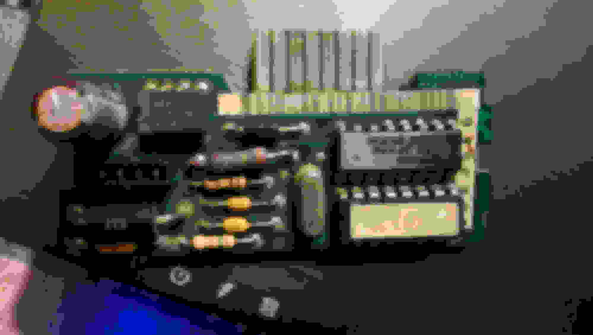
I removed by speedometer board and found it was pretty nasty and burnt looking (I won't say the outcome just yet... read on ).
Soot? Mold? Who knows.
It wasn't working, so I began following through the instructions in the referenced thread (the photo's there helped out immensely!).
The BIG resistor:
I measured the resistor and it showed only 3.9 ohms. I thought, "that's not right! Im'ma solder that bad boy off an' fix my speedo'!" My resistor actually seemed to have ferrous corrosion on one side, so I didn't even attempt to read it before it was off the board.
Once off, I got it flipped over and could see the lines a little better, they still didn't quite make since. Only three bands (20% tolerance)? Orange, brown (goldish?), gold (brownish?). That would be ~3.1 ohms. It measures 3.9 ohms. But with the stripes so far on the edges, i figured maybe a stripe was missing due to heat? eh... un-readable.
So I back checked OP's calculation on what appears to be an Orange, Black, Gold three band (3 ohms, 20% tolerance). Not 30 ohms? I'm not sure until someone else back checks me, now. I used a website I found google searching, "3 band resistor identification".
Then I found an ad for a speedometer circuit board for sale (wc-autoparts... out of stock...) and the pictured resistor was Orange (3), White (9), Gold (/10), Gold (+/- 1% tolerance); or 3.9 ohms!
For reference, my other two resistors by stripe color and measurement are 100 kohms (near the blade plug) and 15 kohms (at the edge of the board).
The Capacitors:
As ugly as the board looks, all the capacitors had good continuity to the board and seemed to function properly. I was not able to test the capacitors individually, but I read that if you measure them for resistance, they should drop to zero and the rise to something very high / near infinite resistance. All of mine seemed ok by this test.
The small yellow ones are from Kemet's Aximax line if you should go looking to replace any. I've id'd them as they appear to the best of my ability.
The signal test:
After I thought I had fixed my board the first time around, I started pulling my hair out when it still didn't work and decided it would [have] be[en] a good idea to check to make sure signal is actually getting to the speedo board [before tearing into the dash].
The easiest test I performed was using cruise control. I engaged the cruise control (in 5th @ ~ 2k rpm) and watched it properly hold speed. That indicated the VSS is working and the signal is being successfully interpreted by the ECM).
If you can't perform that test due to some issue with your cruise system, you can try one of the methods below.
For the manual transmission cars, the ECM keeps the RPM up when the vehicle speed is up to ensure you have vacuum to assist the brakes. If the wheels are rolling and the computers detects the increased speed (above ~5 mph) the rpm will tend to hoover around 1,500. This can be a good indicator that the ECM is getting signal from the VSS.
Automatics may a similar feature, but I'm not familiar enough to advise on what to look for there.
I read on another post that to check for signal on the 1227730 ECM with onboard VSS decoder, you can go to the C1 black plug (small one) with the tests being performed on the purple, yellow and brown wires in pins B9, B10 and B11, respectively.
With the vehicle running, rear tires off the ground and the multimeter switched to A/C voltage, I probed the purple and yellow wires with the car coming up off idle in fifth up to about 2k rpm. The voltage read from around 0.7 V at idle to about 4.5 V at what should have been almost 70 mph wheel speed. I moved the probe over to the brown wire and yellow wire and got the same voltage reading at the same RPMs.
At this point, I felt pretty confident that the problem was in the cluster.
A side note on the Brown and Yellow wire test... I'm not convinced it's quite the right test. I believe the signal going out through the brown wire is actually digital / binary and so it would appear as a step signal from 0 to the operating voltage of the speedometer board (12V?) Because the multimeter is so slow, it would probably average this signal and read some where around 6V if it's working (maybe 2.5V if it's a 5V signal). I'll update this after doing a little more research.
Fixing the Board: For me, I didn't really have to replace anything to get the board working. The metal layer on the top side of the board had corroded on one side of the big resistor and it was no longer connected to the board. I followed a trace on the board from the corroded side and found another location where it should be continuous. It wasn't, so I soldered a short wire from the pin of the resistor to the other pin location where the trace ended. After this, the board worked!, the speedometer worked! and I decided that what I had learned reading in other posts on here was so helpful, I should share!
Yeah! That ugly board works!
The greatest part about all this is that this is the last step in a series of repairs and revamps that SHOULD have the car inspected again for the first time in about EIGHT years.
Last edited by Elephantismo; Sep 24, 2015 at 01:36 AM.
Re: 1991 Camaro Speedometer Board; Broken, now working!
Elephantismo, mine is also a 3.9 ohm board. However my board has a different chip than yours. Probably because my board is with a 110 MPH speedo? I can also add that my instrument cluster is "25088982". Maybe the 25088984 is the one with the 30 ohm resistor? There seem to be so many variations with gauges and boards it keeps it so confusing!
My chip, labeled as:
2743
CS9126H
It also has a little black soot or whatever on it between the chip and capacitor and 3 connections are corroded + the solder connection that passes connection through the board- however every connection from/to that chip seems to be connected (verified with a volt/ohmmeter).
My Camaro (305 1992 Heritage Edition w/ automatic transmission) seems to know how fast it's going (connected my laptop to it via "WinALDL" I think it was?); it shows the MPH so from what I read that leaves out the VSS and likely the VSS Buffer? Although maybe the buffer could put out a good signal to the ECM but the side that sends the signal to the speedo is bad? Can't remember which is 2000ppm or 4000ppm- papers with info is in another room...
Anyway, I figure it's either:
1. the speedo (board likely) or
2. the VSS Buffer which I still haven't found yet (not behind the kick panel so I figure it's up behind the dash; problem is no glove box so I'd have to start removing panels or tearing the dash apart? Haven't looked into that yet...
Not really sure where to go from here... I have some pics of everything; just need to get around to connecting the camera to the 'puter and extracting them (camera's charging now- it'll be bedtime before that thing is charged LOL).
So does anyone have any ideas? I'm about ready to go to a junk yard and take the chance on another cluster and see what happens...
I can post the pics later if they would help anyone...
Re: 1991 Camaro Speedometer Board; Broken, now working!
FWIW, I would have cleaned up the board using a tooth brush and some rubbing alcohol. Doing so can ruin the stickers, but the dirt combined with humidity can cause minor conduction(Ie. shorts) across the surface. Once it's cleaned up I would go along the board and re-flow the solder joints with flux, or a small dab of flux based solder. Correct soldering procedure is key to fixing this vs. ruining it.
When you measure individual components, they must be removed from the circuit. Otherwise you are measuring the entire circuit that the resistor is connected to. You can measure as you mentioned if you compare to another board, or if you are checking specific points with known values.
The large electrolytic capacitor is old and I personally would change it because they tend to dry out over time. (They are polarized so if you do swap it make sure the new one is installed correctly or it will blow.) A capacitor can be thought of as a small rechargeable battery of sorts. When you check resistance, the meter puts out a voltage that “charges” up the capacitor which is why your measurement changes. Remember too that when you measure while it's connected you're actually measuring the entire circuit. You can leave the cap if you want, but if things seem to change when everything is warmed up I would swap that first as they are sensitive/responsive to heat -especially when old.
A side note on the Brown and Yellow wire test... I'm not convinced it's quite the right test. I believe the signal going out through the brown wire is actually digital / binary and so it would appear as a step signal from 0 to the operating voltage of the speedometer board (12V?) Because the multimeter is so slow, it would probably average this signal and read some where around 6V if it's working (maybe 2.5V if it's a 5V signal). I'll update this after doing a little more research.
I'm not as familiar with automotive Digital (or AC) electronics, however the principles are the same. Digital relies on a ground and a high voltage (I'm guessing 5v, but could be 12v etc.). Then, you have the trigger signal in-between the ground and high voltages. The trigger is based on passing by either up or down cycles of the waveform. So three (3) factors, and they are NOT variable. Analog is variable, digital is off/on via the up/down of the wave form. If your AC voltage is lower than it should be (or the ground faulty) then there is a possibility of false triggering. So your ground and high voltages need to be stable at all times. I'm not sure what you're measuring there with the variable voltages, but if it's digital the speed is measured via changes in the frequency, or how many cycles it passes through per unit of time.
The larger resistor is that way so it can handle more power. I forget off hand but it would have a higher wattage rating than the other ones around it (I'm guessing � watt vs. � watt?). It's been too long, but keep that in mind if you ever replace them. I even forgot how to read them but here are a couple of sites that may make it easier for you, they include 4,5, and 6 band: http://www.hobby-hour.com/electronic...calculator.php http://www.eeweb.com/toolbox/5-band-resistor-calculator
FWIW, the metal layer may have over heated and burned through. The traces run to what are called barrels that the resistor legs pass through, where the solder flows in and solidifies the connection. The trace wire you installed is standard procedure on repairing something like that. Try to make sure the the wire is thick enough though. If the wire is flopping around you can tack it down to the board. The board, btw is typically a fiberglass composite.
Good job on sticking with it, especially finding the information and following through. I hope you don't take my post the wrong way, I'm trying to fill you in on what you're doing do you have a better understanding of it.
Re: 1991 Camaro Speedometer Board; Broken, now working!
Originally Posted by avidgamr
My chip, labeled as:
2743
CS9126H
It also has a little black soot or whatever on it between the chip and capacitor and 3 connections are corroded + the solder connection that passes connection through the board- however every connection from/to that chip seems to be connected (verified with a volt/ohmmeter).
This looks like it might be your chip, a transistor or Frequency Generator. The "H" on the end will throw you off on a Google search, but otherwise you can sometimes find the chip by the number. HOWEVER, GM often covered up the manufacturers number and put a non-identifiable number in place of it. Also, the information is not as readily available as it used to be. http://alltransistors.com/transistor...ansistor=31691
Clean it up with some rubbing alcohol and a toothbrush or Q-tip and see what damage you actually have.
Re: 1991 Camaro Speedometer Board; Broken, now working!
Originally Posted by Scorpner
FWIW, I would have cleaned up the board using a tooth brush and some rubbing alcohol. Doing so can ruin the stickers, but the dirt combined with humidity can cause minor conduction(Ie. shorts) across the surface. Once it's cleaned up I would go along the board and re-flow the solder joints with flux, or a small dab of flux based solder. Correct soldering procedure is key to fixing this vs. ruining it.
When you measure individual components, they must be removed from the circuit. Otherwise you are measuring the entire circuit that the resistor is connected to. You can measure as you mentioned if you compare to another board, or if you are checking specific points with known values.
The large electrolytic capacitor is old and I personally would change it because they tend to dry out over time. (They are polarized so if you do swap it make sure the new one is installed correctly or it will blow.) A capacitor can be thought of as a small rechargeable battery of sorts. When you check resistance, the meter puts out a voltage that �charges� up the capacitor which is why your measurement changes. Remember too that when you measure while it's connected you're actually measuring the entire circuit. You can leave the cap if you want, but if things seem to change when everything is warmed up I would swap that first as they are sensitive/responsive to heat -especially when old.
I'm not as familiar with automotive Digital (or AC) electronics, however the principles are the same. Digital relies on a ground and a high voltage (I'm guessing 5v, but could be 12v etc.). Then, you have the trigger signal in-between the ground and high voltages. The trigger is based on passing by either up or down cycles of the waveform. So three (3) factors, and they are NOT variable. Analog is variable, digital is off/on via the up/down of the wave form. If your AC voltage is lower than it should be (or the ground faulty) then there is a possibility of false triggering. So your ground and high voltages need to be stable at all times. I'm not sure what you're measuring there with the variable voltages, but if it's digital the speed is measured via changes in the frequency, or how many cycles it passes through per unit of time.
The larger resistor is that way so it can handle more power. I forget off hand but it would have a higher wattage rating than the other ones around it (I'm guessing � watt vs. � watt?). It's been too long, but keep that in mind if you ever replace them. I even forgot how to read them but here are a couple of sites that may make it easier for you, they include 4,5, and 6 band: http://www.hobby-hour.com/electronic...calculator.php http://www.eeweb.com/toolbox/5-band-resistor-calculator
FWIW, the metal layer may have over heated and burned through. The traces run to what are called barrels that the resistor legs pass through, where the solder flows in and solidifies the connection. The trace wire you installed is standard procedure on repairing something like that. Try to make sure the the wire is thick enough though. If the wire is flopping around you can tack it down to the board. The board, btw is typically a fiberglass composite.
Good job on sticking with it, especially finding the information and following through. I hope you don't take my post the wrong way, I'm trying to fill you in on what you're doing do you have a better understanding of it.
Thanks but the quote (brown and yellow wire test) you gave was not my posting- it was the original OP post (Elephantismo) so the info referring to that doesn't apply to me...
Oh, and I wasn't actually *measuring* any components, I was just checking continuity between traces on the board to ensure everything was actually flowing electricity through to other components. Everything checked fine, however, as you said, maybe I was getting a false reading from other components? I will try the cleaning and see what comes from it. Thanks for the as I was trying to figure out how to clean up the corrosive soot (or whatever it is) that's beginning to appear (as in the original OP's post) but wasn't sure what to use or how to do it. That seems like a better idea that anything I had thought of!
Oh, and pics are attached for everyone to see. Have more I can post if needed!
Re: 1991 Camaro Speedometer Board; Broken, now working!
Originally Posted by avidgamr
Thanks but the quote (brown and yellow wire test) you gave was not my posting- it was the original OP post (Elephantismo) so the info referring to that doesn't apply to me...
Oh, and I wasn't actually *measuring* any components, I was just checking continuity between traces on the board to ensure everything was actually flowing electricity through to other components. Everything checked fine, however, as you said, maybe I was getting a false reading from other components? I will try the cleaning and see what comes from it. Thanks for the as I was trying to figure out how to clean up the corrosive soot (or whatever it is) that's beginning to appear (as in the original OP's post) but wasn't sure what to use or how to do it. That seems like a better idea that anything I had thought of!
Oh, and pics are attached for everyone to see. Have more I can post if needed!
Yep, the first post was replying to the OP. It was more of a hassle to pull the entire quote and find the part I wanted to take out. I hope it helps anyone though as the info is pretty much standard in the industry.
I wouldn't say it's a false reading as the reading should be the same from board to board. It won't typically single out a single component though.
You're welcome! That corrosive soot looks more like a lot of current went through it, or in other words a high current short. There may be damage to the barrel and traces as well. You may find similar issues on the back side.
Re: 1991 Camaro Speedometer Board; Broken, now working!
That's the only place with any signs of anything; the remainder looks like NOS.
Pic of other side is attached.
So I guess what I'm facing is fried chip? The capacitor seems to test ok although I must admit I'm an amateur when it comes to testing caps. The cap measured (with an ESR meter):
142uF / ESR = 0.75. Cap is 150uF so 142 is within the 20%. No idea on the ESR... Can't find a spec sheet on the cap. Not completely sure of those numbers as I still don't quite know how to use this meter yet. Afterwards I saw in the manual about calibrating the meter for use with the leads so that it takes in account the ohms of the meter leads... http://www.radiodevices.info/esr/esr4_en.pdf
So if anybody understands these numbers or has any suggestions please chime in!
Appreciate the help Scorpner! Keep it coming!
Re: 1991 Camaro Speedometer Board; Broken, now working!
Yes, I noticed how clean the board is otherwise. I'm surprised that it didn't show up on the back side though. You could try re-flowing that to see if it cleans up more.
As I was saying, the electrolytic cap is old, the performance can also degrade as it warms up. Because of that, even if a tester says it's good, it can still fail intermittently and/or over time. I've never tested them on the repairs at work either because we knew which ones commonly failed and replaced as a preventative measure. Sometimes the circuit design leads to premature cap failure, or an outside factor causes it to fail. On ours I would determine which it was and repair accordingly.
So replacing both the chip and cap on yours may not always fix the actual problem, but that gets into more involved testing where you would know the common voltages and/or reverse engineer the circuit. I just looked and this style of cap can fail as a short (I thought I recalled that they failed open). But for that additional reason I would at least replace the cap.
Electrolytic capacitors
In addition to the problems listed above, electrolytic capacitors suffer from these failures:
Aluminium versions having their electrolyte dry out for a gradual leakage, equivalent series resistance and loss of capacitance. Power dissipation by high ripple currents and internal resistances cause an increase of the capacitor's internal temperature beyond specifications, accelerating the deterioration rate; such capacitors usually fail short.[2]
Electrolyte contamination (like from moisture) corroding the electrodes, leading to capacitance loss and shorts.[2]
A capacitor can fail shorted which is probably the worst thing that could happen. This is one of the reasons why it is important to replace capacitors which are failing early. A shorted capacitor would probably damage the motherboard to an extent that it would be impossible to easily repair requiring components to be taken from a donor board and used as replacements. It is possible for a capacitor to fail shorted also with no visible signs.
Re: 1991 Camaro Speedometer Board; Broken, now working!
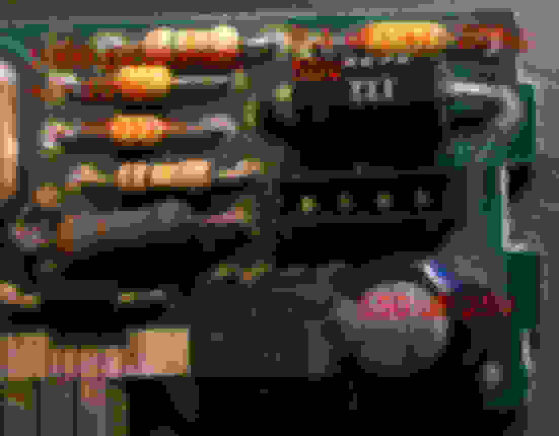
If you look at the second picture in post#1, the large electrolytic looks to be puffed which means it overheated. If so, it probably caused the sooty, greasy film on the board. As Scorpner suggested, replace it. Avidgamr's looks to be leaking a little also, causing the grime around that area. Should probably be replaced also. HTH!
Oh, BTW, alcohol is a good cleaner to use as it will not hurt the substrate and does a pretty good job of cleaning. An aerosol alternative is CRC Contact Cleaner. WARNING! Contact Cleaner will attack some plastics so be careful!
Re: 1991 Camaro Speedometer Board; Broken, now working!
So busy these days; took a while to get back on here! Thanks for the replies!
The capacitor doesn't really look swelled to me and seemed to test withing the microfarad it's supposed to be but I'm game for anything to try to get my Camaro back on the road again! LOL
So what do I look for in a replacement capacitor? Radio Shack doesn't seem to have any 150uf 25v caps in stock? At least not on their website. Even if they did, I'm thinking they'd be general purpose and not low esr, which I believe is what I need?
To my understanding of caps I can use a cap that's rated for higher voltage (60vdc in place of a 25vdc for example) but the microfarad/picofarad, tolerance of 20% and, if applicable, low esr must be the same, correct?
Re: 1991 Camaro Speedometer Board; Broken, now working!
Been doing research finally...
Found the datasheet on my cap (nichicon PF series). It's low esr, rated 0.33 ohms impedance max @ 68 degrees F. That means my cap is definitely bad as it measured 0.75! Thanks guys! Time to order a cap!
Re: 1991 Camaro Speedometer Board; Broken, now working!
When you measure a capacitor with an ohm meter, the resistance reading should start out low and climb to infinite as it charges. Any cap that does not exhibit this action is bad. A cap that reads 0.75 ohms and does not climb to infinite is shorted and needs to be replaced. GL!
Re: 1991 Camaro Speedometer Board; Broken, now working!
Oh, you're using an ESR (equivalent series resistance) meter which works differently from an ohm meter. The ESR is basically the AC impedance of the cap as measured at a given temp and AC frequency. If the ESR has drifted that far, you do need to replace the cap.
Re: 1991 Camaro Speedometer Board; Broken, now working!
Originally Posted by Elephantismo
This thread was very helpful in driving me to fix my 145 mph speedometer board, but I think I have a few corrections and edits, specifically for the large resistor ID'd as 30 ohms.
I dove into the task of pulling my gauge cluster and disassembling it somewhat on a whim and lucked out. The symptoms were intermittent / random loss of speedometer reading. Bumping things like the dash, ecm, etc didn't help. Wiggling plugs didn't help, so I was already leaning pretty well towards the gauge cluster.
I'm giving a run through of what I encountered in hopes that it helps someone else to fix theirs.
First, I'm going to add my observations.
I removed by speedometer board and found it was pretty nasty and burnt looking (I won't say the outcome just yet... read on ).
Soot? Mold? Who knows.
It wasn't working, so I began following through the instructions in the referenced thread (the photo's there helped out immensely!).
The BIG resistor:
I measured the resistor and it showed only 3.9 ohms. I thought, "that's not right! Im'ma solder that bad boy off an' fix my speedo'!" My resistor actually seemed to have ferrous corrosion on one side, so I didn't even attempt to read it before it was off the board.
Once off, I got it flipped over and could see the lines a little better, they still didn't quite make since. Only three bands (20% tolerance)? Orange, brown (goldish?), gold (brownish?). That would be ~3.1 ohms. It measures 3.9 ohms. But with the stripes so far on the edges, i figured maybe a stripe was missing due to heat? eh... un-readable.
So I back checked OP's calculation on what appears to be an Orange, Black, Gold three band (3 ohms, 20% tolerance). Not 30 ohms? I'm not sure until someone else back checks me, now. I used a website I found google searching, "3 band resistor identification".
Then I found an ad for a speedometer circuit board for sale (wc-autoparts... out of stock...) and the pictured resistor was Orange (3), White (9), Gold (/10), Gold (+/- 1% tolerance); or 3.9 ohms!
For reference, my other two resistors by stripe color and measurement are 100 kohms (near the blade plug) and 15 kohms (at the edge of the board).
The Capacitors:
As ugly as the board looks, all the capacitors had good continuity to the board and seemed to function properly. I was not able to test the capacitors individually, but I read that if you measure them for resistance, they should drop to zero and the rise to something very high / near infinite resistance. All of mine seemed ok by this test.
The small yellow ones are from Kemet's Aximax line if you should go looking to replace any. I've id'd them as they appear to the best of my ability.
The signal test:
After I thought I had fixed my board the first time around, I started pulling my hair out when it still didn't work and decided it would [have] be[en] a good idea to check to make sure signal is actually getting to the speedo board [before tearing into the dash].
The easiest test I performed was using cruise control. I engaged the cruise control (in 5th @ ~ 2k rpm) and watched it properly hold speed. That indicated the VSS is working and the signal is being successfully interpreted by the ECM).
If you can't perform that test due to some issue with your cruise system, you can try one of the methods below.
For the manual transmission cars, the ECM keeps the RPM up when the vehicle speed is up to ensure you have vacuum to assist the brakes. If the wheels are rolling and the computers detects the increased speed (above ~5 mph) the rpm will tend to hoover around 1,500. This can be a good indicator that the ECM is getting signal from the VSS.
Automatics may a similar feature, but I'm not familiar enough to advise on what to look for there.
I read on another post that to check for signal on the 1227730 ECM with onboard VSS decoder, you can go to the C1 black plug (small one) with the tests being performed on the purple, yellow and brown wires in pins B9, B10 and B11, respectively.
With the vehicle running, rear tires off the ground and the multimeter switched to A/C voltage, I probed the purple and yellow wires with the car coming up off idle in fifth up to about 2k rpm. The voltage read from around 0.7 V at idle to about 4.5 V at what should have been almost 70 mph wheel speed. I moved the probe over to the brown wire and yellow wire and got the same voltage reading at the same RPMs.
At this point, I felt pretty confident that the problem was in the cluster.
A side note on the Brown and Yellow wire test... I'm not convinced it's quite the right test. I believe the signal going out through the brown wire is actually digital / binary and so it would appear as a step signal from 0 to the operating voltage of the speedometer board (12V?) Because the multimeter is so slow, it would probably average this signal and read some where around 6V if it's working (maybe 2.5V if it's a 5V signal). I'll update this after doing a little more research.
Fixing the Board:
For me, I didn't really have to replace anything to get the board working. The metal layer on the top side of the board had corroded on one side of the big resistor and it was no longer connected to the board. I followed a trace on the board from the corroded side and found another location where it should be continuous. It wasn't, so I soldered a short wire from the pin of the resistor to the other pin location where the trace ended. After this, the board worked!, the speedometer worked! and I decided that what I had learned reading in other posts on here was so helpful, I should share!
Yeah! That ugly board works!
The greatest part about all this is that this is the last step in a series of repairs and revamps that SHOULD have the car inspected again for the first time in about EIGHT years.
YES! Thank you for the correction of the 30ohm to 3.0ohm. Atleast my post did help some haha, the car I made the post with the speedometer worked up until November 2018 when the car got totaled out from someone rearending me. I always wondered if my 30ohm setup ever effected anything, as with GPS and tunerpro everything read within 0.5-1mph difference with 235/60R15 tires. There might be more tolerance then we know and the higher resistance might possibly reduce some voltage and possibly keeping these boards from burning up? I now have a 92 with a 110mph gauge and swapping to the 145mph, so I may need your help with the 145mph if I cannot get the board working lol.
Great post and thank you again for correcting my mistake as well.
Re: 1991 Camaro Speedometer Board; Broken, now working!
Scorpner, just wanted to say thank you for your insight. I've not progressed much with the car but everything is ok for now. I may still pull it and clean and replace if i ever get through with body work.


 ).
).


 I'm about ready to go to a junk yard and take the chance on another cluster and see what happens...
 as I was trying to figure out how to clean up the corrosive soot (or whatever it is) that's beginning to appear (as in the original OP's post) but wasn't sure what to use or how to do it. That seems like a better idea that anything I had thought of!


