
LS1 swap for my '89 GTA


Re: LS1 swap for my '89 GTA
89 C207
A Not used
B INJ 1
C MIL
D Fan fuse
E Not used
F PCM Fuse
G INJ 2 fuse
H Not used
J Not used
K Speedo (remember to bypass the buffer box
L Not used
M Cluster GRD
N Not used
P Not used
R Not used
Your fuel pump wire goes through the C100 for 89's. Thats what makes them unique compared to older harnesses
A standard pencil iron isnt enough to heat up the 10-12ga wires. Use a 30A gun style iron instead. Id suggest cutting all those butt crimps out and soldering the joint. They will fail, maybe next year, maybe 10 years down the road
For your alt, Id strongly suggest using R15 instead of any other IGN source
Id skip the fusible links completely and just crimp ring terminals on for a quick junction at the power dist block. 1) They're a pain from the factory as its hard to tell if they're good or bad and are not easy to replace. 2) If you run everything to a factory fuse point, all the IGN points will be fused already, so its an unnecessary redundancy
The pictured power dist block can be found on most 90's GM pick-up trucks, but the cover is late 90's S10/blazer exclusive

Supreme Member
iTrader: (2)
Joined: Jan 2001
Posts: 4,149
Likes: 3
From: Tampa, FL, USA
Car: 93 240SX
Engine: LQ9
Transmission: T56
Axle/Gears: 3.54 R200 IRS
Re: LS1 swap for my '89 GTA
Id skip the fusible links completely and just crimp ring terminals on for a quick junction at the power dist block. 1) They're a pain from the factory as its hard to tell if they're good or bad and are not easy to replace. 2) If you run everything to a factory fuse point, all the IGN points will be fused already, so its an unnecessary redundancy
The pictured power dist block can be found on most 90's GM pick-up trucks, but the cover is late 90's S10/blazer exclusive
Thread Starter
Supreme Member
iTrader: (1)
Joined: Mar 2007
Posts: 1,237
Likes: 7
From: Apopka, Florida
Car: 1989 Pontiac Trans Am GTA
Engine: cammed LS1
Transmission: Monster SS 4L65E
Axle/Gears: 9 bolt posi w/ 3.70 gears
Re: LS1 swap for my '89 GTA
Thanks guys for the input.
Pocket, butt crimps already have been removed. Heavy gauge wires are now soldered together using a higher powered gun. The alternator is already connected to R15. My C207 wires are now correct except for K & M. I will get into K in the next paragraph about my VSS. You said M is the cluster GRD. Does that mean I should run a wire from M to the common grounds that connect to the cylinder heads?
VSS... I am still trying to wrap my head around this, but it's very confusing. So many VSS wires! On the C100 there's D4 & E4, at the speedo buffer box there appears to be VSS wires there (ppl & yel wires into a two pin connector), There is the VSS sensor on the end of the trany & there are three pins on the ECM for VSS (R20 low, R21 high & R50 signal)
  Does the VSS signal from R50 connect to C207K? Based on this quote:
and this diagram:
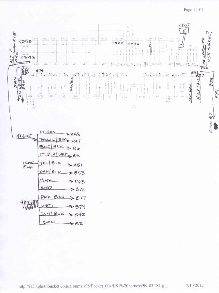
Here is a crude VSS wiring diagram that I drew-up to see if I am on the right track or not:

Hopefully I got it right.
Charcoal Canister wires... green/yellow to R34 & pink/blk to C100 A7?
HO2's pink wires to C100 F4?
MAF pink wire shows a 15a fuse on your diagrams. I didn't see a 15a fuse in the fuse block, so I'm a bit confused on that. See pic
I also haven't found the ALDL yet. And I haven't found P/Neutral yet either. Sorry for all of the questions. I just want to make sure I understand everything before you go out of town again
Pocket, butt crimps already have been removed. Heavy gauge wires are now soldered together using a higher powered gun. The alternator is already connected to R15. My C207 wires are now correct except for K & M. I will get into K in the next paragraph about my VSS. You said M is the cluster GRD. Does that mean I should run a wire from M to the common grounds that connect to the cylinder heads?
VSS... I am still trying to wrap my head around this, but it's very confusing. So many VSS wires!
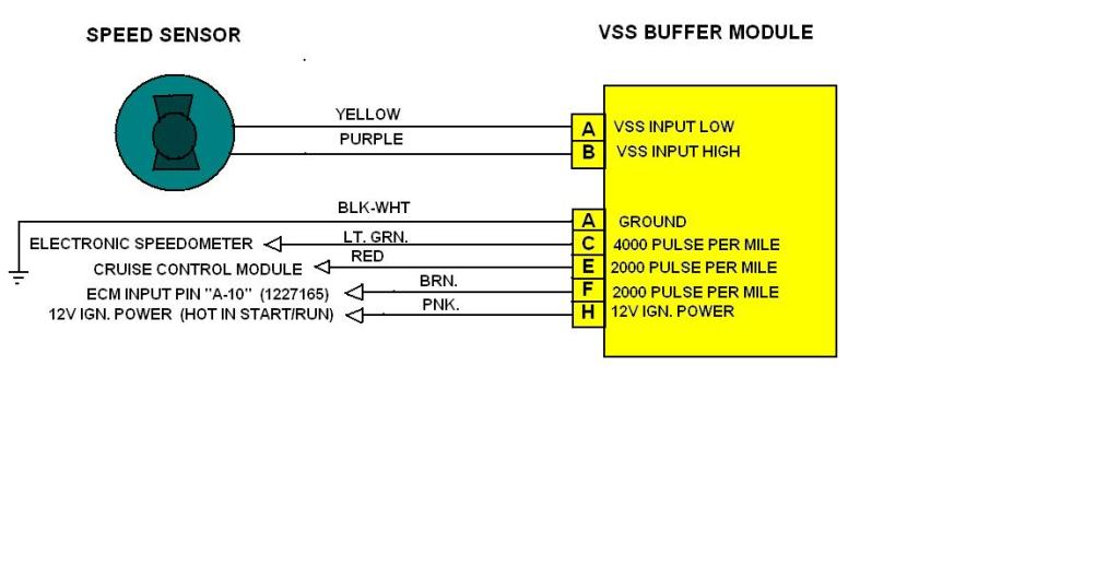
On the C100 there's D4 & E4, at the speedo buffer box there appears to be VSS wires there (ppl & yel wires into a two pin connector), There is the VSS sensor on the end of the trany & there are three pins on the ECM for VSS (R20 low, R21 high & R50 signal) Does the VSS signal from R50 connect to C207K? Based on this quote:Yellow box is your buffer. Remove and connect pins C to F
http://www.austinthirdgen.org/mkport...SS_V8_vinE.jpg
http://www.austinthirdgen.org/mkport...SS_V8_vinE.jpg
Here is a crude VSS wiring diagram that I drew-up to see if I am on the right track or not:
Hopefully I got it right.
Charcoal Canister wires... green/yellow to R34 & pink/blk to C100 A7?
HO2's pink wires to C100 F4?
MAF pink wire shows a 15a fuse on your diagrams. I didn't see a 15a fuse in the fuse block, so I'm a bit confused on that. See pic
I also haven't found the ALDL yet. And I haven't found P/Neutral yet either. Sorry for all of the questions. I just want to make sure I understand everything before you go out of town again
Last edited by dprest68; Jul 21, 2012 at 12:01 PM. Reason: added pic
Re: LS1 swap for my '89 GTA
This should not be followed, there is no "factory fuse point" to safely and properly supply the harness, if someone was that determined to remove the factory fusible links a fuse holder would need to be installed inline in place of each fusible link, or each of the wires routed to a seperate fuse block and connected with one fuse for each.
You said M is the cluster GRD. Does that mean I should run a wire from M to the common grounds that connect to the cylinder heads?
You're thinking too much into the speedo. From the factory the older ECMs were not capable of understanding the raw VSS data, so it was sent to the buffer box to be cut down to something the ECM can understand, then split to the cluster, ECM and cruise module. Since the LSx PCM is plenty capable you can skip almost all of it
On the back of the trans is the VSS, it has two wires that run to the PCM uninterrupted. The PCM handles the rest and has a single output at R50. You can either run this directly to the cluster and tap in somewhere or use pin K on the C207. For the C207 route, you must find the buffer box and jumper pins C and F so its a strait shot to the cluster. Leave the buffer box unplugged as it will no longer be used
From the factory, the VSS wires did not go to the ECM first, they went to the buffer box to be decoded and split to the cluster, ECM and cruise module. Jumping the pins at the box connects the cluster and ECM lines so its a direct route. The rest of the old circuit is no longer used as the new harness has the job covered
Supreme Member
iTrader: (2)
Joined: Jan 2001
Posts: 4,149
Likes: 3
From: Tampa, FL, USA
Car: 93 240SX
Engine: LQ9
Transmission: T56
Axle/Gears: 3.54 R200 IRS
Re: LS1 swap for my '89 GTA
Something wrong with the factory INJ 1/2, PCM, Fan, fuel pump etc fuses? Adding a second fuseblock when the first is already wired in and adequate for the job is pointless. On older cars like classics and carb'd third gens, sure you need to add a separate fuseblock because several fuse points are not present, but later EFI cars like his 89 are perfectly capable of supporting the new electronics on the old fuse points
NOTHING, please learn and understand here.
The links protect the wires between the BATTERY and the FUSE BLOCK, NOTHING beyond that, every single fuse would have to be replaced with a straight connection and then every component after the fuse short out to pop the link if they were for what you seem to believe. They arent, please learn what the function of the component is before you determine its uselessness.

Member
Joined: Jan 2011
Posts: 173
Likes: 1
From: Nashville, TN
Car: 1988 Camaro Iroc-Z Convertible
Engine: LS1
Transmission: T56
Axle/Gears: 8.8 with 4.10 Gears
Re: LS1 swap for my '89 GTA
Man your swap is looking great! It's definitely motivation to make mine look even better. I saw that you had your engine bay painted as well. Do you know of any way to install those speed clips that are used for virtually all of the bolts in the engine bay without scratching the paint. It seems like those things are such a tight fit there's no way around it, but I figured I'd ask anyway.
Thread Starter
Supreme Member
iTrader: (1)
Joined: Mar 2007
Posts: 1,237
Likes: 7
From: Apopka, Florida
Car: 1989 Pontiac Trans Am GTA
Engine: cammed LS1
Transmission: Monster SS 4L65E
Axle/Gears: 9 bolt posi w/ 3.70 gears
Re: LS1 swap for my '89 GTA
Thanks V8SC! Are you are talking about the clip-on nuts that most of the bolts connect into? If so, then yeah, I scratched the paint on mine a few times before I realized that I should just open the nut-clip up a little more with a flat head screw driver. it makes for a loose fit, but tightens up once you tighten the bolt into it.
Member
Joined: Jan 2011
Posts: 173
Likes: 1
From: Nashville, TN
Car: 1988 Camaro Iroc-Z Convertible
Engine: LS1
Transmission: T56
Axle/Gears: 8.8 with 4.10 Gears
Re: LS1 swap for my '89 GTA
Yeah I scratched my paint a little on a couple of them. Luckily it is under the clip itself. I'll have to see what I can do to open those up a little. They seem to have quite a bit of tension on them. I don't want to be scratching my new paint up anymore than I have to.
Thread Starter
Supreme Member
iTrader: (1)
Joined: Mar 2007
Posts: 1,237
Likes: 7
From: Apopka, Florida
Car: 1989 Pontiac Trans Am GTA
Engine: cammed LS1
Transmission: Monster SS 4L65E
Axle/Gears: 9 bolt posi w/ 3.70 gears
Re: LS1 swap for my '89 GTA
Yeah, I hear ya.
See if this helps

thread the bolt into the nut, clamp the bolt head into the vice then use a large flat head screw driver to pry up on the clip part to loosen it a bit.
See if this helps
thread the bolt into the nut, clamp the bolt head into the vice then use a large flat head screw driver to pry up on the clip part to loosen it a bit.
Thread Starter
Supreme Member
iTrader: (1)
Joined: Mar 2007
Posts: 1,237
Likes: 7
From: Apopka, Florida
Car: 1989 Pontiac Trans Am GTA
Engine: cammed LS1
Transmission: Monster SS 4L65E
Axle/Gears: 9 bolt posi w/ 3.70 gears
Re: LS1 swap for my '89 GTA
Weekend wiring questions:
1. It looks like HO2's, MAF, trany & charcoal canister all connect to the emissions common wire (C100 A7) for a fused connection, correct?
2. all other hot wires connect to the fat pink wire from C100 F4, right?
3. Charcoal Canister wires... green/yellow to R34 & pink/blk to C100 A7?
4. Are the park/neutral wires & ALDL wires near the old ECM location or do I need to disassemble part of the interior to track these wires down? Feel free to provide pics
5. If I want to keep my stock cruise control will I still need the buffer box? Or can I just jump C & E over to F?
Everything else is pretty much wired up. So once I get these questions answered I'll be able to wrap it up.
Thread Starter
Supreme Member
iTrader: (1)
Joined: Mar 2007
Posts: 1,237
Likes: 7
From: Apopka, Florida
Car: 1989 Pontiac Trans Am GTA
Engine: cammed LS1
Transmission: Monster SS 4L65E
Axle/Gears: 9 bolt posi w/ 3.70 gears
Re: LS1 swap for my '89 GTA
Well, I guess Pocket wasn't around this weekend. I guess I'll have to call him with my list of questions. I want to get this harness wrapped-up this week & get this engine in the car.
Member
iTrader: (3)
Joined: Jul 2008
Posts: 385
Likes: 0
From: ND
Car: 1986 Firebird
Engine: 6.0L LSX
Transmission: 4L60E
Axle/Gears: 3.73
Re: LS1 swap for my '89 GTA
Not sure on the charcoal canister and all that other stuff...I deleted mine.
ALDL goes from ECU to the plug under the driver side dash. Look for the pin that is classified as "Class 2 Serial Data" on your ECU (in my case it was B58) and plug into pin 2 on ALDL port...
http://www.lt1swap.com/fuseblock_obd2port.html
look at this site at the bottom of the page. Easier than me trying to explain.
Member
Joined: Jan 2011
Posts: 173
Likes: 1
From: Nashville, TN
Car: 1988 Camaro Iroc-Z Convertible
Engine: LS1
Transmission: T56
Axle/Gears: 8.8 with 4.10 Gears
Re: LS1 swap for my '89 GTA
For what it's worth, Pocket told me last weekend that he'd be out of town for 2 weeks. He essentially said he wouldn't be able to answer any PM's while he was gone.
Thread Starter
Supreme Member
iTrader: (1)
Joined: Mar 2007
Posts: 1,237
Likes: 7
From: Apopka, Florida
Car: 1989 Pontiac Trans Am GTA
Engine: cammed LS1
Transmission: Monster SS 4L65E
Axle/Gears: 9 bolt posi w/ 3.70 gears
Re: LS1 swap for my '89 GTA
Thanks Mille & thanks for the info V8SC. I texted him and he is supposed to call me later this afternoon
Member
Joined: Jan 2011
Posts: 173
Likes: 1
From: Nashville, TN
Car: 1988 Camaro Iroc-Z Convertible
Engine: LS1
Transmission: T56
Axle/Gears: 8.8 with 4.10 Gears
Re: LS1 swap for my '89 GTA
Not sure on the charcoal canister and all that other stuff...I deleted mine.
ALDL goes from ECU to the plug under the driver side dash. Look for the pin that is classified as "Class 2 Serial Data" on your ECU (in my case it was B58) and plug into pin 2 on ALDL port...
http://www.lt1swap.com/fuseblock_obd2port.html
look at this site at the bottom of the page. Easier than me trying to explain.
ALDL goes from ECU to the plug under the driver side dash. Look for the pin that is classified as "Class 2 Serial Data" on your ECU (in my case it was B58) and plug into pin 2 on ALDL port...
http://www.lt1swap.com/fuseblock_obd2port.html
look at this site at the bottom of the page. Easier than me trying to explain.
Thread Starter
Supreme Member
iTrader: (1)
Joined: Mar 2007
Posts: 1,237
Likes: 7
From: Apopka, Florida
Car: 1989 Pontiac Trans Am GTA
Engine: cammed LS1
Transmission: Monster SS 4L65E
Axle/Gears: 9 bolt posi w/ 3.70 gears
Re: LS1 swap for my '89 GTA
I read that if you leave that line open you have the possibility of getting the strong fuel vapor smell. I'm not taking that chance.
Thread Starter
Supreme Member
iTrader: (1)
Joined: Mar 2007
Posts: 1,237
Likes: 7
From: Apopka, Florida
Car: 1989 Pontiac Trans Am GTA
Engine: cammed LS1
Transmission: Monster SS 4L65E
Axle/Gears: 9 bolt posi w/ 3.70 gears
Re: LS1 swap for my '89 GTA
Oh man, you have no idea! I am pretty close to being done with it though. So yay for that
Pocket called me this evening. So I'm pretty sure I got most of my questions answered. The only thing that he couldn't answer from his memory was how to wire the A/C. He gave me an idea where to look though. So I have been researching that this evening.
Pocket called me this evening. So I'm pretty sure I got most of my questions answered. The only thing that he couldn't answer from his memory was how to wire the A/C. He gave me an idea where to look though. So I have been researching that this evening.
Member
iTrader: (3)
Joined: Jul 2008
Posts: 385
Likes: 0
From: ND
Car: 1986 Firebird
Engine: 6.0L LSX
Transmission: 4L60E
Axle/Gears: 3.73
Re: LS1 swap for my '89 GTA
I capped the line and am using a vented gas cap instead. No more smell than any other of my cars.
Re: LS1 swap for my '89 GTA
Your tank already has a vent, but since its over 20 years old a replacement wouldnt hurt. I got a new one from the HELP section of advance auto and capped my EVAP line. No gas smell in the garage that Ive noticed
Thread Starter
Supreme Member
iTrader: (1)
Joined: Mar 2007
Posts: 1,237
Likes: 7
From: Apopka, Florida
Car: 1989 Pontiac Trans Am GTA
Engine: cammed LS1
Transmission: Monster SS 4L65E
Axle/Gears: 9 bolt posi w/ 3.70 gears
Re: LS1 swap for my '89 GTA
Since Pocket is in town, I figured I better post my wiring questions before he leaves again
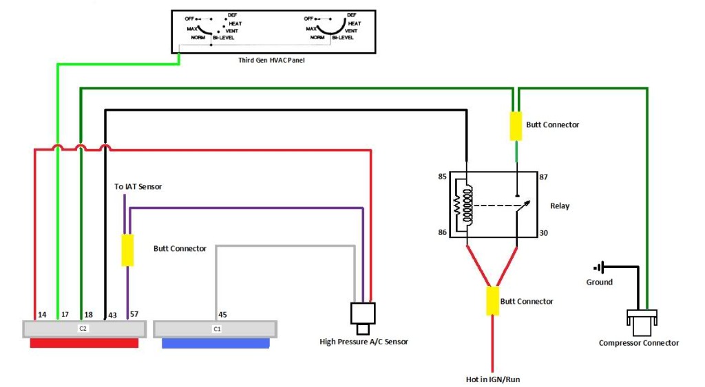
Based on our conversation the other night, I think I now have a good grasp on almost everything wiring related. Here's an HVAC wiring diagram I found on Dynodanmanda79's swap thread. Thanks!
Well, it took me awhile to figure out how to get my drawing converted over to JPG, then it hit me... SCAN IT! Anyways, here's my LS1 PCM pin-out map for wiring dummies... That would be me!

I whipped this out real quick. Yeah, right! It took me all day
99-02 LS1 CONNECTIONS.pdf Here's the PDF in case anyone wants it. It shows the colors on the drawing that the scan doesn't.
I think my only real question was where to connect the hot wire for the A/C relay. On fat pink wire from C100 or emissions common wire or elsewhere? Pocket, or anyone smarter than me at wiring, can you please look my diagram over and tell me if everything looks correct to you. I would really appreciate it.
Based on our conversation the other night, I think I now have a good grasp on almost everything wiring related. Here's an HVAC wiring diagram I found on Dynodanmanda79's swap thread. Thanks!
Well, it took me awhile to figure out how to get my drawing converted over to JPG, then it hit me... SCAN IT!
Anyways, here's my LS1 PCM pin-out map for wiring dummies... That would be me! I whipped this out real quick. Yeah, right! It took me all day
99-02 LS1 CONNECTIONS.pdf Here's the PDF in case anyone wants it. It shows the colors on the drawing that the scan doesn't.
I think my only real question was where to connect the hot wire for the A/C relay. On fat pink wire from C100 or emissions common wire or elsewhere? Pocket, or anyone smarter than me at wiring, can you please look my diagram over and tell me if everything looks correct to you. I would really appreciate it.
Thread Starter
Supreme Member
iTrader: (1)
Joined: Mar 2007
Posts: 1,237
Likes: 7
From: Apopka, Florida
Car: 1989 Pontiac Trans Am GTA
Engine: cammed LS1
Transmission: Monster SS 4L65E
Axle/Gears: 9 bolt posi w/ 3.70 gears
Re: LS1 swap for my '89 GTA
Oops, I lied! I still have ALDL questions! Mille posted a link on here for the ALDL, but it looks like it was actually for OBD2 instead. Here's a pic of my ALDL port & wires

I just need to know where to connect the four wires on here. (power, two grounds & PCM output) Also, are the other wires not used left connected or should they be removed?
Okay, I'll stop being so needy now!
Mille posted a link on here for the ALDL, but it looks like it was actually for OBD2 instead. Here's a pic of my ALDL port & wiresI just need to know where to connect the four wires on here. (power, two grounds & PCM output) Also, are the other wires not used left connected or should they be removed?
Okay, I'll stop being so needy now!
Re: LS1 swap for my '89 GTA
I think my only real question was where to connect the hot wire for the A/C relay. On fat pink wire from C100 or emissions common wire or elsewhere?
Where did you find that diagram? I dont recall ever drawing it
I just need to know where to connect the four wires on here. (power, two grounds & PCM output) Also, are the other wires not used left connected or should they be removed?
Thread Starter
Supreme Member
iTrader: (1)
Joined: Mar 2007
Posts: 1,237
Likes: 7
From: Apopka, Florida
Car: 1989 Pontiac Trans Am GTA
Engine: cammed LS1
Transmission: Monster SS 4L65E
Axle/Gears: 9 bolt posi w/ 3.70 gears
Re: LS1 swap for my '89 GTA
Thanks Pocket. So it sounds like I need to get an OBDII port off of a 4th gen then. That makes more sense.
I drew that diagram up myself on Friday. It actually helped me to understand a few things a little better when I did it too. Did you look it over real good to make sure everything looked okay on it?
I drew that diagram up myself on Friday.
It actually helped me to understand a few things a little better when I did it too. Did you look it over real good to make sure everything looked okay on it? Last edited by dprest68; Aug 4, 2012 at 11:53 PM.
Thread Starter
Supreme Member
iTrader: (1)
Joined: Mar 2007
Posts: 1,237
Likes: 7
From: Apopka, Florida
Car: 1989 Pontiac Trans Am GTA
Engine: cammed LS1
Transmission: Monster SS 4L65E
Axle/Gears: 9 bolt posi w/ 3.70 gears
Re: LS1 swap for my '89 GTA
Wiring diagram revised 99-02 LS1 CONNECTIONS REV1.pdf (updated 8/6/12)
What size fuse should I put between the new A/C relay & the fat pink wire?
I'm working on drawing up a 1989 C100 wiring diagram similar to your 90-92 diagram
What size fuse should I put between the new A/C relay & the fat pink wire?
I'm working on drawing up a 1989 C100 wiring diagram similar to your 90-92 diagram
Last edited by dprest68; Aug 6, 2012 at 09:28 AM. Reason: updated attachment
Thread Starter
Supreme Member
iTrader: (1)
Joined: Mar 2007
Posts: 1,237
Likes: 7
From: Apopka, Florida
Car: 1989 Pontiac Trans Am GTA
Engine: cammed LS1
Transmission: Monster SS 4L65E
Axle/Gears: 9 bolt posi w/ 3.70 gears
Re: LS1 swap for my '89 GTA
More Diagrams For Dummies
1989 C100 and C207 Connections.pdf
This one went a lot quicker. This should cover the rest of the connections for the '89 swap including C100 & C207. Let me know what you think.
1989 C100 and C207 Connections.pdf
This one went a lot quicker. This should cover the rest of the connections for the '89 swap including C100 & C207. Let me know what you think.
Thread Starter
Supreme Member
iTrader: (1)
Joined: Mar 2007
Posts: 1,237
Likes: 7
From: Apopka, Florida
Car: 1989 Pontiac Trans Am GTA
Engine: cammed LS1
Transmission: Monster SS 4L65E
Axle/Gears: 9 bolt posi w/ 3.70 gears
Re: LS1 swap for my '89 GTA
I spent the first half of the day at Hooters & Hot Rods in Sanford with Luis (Motobooks). Other than my beater...

there was only one other third gen there and he wasn't even there for the show.

The second half of the day I worked on my car.
I got the stock cruise control harness cleaned-up & back in the car
I filed the cable bracket on the intake manifold to accept the stock cruise control cable

It fits like a glove now

The C207 pigtail is all connected except for the fan wire
And I tested all of the C100 wires for resistance and all is good
there was only one other third gen there and he wasn't even there for the show.
The second half of the day I worked on my car.
I got the stock cruise control harness cleaned-up & back in the car
I filed the cable bracket on the intake manifold to accept the stock cruise control cable
It fits like a glove now
The C207 pigtail is all connected except for the fan wire
And I tested all of the C100 wires for resistance and all is good

Thread Starter
Supreme Member
iTrader: (1)
Joined: Mar 2007
Posts: 1,237
Likes: 7
From: Apopka, Florida
Car: 1989 Pontiac Trans Am GTA
Engine: cammed LS1
Transmission: Monster SS 4L65E
Axle/Gears: 9 bolt posi w/ 3.70 gears
Re: LS1 swap for my '89 GTA
Yes I did. Thanks! I'll be calling them shortly.
Thread Starter
Supreme Member
iTrader: (1)
Joined: Mar 2007
Posts: 1,237
Likes: 7
From: Apopka, Florida
Car: 1989 Pontiac Trans Am GTA
Engine: cammed LS1
Transmission: Monster SS 4L65E
Axle/Gears: 9 bolt posi w/ 3.70 gears
Re: LS1 swap for my '89 GTA
I went to the JY yesterday and got my OBD2 port, 3 wire A/C pressure switch & A/C relay w/ pigtail. So I think that rounds-out what I need for my harness.
I was up until 3am working on it, but I got the harness done to the point that I can put it in the car now. Along with the engine of course. I even checked every wire for resistance with no problems. (I really wanted to skip this step, but it is nice to have piece of mind that everything is correct) I did have a scare though on the pink trany wire that goes to the PCM. I spent at least a half hour trying to figure out why that wire wasn't working at all. Turns out the tip of my lead just wasn't making contact with the pin. After sticking my ice pick in there it worked fine. I was quite relieved! It took forever to check the resistance of all of those wires. I'm super glad to be done with it. Here's a pic with the trany wires loomed.

I probably took that picture at about midnight, so I did quite a bit more work after that. I need to just go over it one more time to make sure everything is good so that I can get it in the car this weekend. YAY!
I can't wait to see that engine sitting in the engine bay!
I was up until 3am working on it, but I got the harness done to the point that I can put it in the car now. Along with the engine of course.
I even checked every wire for resistance with no problems. (I really wanted to skip this step, but it is nice to have piece of mind that everything is correct) I did have a scare though on the pink trany wire that goes to the PCM. I spent at least a half hour trying to figure out why that wire wasn't working at all. Turns out the tip of my lead just wasn't making contact with the pin. After sticking my ice pick in there it worked fine. I was quite relieved! It took forever to check the resistance of all of those wires. I'm super glad to be done with it. Here's a pic with the trany wires loomed.I probably took that picture at about midnight, so I did quite a bit more work after that. I need to just go over it one more time to make sure everything is good so that I can get it in the car this weekend. YAY!
I can't wait to see that engine sitting in the engine bay!
Last edited by dprest68; Aug 8, 2012 at 09:34 AM.


Joined: Jul 2000
Posts: 1,519
Likes: 18
From: Fort Myers, FL
Car: 91 Firebird
Engine: 6.0
Transmission: T56
Axle/Gears: 3.73
Re: LS1 swap for my '89 GTA
sounds like you're almost finished
wish I was closer so I could give you a hand......
wish I was closer so I could give you a hand......
Thread Starter
Supreme Member
iTrader: (1)
Joined: Mar 2007
Posts: 1,237
Likes: 7
From: Apopka, Florida
Car: 1989 Pontiac Trans Am GTA
Engine: cammed LS1
Transmission: Monster SS 4L65E
Axle/Gears: 9 bolt posi w/ 3.70 gears
Re: LS1 swap for my '89 GTA
The engine is going in the car in the morning. Everything is ready to go. 
Thread Starter
Supreme Member
iTrader: (1)
Joined: Mar 2007
Posts: 1,237
Likes: 7
From: Apopka, Florida
Car: 1989 Pontiac Trans Am GTA
Engine: cammed LS1
Transmission: Monster SS 4L65E
Axle/Gears: 9 bolt posi w/ 3.70 gears
Re: LS1 swap for my '89 GTA
Engine is in! Thank God... and Luis (Motobooks) for all of his help! It was very much appreciated!
For the most part, everything went in pretty smootly. There were a few little hiccups, but we dealt with them with no problem. I'm not sure if I will have time to post pics. I might have to do it next week when I get back from out of town.
It was very much appreciated!For the most part, everything went in pretty smootly. There were a few little hiccups, but we dealt with them with no problem. I'm not sure if I will have time to post pics. I might have to do it next week when I get back from out of town.

Joined: Nov 2006
Posts: 537
Likes: 4
From: Calgary, Alberta, Canada
Car: 89 WS6 TransAm
Engine: LQ408
Transmission: T56 Magnum
Axle/Gears: Strange S60, 4.10s
Re: LS1 swap for my '89 GTA
Good luck with her tomorrow. Hope to see a start up vid soon.
Thread Starter
Supreme Member
iTrader: (1)
Joined: Mar 2007
Posts: 1,237
Likes: 7
From: Apopka, Florida
Car: 1989 Pontiac Trans Am GTA
Engine: cammed LS1
Transmission: Monster SS 4L65E
Axle/Gears: 9 bolt posi w/ 3.70 gears
Re: LS1 swap for my '89 GTA
Thanks HP. It will probably be awhile for the start-up video. I'm still waiting on the PCM to arrive.
Thread Starter
Supreme Member
iTrader: (1)
Joined: Mar 2007
Posts: 1,237
Likes: 7
From: Apopka, Florida
Car: 1989 Pontiac Trans Am GTA
Engine: cammed LS1
Transmission: Monster SS 4L65E
Axle/Gears: 9 bolt posi w/ 3.70 gears
Thread Starter
Supreme Member
iTrader: (1)
Joined: Mar 2007
Posts: 1,237
Likes: 7
From: Apopka, Florida
Car: 1989 Pontiac Trans Am GTA
Engine: cammed LS1
Transmission: Monster SS 4L65E
Axle/Gears: 9 bolt posi w/ 3.70 gears
Re: LS1 swap for my '89 GTA
Last weekend Luis (Motobooks) & I got the engine in the car finally. It only took us two hours. I thought that was pretty decent. It would have been a lot quicker if we wouldn't have run into a few issues. Thanks again Luis for your help. It was much appreciated.
And now for some pics:

Sliding the engine under the car. No problems yet...

dropping the car down on it slowly.
A little tight...

About a quarter inch of clearance here...

Here is the problem that we ran into...

Problem #1, we had to remove the cat from the driver's side because the flange stud was hitting the frame rail. I thought the cat on the other side would be the problem, but it fit fine! Go figure
The engine is in the car with the A/C compressor back on.

Poor Luis got tired and had to take a nap

Problem #2, you can see the tight radius we had to put on the power steering pump hose. The hose was too long & we had to tweak it to get it to work. Problem #3, getting the ground cable connected to the side of the block was a real PITA.

And now for some pics:
Sliding the engine under the car. No problems yet...
dropping the car down on it slowly.
A little tight...
About a quarter inch of clearance here...
Here is the problem that we ran into...
Problem #1, we had to remove the cat from the driver's side because the flange stud was hitting the frame rail. I thought the cat on the other side would be the problem, but it fit fine! Go figure
The engine is in the car with the A/C compressor back on.
Poor Luis got tired and had to take a nap
Problem #2, you can see the tight radius we had to put on the power steering pump hose. The hose was too long & we had to tweak it to get it to work. Problem #3, getting the ground cable connected to the side of the block was a real PITA.
Last edited by dprest68; Aug 19, 2012 at 03:47 PM.
Thread Starter
Supreme Member
iTrader: (1)
Joined: Mar 2007
Posts: 1,237
Likes: 7
From: Apopka, Florida
Car: 1989 Pontiac Trans Am GTA
Engine: cammed LS1
Transmission: Monster SS 4L65E
Axle/Gears: 9 bolt posi w/ 3.70 gears
Re: LS1 swap for my '89 GTA
continued...
The engine is starting to come together now...

Looks like my heater hose idea might work. There's a 1/16th inch clearance between the trany dipstick tube and the stock hard line that attaches to the frame rail. And about an inch and a half clearance between the manifold and heater valve.

It looks like I am going to have to put the chrome pan back on my trany. It sticks down quite a bit lower than everything else.

The engine is starting to come together now...
Looks like my heater hose idea might work. There's a 1/16th inch clearance between the trany dipstick tube and the stock hard line that attaches to the frame rail. And about an inch and a half clearance between the manifold and heater valve.
It looks like I am going to have to put the chrome pan back on my trany. It sticks down quite a bit lower than everything else.
Last edited by dprest68; Aug 19, 2012 at 04:06 PM.
Thread Starter
Supreme Member
iTrader: (1)
Joined: Mar 2007
Posts: 1,237
Likes: 7
From: Apopka, Florida
Car: 1989 Pontiac Trans Am GTA
Engine: cammed LS1
Transmission: Monster SS 4L65E
Axle/Gears: 9 bolt posi w/ 3.70 gears
Re: LS1 swap for my '89 GTA
We had to get a little creative with the accelerator cable

Instead of cutting the cable off to fit. I drilled a 3/32" hole in the sheet metal to let the cable pass through. That way I didn't have to cut the cable off which could lead to problems. The biggest of which was cable fray. We just used a cable tie to secure the end of the cable to prevent it from catching on anything. It seemed to work out pretty well, but we'll have to see after I drive it for awhile.

Instead of cutting the cable off to fit. I drilled a 3/32" hole in the sheet metal to let the cable pass through. That way I didn't have to cut the cable off which could lead to problems. The biggest of which was cable fray. We just used a cable tie to secure the end of the cable to prevent it from catching on anything. It seemed to work out pretty well, but we'll have to see after I drive it for awhile.
Thread Starter
Supreme Member
iTrader: (1)
Joined: Mar 2007
Posts: 1,237
Likes: 7
From: Apopka, Florida
Car: 1989 Pontiac Trans Am GTA
Engine: cammed LS1
Transmission: Monster SS 4L65E
Axle/Gears: 9 bolt posi w/ 3.70 gears
Re: LS1 swap for my '89 GTA
Thanks guys.
I want to take advantage of my Ram Air hood, so I am going to have to fabricate/modify my cold air box. I am still kicking around some ideas for that.

Front view w/ freshly cleaned filter...

I want to take advantage of my Ram Air hood, so I am going to have to fabricate/modify my cold air box. I am still kicking around some ideas for that.
Front view w/ freshly cleaned filter...
Thread Starter
Supreme Member
iTrader: (1)
Joined: Mar 2007
Posts: 1,237
Likes: 7
From: Apopka, Florida
Car: 1989 Pontiac Trans Am GTA
Engine: cammed LS1
Transmission: Monster SS 4L65E
Axle/Gears: 9 bolt posi w/ 3.70 gears
Re: LS1 swap for my '89 GTA
I got my reprogrammed ECM from Spare ECM last week. The new ECM isn't as self explanitory how to hook-up like the '98 ECM was ('98 on top)

My best guess is that the blue connector goes on the side that says J1 BLUE & red goes on the opposite side.

Is this correct?
My best guess is that the blue connector goes on the side that says J1 BLUE & red goes on the opposite side.
Is this correct?
Last edited by dprest68; Aug 27, 2012 at 10:46 AM.
Thread Starter
Supreme Member
iTrader: (1)
Joined: Mar 2007
Posts: 1,237
Likes: 7
From: Apopka, Florida
Car: 1989 Pontiac Trans Am GTA
Engine: cammed LS1
Transmission: Monster SS 4L65E
Axle/Gears: 9 bolt posi w/ 3.70 gears
Re: LS1 swap for my '89 GTA
Does anyone know? I guess I'll call Rodney over at SpareECM and ask him about it.

Last edited by dprest68; Aug 27, 2012 at 10:46 AM.

Joined: Jun 2006
Posts: 2,444
Likes: 75
From: Plant City, FL
Car: 1991 Firebird
Engine: 3.1L V6
Re: LS1 swap for my '89 GTA
Looking good dprest!!! Looks like you may be done in time. BTW, I received the blue color air filter with my ram air box, want to trade?
Thread Starter
Supreme Member
iTrader: (1)
Joined: Mar 2007
Posts: 1,237
Likes: 7
From: Apopka, Florida
Car: 1989 Pontiac Trans Am GTA
Engine: cammed LS1
Transmission: Monster SS 4L65E
Axle/Gears: 9 bolt posi w/ 3.70 gears
Re: LS1 swap for my '89 GTA
-Dave-