
LTX swap wiring diagram - stand alone harness


Thread Starter
Senior Member
Joined: Sep 2007
Posts: 599
Likes: 1
From: Long Island, NY
Car: 1992 z28
Engine: 383 LT1 in the works
Transmission: T-56 in the works
Axle/Gears: 3.73 in the works
LTX swap wiring diagram - stand alone harness
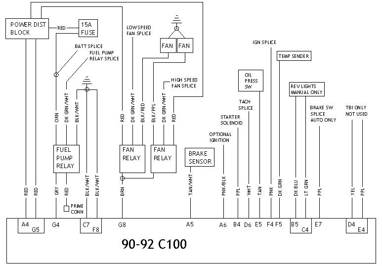
I just spent quite some time going through other peoples posts and some help from Pocket and others to come up with this diagram.
Can you guys please help me out and let me know if something looks wrong?
Is there an in-line fuse i need to include in the alternator wiring?
For the tach, i guess i just leave the wire from the harness tied up and i use the MSD 6AL output to go to the tach.
I am not sure what to do with the dual fans and the electric water pump. Where do i wire the blue + for the water pump so its only running when the car is running?
I already emailed the place that made the wiring for help but want to see if anyone else knows how i can wire the dual fans. I should the colors of the wires going to each of the relays. red and pink go to each and then one relay gets green and grey and the other gets blue and black.
All help is much appreciated. Do i need any other in-line fuses for anything?
I hope to get some input and fine tune this diagram and have it up for anyone using a new stand alone harness and aftermarket gauges as an alternative for anyone to comfortable with mating to harnesses together and cutting things up.
Thanks everyone. Pocket i hope you see this!
Last edited by SomeGuy25thZ; Apr 19, 2011 at 02:33 PM.

Re: LTX swap wiring diagram - stand along harness
Hmm, Id assume this is for your 92, so a 90-92 diagram will fit
Going down the list:
Anything wrong... not really. Some things can be simplified. First, you dont need a full blown stand alone for a 90-92 car because that would put a redundant fuseblock up front. You dont need a fuseblock hook-up and power dist block x2
No inline fuse per-say, but GM often put a fusible link at the end of the charge cable
Tach Id leave alone, direct connection to the C100. Let the MSD box see whats going on but let the PCM drive your tach
Fans have their own relays stock. A stand alone harness worth talking about will have a fuseblock with enough relays to support the engine and functions like fuel and fans. For the WP, add a slot to the stand alone's fuseblock and if there isnt room, use an inline fuse holder like whats stock on your fuel pump. In that case, tie into any IGN source large enough to support the draw such as the main IGN from C100 F4
For the fan relays, list color and relay pin location, such as 30, 86, 85, 87, 87a
Thread Starter
Senior Member
Joined: Sep 2007
Posts: 599
Likes: 1
From: Long Island, NY
Car: 1992 z28
Engine: 383 LT1 in the works
Transmission: T-56 in the works
Axle/Gears: 3.73 in the works
Re: LTX swap wiring diagram - stand along harness
I am sure things could be more simplified but because i didnt understand too much of the wiring i went with the stand alone harness.
Please bare with me as i know the more knowledgable people would have this setup running in no time.... This is how everything is setup and installed right now. I can easily change things around but at this point I'd like to get the stand alone harness i already have installed working with whatever else i need.
So the alternator can go straight to the power junction and have a battery to the power junction. this will reduce one large power cable for me. I showed it the way i did because some people said you have to have a separate power cable for alternator.
So no fuse needs to go to alternator wiring. thats fine. Is the brown wire i show from the alternator connector to G8 of C100 ok?
What is the problem with using the MSD box to supply the tach? I dont see why not to use the MSD box.
I have an aftermarket radiator/dual fan setup. this kit came with its own relays and wires into the coolant sensor directly but instead of using that the stand alone harness has the relays/fuses for a dual fan setup. the harness also has the relay and fuses needed to run the engine like you mention. the fuel feed++ line goes right to the pump which is easy. I just dont know how to power the fans off of this harness. Can i ground each fan and then tap into one of the wires coming out of hte relay as the signal to turn on the fan? just dont know which color is the signal wire.
I can wire the water pump to the iGN then. So the IGN connection is correct right where i have the IGN from C100 going to the harness. this basically means when i turn the key the IGN wire from C100 activates the harness IGN wire and all the necessary sensors/functions correct? so if i tap into this wire the water pump starts and stays running with the key but stop with the key off.
Now, will this leave the pump running if i leave the car in the "on" position but not running?
The wire into/out of the stand alone harness fan relays are as follows:
relay 1 - red, pink, green, and gray
relay 2 - red, pink, blue, and black
i imagine the blue on relay 2 is the activation wire to tie into(not sure) and dont know about relay 1.
Thread Starter
Senior Member
Joined: Sep 2007
Posts: 599
Likes: 1
From: Long Island, NY
Car: 1992 z28
Engine: 383 LT1 in the works
Transmission: T-56 in the works
Axle/Gears: 3.73 in the works
Re: LTX swap wiring diagram - stand alone harness
After some more reading i want to use a fuse for the alternator.. i actually havent seen one case where someone hasnt. I just dont know where to put a fuse and which kind to use (what rating?).
Anyone?
Is it on the main power cable that goes from battery to alt or is it on the small read wire that is in the alternator connector?
I also dont get how the power wires work. As the diagram shows i have the large power cable to the battery (or move to power junction with the battery connected to the power junction, which i need to power all other things) and then the red wire from the connector is at the junction too. is that right? why are there two power wires to basically the same place?
Member
Joined: Mar 2003
Posts: 152
Likes: 0
From: Richland, WA
Car: 1989 Trans Am
Engine: 94 383 LT-1
Transmission: Tremec 3550
Re: LTX swap wiring diagram - stand alone harness
one is the sensing wire the other is the batter charge wire. The voltage reg works by looking at voltage drop and tries to raise output to 14.9 (i think that is right voltage) but you get the idea.
Thread Starter
Senior Member
Joined: Sep 2007
Posts: 599
Likes: 1
From: Long Island, NY
Car: 1992 z28
Engine: 383 LT1 in the works
Transmission: T-56 in the works
Axle/Gears: 3.73 in the works
Re: LTX swap wiring diagram - stand alone harness
I updated the diagram. I am using a 100 amp mega fuse in the large alternator wire before the distribution block and the water pump will go to the IGN wire.
I'll put in all the grounds and hopefully run into no issues.
Still trying to figure out the fan hookup. If i cant get it i'll just use the wiring/relays that came with the fans and let them work on their own and have no issues with wiring.
I'll put in all the grounds and hopefully run into no issues.
Still trying to figure out the fan hookup. If i cant get it i'll just use the wiring/relays that came with the fans and let them work on their own and have no issues with wiring.
Re: LTX swap wiring diagram - stand along harness
I am sure things could be more simplified but because i didnt understand too much of the wiring i went with the stand alone harness.
Please bare with me as i know the more knowledgable people would have this setup running in no time.... This is how everything is setup and installed right now. I can easily change things around but at this point I'd like to get the stand alone harness i already have installed working with whatever else i need.
So the alternator can go straight to the power junction and have a battery to the power junction. this will reduce one large power cable for me. I showed it the way i did because some people said you have to have a separate power cable for alternator.
Yes
So no fuse needs to go to alternator wiring. thats fine. Is the brown wire i show from the alternator connector to G8 of C100 ok?
Yes
What is the problem with using the MSD box to supply the tach? I dont see why not to use the MSD box.
PCM is more accurate. Either should work
I have an aftermarket radiator/dual fan setup. this kit came with its own relays and wires into the coolant sensor directly but instead of using that the stand alone harness has the relays/fuses for a dual fan setup.
Old fan switch style. It will work, but Ive never fully trusted those thermal switches. The PCM resisters an exact coolant temp and controls the fans individually to maintain a desired temp. If the stand alone came with two fan relays pre-wired, then just connect the relay output wires to the fan 12v side and ground the other. If it just came with two wires from the PCM, you'll have to ID the correct pins on the relays set from the fan switch kit. Cut off the fan switch and wire them directly to the PCM
the harness also has the relay and fuses needed to run the engine like you mention. the fuel feed++ line goes right to the pump which is easy. I just dont know how to power the fans off of this harness. Can i ground each fan and then tap into one of the wires coming out of hte relay as the signal to turn on the fan? just dont know which color is the signal wire.
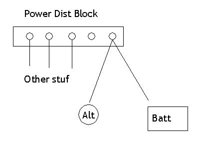
Basically, yes. Generally fans have red for power in 30, black/red power to fan motor 87, brown fused 12v ign 86, dk grn/wht trigger ground 85
Hears a basic diagram
I can wire the water pump to the iGN then. So the IGN connection is correct right where i have the IGN from C100 going to the harness. this basically means when i turn the key the IGN wire from C100 activates the harness IGN wire and all the necessary sensors/functions correct? so if i tap into this wire the water pump starts and stays running with the key but stop with the key off.
Right, but Id run an inline fuse to protect the pump. There isnt one in that wire
Now, will this leave the pump running if i leave the car in the "on" position but not running?
Yes
The wire into/out of the stand alone harness fan relays are as follows:
relay 1 - red, pink, green, and gray
relay 2 - red, pink, blue, and black
i imagine the blue on relay 2 is the activation wire to tie into(not sure) and dont know about relay 1.
Pop a relay off and look for pins 85,86. ID which is loose and which goes to a fuse/ground. For fans it should NOT be grounded
Please bare with me as i know the more knowledgable people would have this setup running in no time.... This is how everything is setup and installed right now. I can easily change things around but at this point I'd like to get the stand alone harness i already have installed working with whatever else i need.
So the alternator can go straight to the power junction and have a battery to the power junction. this will reduce one large power cable for me. I showed it the way i did because some people said you have to have a separate power cable for alternator.
Yes
So no fuse needs to go to alternator wiring. thats fine. Is the brown wire i show from the alternator connector to G8 of C100 ok?
Yes
What is the problem with using the MSD box to supply the tach? I dont see why not to use the MSD box.
PCM is more accurate. Either should work
I have an aftermarket radiator/dual fan setup. this kit came with its own relays and wires into the coolant sensor directly but instead of using that the stand alone harness has the relays/fuses for a dual fan setup.
Old fan switch style. It will work, but Ive never fully trusted those thermal switches. The PCM resisters an exact coolant temp and controls the fans individually to maintain a desired temp. If the stand alone came with two fan relays pre-wired, then just connect the relay output wires to the fan 12v side and ground the other. If it just came with two wires from the PCM, you'll have to ID the correct pins on the relays set from the fan switch kit. Cut off the fan switch and wire them directly to the PCM
the harness also has the relay and fuses needed to run the engine like you mention. the fuel feed++ line goes right to the pump which is easy. I just dont know how to power the fans off of this harness. Can i ground each fan and then tap into one of the wires coming out of hte relay as the signal to turn on the fan? just dont know which color is the signal wire.
Basically, yes. Generally fans have red for power in 30, black/red power to fan motor 87, brown fused 12v ign 86, dk grn/wht trigger ground 85
Hears a basic diagram
I can wire the water pump to the iGN then. So the IGN connection is correct right where i have the IGN from C100 going to the harness. this basically means when i turn the key the IGN wire from C100 activates the harness IGN wire and all the necessary sensors/functions correct? so if i tap into this wire the water pump starts and stays running with the key but stop with the key off.
Right, but Id run an inline fuse to protect the pump. There isnt one in that wire
Now, will this leave the pump running if i leave the car in the "on" position but not running?
Yes
The wire into/out of the stand alone harness fan relays are as follows:
relay 1 - red, pink, green, and gray
relay 2 - red, pink, blue, and black
i imagine the blue on relay 2 is the activation wire to tie into(not sure) and dont know about relay 1.
Pop a relay off and look for pins 85,86. ID which is loose and which goes to a fuse/ground. For fans it should NOT be grounded
After some more reading i want to use a fuse for the alternator.. i actually havent seen one case where someone hasnt. I just dont know where to put a fuse and which kind to use (what rating?).
Fusible links are supposed to be 1/2 the gauge of the wire they're protecting
Anyone?
Is it on the main power cable that goes from battery to alt or is it on the small read wire that is in the alternator connector?
Your main battery cable goes from the battery to starter. The small leg of it goes to the power dist block. Alt is a single cable going from the alt output lug to the power dist block. Harness 12v cables simply join at the power dist block
I also dont get how the power wires work. As the diagram shows i have the large power cable to the battery (or move to power junction with the battery connected to the power junction, which i need to power all other things) and then the red wire from the connector is at the junction too. is that right? why are there two power wires to basically the same place?
Draw power from the same place for simplicity. In the alt's case, it feeds new 12v power into the system
Trending Topics
Thread Starter
Senior Member
Joined: Sep 2007
Posts: 599
Likes: 1
From: Long Island, NY
Car: 1992 z28
Engine: 383 LT1 in the works
Transmission: T-56 in the works
Axle/Gears: 3.73 in the works
Re: LTX swap wiring diagram - stand alone harness
Pocket - cant tell you how awesome you are! thanks a lot.
Last questions i promise lol...
What fuse would be good for the water pump (10, 15, 20, ... amp?). I dont like how the pump will be running in the 'on' position. Maybe I can run an override switch to prevent this but then its just another thing i have to remember to turn on so i dont overheat by accident!
I think i have the fan wiring down. Thanks for making all this clear.
Wiring from the PCM for the tach is easy enough, i'll stick with that.
I put in ground cables today:
- driver heat to frame rail
- driver side block to frame
- passenger side block to metal bracket by radiator
Should i run any others to be safe?
Thanks again pocket. Hopefully my next LT1 swap goes easier lol

Thread
Thread Starter
Forum
Replies
Last Post