When you click on links to various merchants on this site and make a purchase, this can result in this site earning a commission. Affiliate programs and affiliations include, but are not limited to, the eBay Partner Network.
Tech / General EngineIs your car making a strange sound or won't start? Thinking of adding power with a new combination? Need other technical information or engine specific advice? Don't see another board for your problem? Post it here!
I've been reading a bunch of information on this car - 85 LG4 Sport Coupe - I'm working on getting it in better repair for a family member.
The car has been butchered by several different shops and has had a complete engine swap at least once in its life.
Currently it still has an electronic distributor with no vacuum advance, and a CCC Quadrajet. The check engine light is on but won't flash any codes.
Underhood is a disaster of disconnected electrical, missing vacuum lines, lines going to weird places. The AIR pump is gone. the EGR valve's vacuum line is missing, the EFE valve's vacuum line is missing. The throttle kicker is missing off the carburetor, the choke plate is missing. The air manifold pipes are still present but has a hole at the check valve that will require replacing or possibly welding up.
Obviously the car isn't running right but does run better than you'd expect. I think the best course of action is to finish getting rid of all the computer components, and switching to a non-CCC quadrajet and vacuum advance distributor. At least I will be able to tune it. Then finish taking off all the remaining unused items. I can't imagine being able to cost effectively get this system all put back in place the way it is supposed to be.
Example being trying to get the EGR system working will be a rabbit hole of running a new vacuum line to a solenoid that probably isn't working and requiring replacement, the EGR valve itself is probably stuck plus the computer missing so many other system inputs probably won't activate the solenoid anyways... and that just the EGR, I expect similar situations with the EFE, AIR, Cruise Control, etc.
I want to take the web of line and wires out - and put back the bare necessities so that heat and air works, gauges, cruise control, wipers, etc. all work.
In the end this engines days are numbered, a clean simple 350 is the end goal but I have to get this car running right and in good tune as it is for the least amount of $$$. Any thoughts on how to proceed are appreciated.
Vacuum line is very cheap. I'd replace all those and eliminate all the "probablies" so you can make a determination of whether it would be cheaper to replace the known inoperable items or switch to an analog setup.
I second repairing all the vacuum lines first. Vacuum line is cheap and you can reuse it if you wind up swapping the motor or going non-CCC. You'll need some vacuum line regardless of what you do and you might as well plan to replace all of it while you're in there.
From what you described it sounds like the big ticket item is the AIR pump. I don't think they're available new but there are some refurbished on eBay. I believe it's PN 7836061. Of course you'll need the mounting hardware, pulley, the little section of hard tubing, solenoids, etc (if they're not already in there).
I could be wrong since I haven't worked on an 85, but I don't think the CEL will come on without a computer present and connected. Don't know if that means the computer is still usable though.
Do you have emissions testing where you live? If not, My opinion would be that since so much has already been butchered by other yahoos, to remove all that crap along with the entire ECM wire harness, and install a non-CCC carb and a vacuum advance distributor...
I agree with replacing vacuum lines and trying to get back to a baseline first. The computer carb and distributor are pretty reliable and have good drivability as long as it�s working correctly. It�s really not all that complicated either.
The missing AIR system won�t affect how it runs and the computer won�t know it�s not there. Just make sure to cap the connections at the exhaust manifolds and converter.
It will run fine without the EGR. Might throw a check engine light if the EGR solonoid isn�t connected, but you could leave the solonoid in place and remove the valve and put a block off plate there and cap the vacuum lines. This can be put back later if desired.
The EFE valve at the exhaust manifold can be locked open. It helps with cold start drivesbility, but it will still run well without it. This can also be reactivated later if desired.
The computer carb system doesn�t really need much to run. A lot of these peripherals are there for emissions and aiding in cold start driveability, but the computer doesn�t know if they are there or not. Most of these things can be disabled or eliminated to help with diagnostics and to get it running well, and then put back in place if you wish.
After getting the vacuum lines squared away, see if you can pull any codes from the ECM and go from there.
I think I'm making some headway making sense of everything in the engine compartment. I'll need to spend some time with a wiring and vacuum diagram to verify what is and isn't connected.
The car definitely smells like its running too rich, and has a miss at idle. Drinks gas - the little I've driven it, probably 10mpg or less.
Still can't get any codes to flash when the test terminal is grounded.
The throttle kicker is doing something - when I plug it in the solenoid activates and pushes the throttle open - too much. I scraped on the wire to determine the color because it looks black, but I think it is dark blue.
TCC is not hooked up, may not even have provisions in the transmission for it. I found the wires cut at the transmission housing.
AIR system appears gone in its entirety, the manifolds are plugged.
I'll need to trace where the vacuum line on the TVS goes, because it doesn't go to the actuator.
There is a tube at the front of the carburetor on the base on the right hand side below and to the left of the TPS - don't know what connects to it. Maybe the canister control valve? But all its line already go somewhere else, maybe incorrectly.
I found a diagram that I was able to reroute some items and match up to pretty closely. This took care of the port on the front. One line is supposed to run to the air cleaner, but I don�t know if I connected it to the right spot. One port on the carb left unaccounted for; at the rear on top in the enter going straight out the back?
Electrically on the passenger side are two two wire plugs, I�m assuming for the AIR so I�m not worried about those. On the driver side a two wire plug presumably for the A/C compressor the dark blue wire and a dark green, not sure about the dark green?
I don�t hear any clicking under the hood with key off, maybe a dead M/C solenoid and still no codes�
Dark green wire must go to another temperature switch, I didn't expect there to be two...
Aside from the mystery port on the rear of the carburetor, up high right under the air cleaner. I think it will be as close to the way its supposed to be to start diagnosing.
Update: Finally got the ECM off its 20 year bender - sobered up and trying to work things out with the carburetor at least.
After diagnosing a no blink check engine light as a burnt up ECM and replacing it with a salvage unit - got really lucky on that one - the computer is telling the carburetor to do stuff... I think it is spasing out the mixture solenoid, because its clicking like crazy now. I put 20 miles on it and no new check engine light.
Meanwhile also put in new plugs and wires. Prior to the ECM being sorted out it idled pretty good, slight miss every now and then. Now with the ECM working there is a pretty good sputter at idle I also had to dial the idle screw up, I think the mixture solenoid leaning out the mixture needed the screw to be turned in some.
Also, took forever to find the engine light driver module. It was all the way over on the driver side, above the convenience center.
I think I'm going to do a rebuild on the carburetor, along with a new distributor cap and rotor. Car is definitely running worse than before getting the ECM working. Since the only thing different is its now screwing with the carburetor, its not up to task.
The cap and rotor are just worn out after inspection.
In normal operation of the CCC system and mixture control (MC) solenoid on the QuadraJet, the solenoid should operate almost constantly, usually about 4-6 times a second (Hertz). The duration of the pulses from the ECM controls the mixture. There is an adjustment for that as well, and it is heavily dependent upon a good signal from the TPS (inside the carb body adjacent to the accelerator pump) and a signal from an good oxygen sensor. That's all in the carburetor service instructions.
The idle kicker solenoid is also adjustable. That should also be in the carb service directions. The choke pull-off (I hope you find a choke plate) is also an adjustment.
I done screwed up, I didn�t remember the turns on the lean mixture screw during disassembly, so I�m sure my rebuild results won�t be pretty. Of course this isn�t a virgin core either, all the plugs were gone.
Remove the air cleaner and cap any vacuum lines that were disconnected;
Unplug the Throttle Position Sensor and enrichment solenoid connectors;
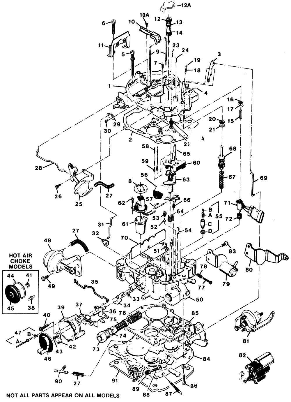
Remove the choke pull-off actuator and linkage rod (25 & 28);
Remove the secondary metering rod cam follower (10) and metering rods (9);
Remove the choke lever screw and lever, and the linkage rod (29, 30, & 31);
Remove the air horn screws (5, 6, & 7) and the two front carburetor to intake bolts;
Carefully lift the air horn (1) off the carburetor body. As you do, pivot the air horn to allow the accelerator pump linkage rod to be removed from the top lever (3, 69);
Hold down the float hinge pin (57) and simultaneously hold the front end of the float (56) closed against the inlet needle and seat (55), to raise the float to its maximum position. Verify correct float level by measuring the rear edge of the float to the top of the carburetor body with no gasket in place. Gently bend the float tab to raise or lower this setting to the specification;
Replace the gasket and reassemble the carburetor, being careful to properly align the metering rods, pickup tubes, and TPS actuator plunger;
Reconnect the hoses and electrical connectors;
TPS ADJUSTMENT
Start engine and allow it to reach normal operating temperature;
Set engine timing at the specified RPM;
Set base idle speed with the A/C off and idle speed solenoid disconnected;
Turn off the engine;
Insert the probes of a digital voltmeter in terminals �B' and �C' on the TPS connector (center and bottom terminals). You may have to insert a paper clip or similar object into the rear of the connector to make contact;
Turn on the ignition but do not start the engine. Read the voltage of the TPS. Remove the top plug (19) and adjust the TPS screw (18) to obtain a reading of 0.48VDC across the terminals.
NOTE - If your meter probes are reversed, the reading will be -0.48VDC. The important factor is the number.
Replace the hole plug in the adjustment screw hole when the position is set.
MC SOLENOID ADJUSTMENT
Connect a dwell meter or oscilloscope probe to terminal �B' on the enrichment solenoid connector;
Start the engine and allow it to reach normal operating temperature. Start the engine and reset the base idle if necessary. The dwell meter reading should vary while this is occurring, or the oscilloscope square wave frequency (pulse length) should vary;
Set the parking brake, block the drive wheels, and place the transmission in DRIVE for an automatic car, NEUTRAL for a manual car;
The dwell meter reading should fluctuate between 10� and 50� on the 6 cylinder scale, the oscilloscope should indicate a 15-85% duty cycle. Adjust the idle air bleed valve screw (12) in 1/8th turn increments to obtain a dwell reading between 25�-35�, The optimum setting is 30� (50% duty cycle), so get as close to this as possible. Adjust the screw only a little at a time and allow the system to react between adjustments;
If the desired reading is not attainable through this method, the idle mixture screws will have to be adjusted (87). This will require removal of the carburetor and cutting the throttle body away around the steel plugs. Then reinstall and adjust the idle mixture screws evenly , then adjusting the idle air bleed screw as described above to obtain the correct readings.
A "dwell" meter is basically a duty cycle meter that is graduated on degrees of distributor rotation for an engine. In Kettering (breaker point) ignition system terms, the duty cycle is the amount of time that the circuit is on (points closed) versus the amount of time the circuit is off (points open). The meter face is graduated in degrees of distributor rotation. A point dwell angle of 30� on a V-8 engine is basically a 66% duty cycle, or ON time versus OFF time. One cylinder fires every 45� of distributor rotation (90� of crank rotation), so if the points are closed for 30� of that time, they are open for 15� of that interval. 30� � 45� = 2/3, or 66%.
A six cylinder engine is similar, but one cylinder fires every 60� of distributor rotation (120� of crank rotation). Typical specs for ignition point dwell on a six cylinder are 33�, and on a four cylinder engine 40� is common.
In terms of the mixture control solenoid on your carburetor, it is basically the same thing. The dwell meter is used to determine the amount of time the MC solenoid is ON versus OFF, or duty cycle. Since most automotive technicians have (or had) a dwell meter, the specification is presented in terms of dwell degrees. In reality, the measurement is the duty cycle percentage of the solenoid, but the common dwell meter is not graduated in those terms. Remember that 30� on the "V-8" setting on your dwell meter really means 66% duty cycle, and 45� would equal a 100% duty cycle.
Typical instructions for setting the solenoid are to set the meter on the six cylinder scale and adjust the "dwell" to an optimum of 30�, or in reality a 50% duty cycle. This means the solenoid is ON an equal amount of time that it is OFF. This is the optimum setting for fullest range of control by the MC solenoid.
If you don�t have a dwell meter, but do have an oscilloscope or better quality DMM with a duty cycle scale, just set the MC solenoid for 50% or as closely as you can get it. The typical instructions indicate that any reading between 10� and 50� and varying is acceptable (15-85% duty cycle), but �acceptable� isn�t good enough for most of us, or we wouldn�t be here.
Once you have it running correctly in stock form, you can begin the power tweaking and tuning.
Remove the air cleaner and cap any vacuum lines that were disconnected;
Unplug the Throttle Position Sensor and enrichment solenoid connectors;
Remove the choke pull-off actuator and linkage rod (25 & 28);
Remove the secondary metering rod cam follower (10) and metering rods (9);
Remove the choke lever screw and lever, and the linkage rod (29, 30, & 31);
Remove the air horn screws (5, 6, & 7) and the two front carburetor to intake bolts;
Carefully lift the air horn (1) off the carburetor body. As you do, pivot the air horn to allow the accelerator pump linkage rod to be removed from the top lever (3, 69);
Hold down the float hinge pin (57) and simultaneously hold the front end of the float (56) closed against the inlet needle and seat (55), to raise the float to its maximum position. Verify correct float level by measuring the rear edge of the float to the top of the carburetor body with no gasket in place. Gently bend the float tab to raise or lower this setting to the specification;
Replace the gasket and reassemble the carburetor, being careful to properly align the metering rods, pickup tubes, and TPS actuator plunger;
Reconnect the hoses and electrical connectors;
TPS ADJUSTMENT
Start engine and allow it to reach normal operating temperature;
Set engine timing at the specified RPM;
Set base idle speed with the A/C off and idle speed solenoid disconnected;
Turn off the engine;
Insert the probes of a digital voltmeter in terminals �B' and �C' on the TPS connector (center and bottom terminals). You may have to insert a paper clip or similar object into the rear of the connector to make contact;
Turn on the ignition but do not start the engine. Read the voltage of the TPS. Remove the top plug (19) and adjust the TPS screw (18) to obtain a reading of 0.48VDC across the terminals.
NOTE - If your meter probes are reversed, the reading will be -0.48VDC. The important factor is the number.
Replace the hole plug in the adjustment screw hole when the position is set.
MC SOLENOID ADJUSTMENT
Connect a dwell meter or oscilloscope probe to terminal �B' on the enrichment solenoid connector;
Start the engine and allow it to reach normal operating temperature. Start the engine and reset the base idle if necessary. The dwell meter reading should vary while this is occurring, or the oscilloscope square wave frequency (pulse length) should vary;
Set the parking brake, block the drive wheels, and place the transmission in DRIVE for an automatic car, NEUTRAL for a manual car;
The dwell meter reading should fluctuate between 10� and 50� on the 6 cylinder scale, the oscilloscope should indicate a 15-85% duty cycle. Adjust the idle air bleed valve screw (12) in 1/8th turn increments to obtain a dwell reading between 25�-35�, The optimum setting is 30� (50% duty cycle), so get as close to this as possible. Adjust the screw only a little at a time and allow the system to react between adjustments;
If the desired reading is not attainable through this method, the idle mixture screws will have to be adjusted (87). This will require removal of the carburetor and cutting the throttle body away around the steel plugs. Then reinstall and adjust the idle mixture screws evenly , then adjusting the idle air bleed screw as described above to obtain the correct readings.
A "dwell" meter is basically a duty cycle meter that is graduated on degrees of distributor rotation for an engine. In Kettering (breaker point) ignition system terms, the duty cycle is the amount of time that the circuit is on (points closed) versus the amount of time the circuit is off (points open). The meter face is graduated in degrees of distributor rotation. A point dwell angle of 30� on a V-8 engine is basically a 66% duty cycle, or ON time versus OFF time. One cylinder fires every 45� of distributor rotation (90� of crank rotation), so if the points are closed for 30� of that time, they are open for 15� of that interval. 30� � 45� = 2/3, or 66%.
A six cylinder engine is similar, but one cylinder fires every 60� of distributor rotation (120� of crank rotation). Typical specs for ignition point dwell on a six cylinder are 33�, and on a four cylinder engine 40� is common.
In terms of the mixture control solenoid on your carburetor, it is basically the same thing. The dwell meter is used to determine the amount of time the MC solenoid is ON versus OFF, or duty cycle. Since most automotive technicians have (or had) a dwell meter, the specification is presented in terms of dwell degrees. In reality, the measurement is the duty cycle percentage of the solenoid, but the common dwell meter is not graduated in those terms. Remember that 30� on the "V-8" setting on your dwell meter really means 66% duty cycle, and 45� would equal a 100% duty cycle.
Typical instructions for setting the solenoid are to set the meter on the six cylinder scale and adjust the "dwell" to an optimum of 30�, or in reality a 50% duty cycle. This means the solenoid is ON an equal amount of time that it is OFF. This is the optimum setting for fullest range of control by the MC solenoid.
If you don�t have a dwell meter, but do have an oscilloscope or better quality DMM with a duty cycle scale, just set the MC solenoid for 50% or as closely as you can get it. The typical instructions indicate that any reading between 10� and 50� and varying is acceptable (15-85% duty cycle), but �acceptable� isn�t good enough for most of us, or we wouldn�t be here.
Once you have it running correctly in stock form, you can begin the power tweaking and tuning.
Thanks for all that information, I haven't come across much of it yet.
I was intending to set the lean mixture stop using some sort of something trimmed down to the 1.304" spec. Then set the rich for the 4/32" travel. Lastly the idle air thing... I think that should at least get me to a baseline.
Like you said get it running - then tune it.
Got the carburetor bench adjusted, back on the car with the following results.
Still messy idle, will occasionally stall.
Runs ok at medium throttle input.
New problem, no WOT. At about 3/4 pedal power plummets and begins decelerating if you are already up to speed. If you are accelerating from a stop it has no acceleration. No changes to fuel delivery, so I�ve got something put back together wrong.
System Performance Check shows fixed dwell at 30 degrees, and leads to an oxygen sensor problem. This might help the idle, but doesn�t explain the new WOT problem. Thoughts?
The easy items to check without disassembling the cover are secondary operation and M/C solenoid travel. If the secondaries are connected and operating, are the secondary metering rods connected to the hanger? Is the hanger moving upward as the secondary AV opens?
Since the E4ME does not have the old-style power enrichment valve for the primaries, is the rich stop adjusted far enough up to allow the solenoid enough travel for rich operation?
If those are correct, what is the current float level adjustment?
M/C solenoid travel was checked on the bench, a hair over 4/32”.
Secondaries are connected, metering rods in the hangers, the hanger moves up with the air valve.
I presume the rich stop is high enough, based on the travel amount.
Float level is 11/32.
As a test I unplugged M/C solenoid for full rich, with no change in WOT, this eliminates the solenoid and TPS. I can’t think of what else would cause a fueling issue.
Last edited by asilverblazer; Apr 17, 2022 at 10:36 PM.
I've been thinking about this problem with WOT performance. The only changes were made in the carburetor via a rebuild kit. Only a few possibilities exist:
1. The secondary throttle blades aren't opening.
Not likely, because the linkages are connected and operate smoothly. The secondary lock out is also not locking out the secondary's.
2. The air valve isn't opening.
I don't think the vacuum break is preventing this. The engine is running healthy enough on what seems to be the main metering circuit that sufficient vacuum to pull open the valve should be present.
3. No fuel from the secondary discharge.
Not sure what could prevent this, but I can manually operate the air valve and it operates freely and lifts the rods too.
4. TPS
Maybe the TPS has a dead spot at about 3/4 travel throwing off the ECM/timing or something... Its a very distinct position in the pedal where this problem occurs that makes me think down these lines, the ECM isn't supposed to do anything to the carburetor at WOT, does it control timing though? If the TPS is telling the ECM that it isn't at WOT while the pedal has all the blades open, and the carburetor is pouring all the fuel in, would the ECM be retarding or advancing timing because it thinks it should be coasting decelerating or the like?
Failure of a critical input (like the TPS) generally shifts the ECM into backup fuel and spark mode. That would be a situation where the MC solenoid would default to rich and the timing would default to base timing.
It would be easy enough to test the TPS in place by monitoring the voltage as the throttle is moved smoothly from idle to WOT, key on, engine off, of course.
Ugh, another set back. The junkyard ECM died. Problems are increasing rather than decreasing, so frustrating, I know why everyone abandons this and goes to mechanical carburetor and distributor. I’m about ready to. Need to see what I can do for either repairing one of these ECMs or getting a replacement.
Long story short, I repaired one of my two ECMs by pulling a chip from one and soldering it on to the other.
Back working - at least enough to do some more testing.
Dwell is varying both at idle and 3000 rpms, generally with in specified range. It is messy though, I can see, feel and hear the stumbling misses. Shows up in the dwell too.
Leading to next step is carburetor calibration.
Also, got a TPS code 23, so hopefully a new sensor will fix that and with a bit of luck, the WOT problem.
If the dwell is responding with changes in O2 sensor voltages, AND doesn't peg full rich or full lean, then it's close enough in adjustment not to cause the issues you seem to be experiencing.
I'd focus on the ignition system, plugs/wires/cap/rotor, maybe even a new distributor if suspect. a mis-fire will really screw up the ECM's conception of the actual state of nature.
a balance test might prove useful. get it idling fairly smoothly with the MCS dis-connected and pull one plug wire at a time. dis-connecting the MCS will prevent it from changing dwell due to O2 changes from a miss (right bank only) but will cause it to run full rich so don't run it too long this way.
I can't tell if if pegs one direction or the other, but there are some noticeable swings in it that track with the actual stumbling miss in the car.
Plugs, wires, cap and rotor are all new.
I think I have two separate issues right now, the idle miss and the WOT not working. The idle problem, I'm thinking could be helped by carburetor calibration, but might be deeper, the car may have rolled over the odometer to have 192,000 miles. Maybe a slack timing chain? Vacuum gauge shows low vacuum (2 in the green on my gauge) but fairly steady except for the miss.
WOT... I'm not sure on, I think the TPS is messing it up somehow, I think its signal goes bad at a certain point in the travel, making the ECM cut fuel or timing when it shouldn't. If not the TPS something physical in the carburetor is either stopping or preventing the secondary's fuel flow or plates from opening. In either case it is a very fine and distinct point in the pedal position that the problem presents itself; it didn't have this problem until I pulled the carburetor cleaned it up and replaced gaskets, check ball, needle & seat, etc. I even put the old needle and seat back in to make sure they weren't hampering fuel flow.
Instead of a color, what is the indication on the vacuum gauge at idle (in inches of Mercury) ? 15-19 is pretty normal, depending upon the temperature, elevation, and idle RPM.
sure sounds like you're fighting a miss and the carburetor system is just trying to compensate, of course I'm not looking at it.
TPS has virtually no affect on WOT.
verify the choke pull off works by unplugging the vac line, holding your finger over the nipple with the plunger in. as you release your finger the plunger should extend.
try setting you air valve tension to as weak as you can for them to stay closed. you'll note a bog but it should stumble past that and go.
the little cam that lifts the secondary rods up as the air valve opens has been known to crumble to dust. check it.
could always have a pickup tube that fell out of the air horn, too.
Instead of a color, what is the indication on the vacuum gauge at idle (in inches of Mercury) ? 15-19 is pretty normal, depending upon the temperature, elevation, and idle RPM.
I couldn't remember the numbers on my gauge... but I found a picture from another project. 17-18 With no wild fluctuations maybe 1 at misses.
sure sounds like you're fighting a miss and the carburetor system is just trying to compensate, of course I'm not looking at it.
TPS has virtually no affect on WOT.
verify the choke pull off works by unplugging the vac line, holding your finger over the nipple with the plunger in. as you release your finger the plunger should extend.
try setting you air valve tension to as weak as you can for them to stay closed. you'll note a bog but it should stumble past that and go.
the little cam that lifts the secondary rods up as the air valve opens has been known to crumble to dust. check it.
could always have a pickup tube that fell out of the air horn, too.
I probably am fighting a miss. I tightened up the idle air bleed and it helped some. I don't think that is the solution though. Once I get the new computer installed I'll be more confident with tuning that.
I think the choke pull off is working, but I'll confirm it using your method.
No adjustments have been made to the air door tension,
The cam is still in place and working.
About those pick up tubes though. I pulled the airhorn off last night. One of the pick up tubes stayed in the carburetor instead of coming up with the air horn. I put it back in, no change.
Thanks for all the help so far gentlemen!
Recap:
The car does not have the original engine. Lots of wiring and vacuum lines were unhooked, ran incorrectly, etc. Car has had a miss, and smelled really rich. Generally in poor repair outside of regular oil changes. Original ECM was bad, number 7 plug wire unhooked, missing choke plate. Semi-removed AIR, no cats, no TCC (or at least the wires to it have been cut).
Repairs:
Remove the AIR tubes from the manifolds and capped them. Reconnected and re routed vacuum lines, plugged in everything unhooked. Replaced ECM with a different one, with different problems. New spark plugs, wires, cap, rotor, fuel pump.
Prior to rebuilding the carburetor the car ran pretty good except for the miss, WOT throttle worked and had surprisingly good power. So, I'm pretty sure something is messed up in the carburetor.
When the computers have worked at various stages I've gotten codes 13, 23, 54. In addition to failure to blink codes at all. No codes blinking and 54, lead to 2 bad ECMs, confirmed by opening them up and finding burnt out chips.
Got the new ECM in, no codes - good.
Still misses, still no WOT.
I pulled plug wires one at a time and they all seemed to make it equally worse, I might try that again with a tachometer or vacuum gauge to see if I can see a change that I can�t hear.
I�m going to inspect the fuel line and filter in the carburetor again, fuel delivery makes sense with the symptoms at WOT, I hesitate because no changes were made that would have altered the fuel delivery, maybe moving the line around knocked some build up loose.
I threw a timing light on it, lot of good it did, I couldn�t find a pointer, then it got dark.
If nothing else, I�m going to start capping vacuum ports on the carburetor, looking for a leak, maybe a compression check too.
when setting dwell it's always a good idea to cap EVERY vacuum port first. set dwell then re-connect each and look for a change that may indicate a vac leak.
if this distributor is original or of unknown age and condition, consider replacing it. not very expensive for peace of mind.
The power balance test (pulling one plug wire at a time) seemed to indicate that all holes are firing normally and making power. A compression test at this point could be useless.
With the EST active, the timing mark could be out of sight. I've seen engines at full temperature with well over 20� advance at idle under EST control, and that can be normal. Pulling the timing connector at the distributor to set base timing is about as good as it gets until it is running relatively normally, whereupon experimenting with timing can commence.
Adding a filter in the fuel line ahead of the carburetor is completely acceptable.
I found a couple things this evening, with most vacuum ports capped:
When in diagnostic mode I can get dwell to behave correctly, varying around 30 degrees. It requires screwing the idle air valve all the way in and it flashes code 13 while in diagnostic mode.
Not in diagnostic mode, with oxygen sensor connected dwell raises to upper 40s to low 50s engine will occasionally stall, ground the wire from sensor to engine dwell drops down to about 2. With the wire to ECM grounded voltage on the sensor is about 0.78.
It seems that the ECM is reacting to the oxygen sensor input. Getting it dialed in to precisely 40-50� dwell is not critical. The important thing (for now) is that the system is actively attempting to control mixture
What is the TPS sensor voltage at hot idle?
Is the float level still near 11/32" down?
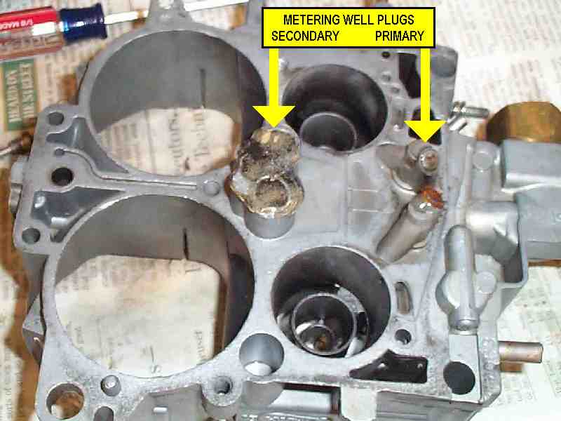
Also, are the metering well plugs (on the bottom of the carb body) sealed? Those tend to leak without some sealant applied over the Welch plugs, and can really kill the mixture control.
It seems that the ECM is reacting to the oxygen sensor input. Getting it dialed in to precisely 40-50� dwell is not critical. The important thing (for now) is that the system is actively attempting to control mixture
What is the TPS sensor voltage at hot idle?
Is the float level still near 11/32" down?
Also, are the metering well plugs (on the bottom of the carb body) sealed? Those tend to leak without some sealant applied over the Welch plugs, and can really kill the mixture control.
I got it to run near 30 degrees dwell, monitoring oxygen sensor, it would fluctuate and dwell would follow it. Still misses, still no WOT.
I�ll need to confirm TPS voltage, it was a smidge high. The well plugs were ok when the carburetor was apart. Float should be 11/32� down, I haven�t found the measurement from the top of the air horn down (on vehicle check). Idle air bleed is in nearly bottomed out.
After starting the engine and grounding test terminal still gives code 13, but I can monitor it running and it seems fine. Voltage at ECM matches what�s at the sensor.
I think I�m going to start ignition diagnosis - or something else, since carburetor seems to be functioning properly.
Car won�t start in neutral, could that switch be causing problems?
At idle the timing mark on the balancer is at about 8 o’clock visible only visible looking under the alternator and water pump way advanced or retarded of the pointer.
Diagnostic mode brings timing up almost to the pointer 11 o’clock.
When not in diagnostic mode timing advances to about 10 o’clock when reving the engine .
Last edited by asilverblazer; Apr 24, 2022 at 07:26 PM.
the 0 degree mark is at approximately 11 o'clock. This should be near (+0-4) your base timing, set with the ESC disconnected.
the timing mark on the balancer should advance to around the 12 o'clock position at idle with the ESC connnected.
the other direction is retarded.
I don't think the system can retard timing below the base setting.
your timing mark on the balancer could very well be wrong, in the wrong spot. they can slip and otherwise fail.
but the behavior I infer you're describing doesn't make sense.
I was picturing the sawtooth indicator at 12 o'clock - I'll readjust my description below to account for that. The mark I see on the balancer is a solid line that goes across the balancer. That mark never moves far enough clockwise to get to the sawtooth indicator.
I'm standing at the front of the engine looking at it as a face of a clock, and I can't remember which direction is advancing or retarding. I think clockwise is retarding timing and counter clockwise is advancing timing.
At idle the timing mark on the balancer is at about 7 o’clock only visible from the passenger side looking under the alternator and water pump way counter clockwise of the pointer. Advanced of the pointer?
Diagnostic mode moves timing (clockwise) up almost to the pointer 10 o’clock. Retards timing?
When not in diagnostic mode timing moves from 7 o'clock to about 9 o’clock when revving the engine maybe 20 to 30 degrees. That would be retarding the timing right?
If the mark I am looking at is not the right mark and all these indications are advanced on my clock face it seems like the timing isn't far off. (There might have been a faint dot I saw on the balancer at about 10 o'clock just ahead of the pointer, but I couldn't see it nearly as well as the line, so I went with the line.)
Connecting or disconnecting the ESC has no change on timing.
I educated myself a bit... At idle with everything connected test terminal not grounded. Timing is WAY advanced nowhere near the scale. 60 degrees sounds wrong but if from the big valley to the end of the timing scale is 15 degrees give or take, all the way to where the mark is has to be a bunch more than 30 degrees.
With the test terminal grounded at idle timing might be closer to 30 degrees advanced (and the engine is running better too.)
When not in diagnostic mode revving the engine retards timing from 60 degree mark at idle to about 40 to 30 degrees.
Connecting or disconnecting the ESC module to the right of the brake booster has no change on timing.
the timing mark will appear to move clockwise when it advances, from a general direction pointing towards the car's driver side towards the hood.
the engine spins counterclockwise (reference point in the driver's seat). For the ignition to advance it must fire EARLIER in the firing order so the mark will appear to move clockwise as it advances from this reference point.
with the EST disconnected (to set base timing) the mark should roughly line up with the big valley on the marker. Once the EST is re-connected the ECM commands its advance and it should be WAY off the marker at all times (except limp home mode). At idle maybe 20+ degrees.
Again though, the line can shift on a balancer as the balancer fails. and the little marker guage thing on the timing cover could be the wrong one for the balancer (there are two different types that can be inadvertently interchanged).
A little white paint in the line/groove on the balancer can help you see it.
I assume your diagnostic mode is the mode that disengages knock sensor feedback? that mode won't affect timing advance, just let it ignore the KS.
with the EST disconnected (to set base timing) the mark should roughly line up with the big valley on the marker. Once the EST is re-connected the ECM commands its advance and it should be WAY off the marker at all times (except limp home mode). At idle maybe 20+ degrees.
Again though, the line can shift on a balancer as the balancer fails. and the little marker gauge thing on the timing cover could be the wrong one for the balancer (there are two different types that can be inadvertently interchanged).
I assume your diagnostic mode is the mode that disengages knock sensor feedback? that mode won't affect timing advance, just let it ignore the KS.
I have not disconnected the EST, only the ESC.
I need to find the tan with black tracer wire to unplug, disconnecting the EST right? I can't find timing check instructions in the service manual, only to check the under hood information label, which is gone.
I don't need more variables in this mess, but it could be a failing balancer, or the wrong gauge too.
I don't know what all the diagnostic mode does except fixed timing... Chart C-5 is ran without the test terminal grounded. Knocking on the engine near the knock sensor does nothing to RPM's and disconnecting the ESC does not alter the timing. The end of the chart results is "replace ESC controller".
Diagnostic circuit check passes, system performance check passes except flashing code 13 while running the check.
disconnecting the four wire connector to the base of the distributor will cause the ECM to lose control of the timing. the timing will retard and the engine may very well 'die'. the throttle kicker relay should extend to help it keep running, although it still may be on the edge of being able to idle at that reduced timing. you may have to bump up the curb idle adjustment some to keep it running. Disconnected the distributor will operate on the built in 'limp home' timing within the ignition control module. note that this rudimentary timing map should have a bump in advance around 1500 ish rpm. so if you open your throttle too much you run the risk of adjusting base from the wrong starting point.
Anyway I don't really think your miss is caused by maladjusted timing. if it was idling fine and responding to changes in mixture by varying dwell it should be close enough to troubleshoot your miss. if the dwell was responding directly to any miss then you've narrowed it down to the left bank, where the O2 sensor is.
if the miss is more evident under load, at higher cylinder pressure conditions, then it points towards a weak spark which fails when the mixture is harder to burn. it's relatively easy to light the fire under no load, idle conditions.
I think I will check the timing to cover my bases which I am running out of.
I know there is something wrong somewhere I just haven't found it yet. Retarding the timing at idle improved the idle miss and with everything connected it retards timing (the mark on the balancer moves from the passenger side towards the driver side) when revving the engine. This is the opposite of what I would expect.
I cannot detect the miss while driving except at the very slowest of speeds and throttle input (essentially the idle circuit in the carburetor). Above idle to say 85% throttle the car runs fine, maybe a little weak at the upper RPM's. At the 85% throttle it falls on its nose, power stops, acceleration stops, RPM's just kind of hang there as it loses speed, eventually it might downshift as enough speed is lost and the greater mechanical advantage may let it pick up speed very slightly. Back out of the throttle to 84% and power and acceleration pick right back up like nothing in the world. No bucking, no back firing, no shaking - just no power.
I think the distributor doesn't need adjustment like you say, something else is doing this, the ESC? if it were a cheaper part I'd change it but $100 is a big pill to swallow when I'm not certain.
Timing with the EST unplugged, I found the right one, was a bit too advanced from spec. It was about 15-20 degrees BTDC, I dialed it back to 6 degrees BTDC.
Idles WAY better may or may not have an actual miss now vs just a sputtery sounding exhaust. Sitting in the car in gear you don�t notice a miss, just what some might describe as a coarse carbureted V8.
No codes, dwell is on the money, STILL same WOT problem.
Should I be able to get the air break to open letting the vacuum pull open the secondary air valve by revving the engine in park? How can I verify if it�s happening on the road?
the air valves won't open revving in park, unless they're grossly under adjusted.
the air flow across/through them is what opens them. the vacuum break and air valve tension spring just delay the opening so fuel flow can catch up (decrease the 'bog')
adjust the tension spring until they 'just' close by them selves. there's a tech article here on the procedure.
Since all other indications are the car is otherwise in working order. I'm going back to the carburetor/fueling being the problem.
I'm working on my understanding of the power circuit of the carburetor. Refering to the Power System diagram...
It appears that fuel from the bowl controlled by the main needle and seat is sitting above the secondaries metering disc (E). The opening of the air valve (C) lifts the secondary metering rods (32) out of the disc (E). Fuel drains from the bowl past the rods through the disc into the secondary fuel well (F). Airflow pulls fuel up from the secondary fuel well out the secondary discharge nozzle (J). Fuel coming out of the discharge nozzle isn't pressurized?
I don't know the function of the accelerator well inlet orifice, well and tube, or discharge orifice. (G, H, I)
If the air valve is opening, then the problem is either the rod disc interface, or a blockage from the secondary well to the discharge nozzle. Or, the bowl fuel level is too low to make it into the area above the secondary metering disc. If the area above the secondary metering disc is not part of the main fuel bowl, I don't know how fuel gets to it. Simpler test...
I think I will disconnect the linkage from the vacuum break assembly so that nothing can hold the air valve shut and see if WOT returns. That might at least narrow the problem down to the air valve operation.