
Vacuum Diagram N Engine Components Locations


Thread Starter
Junior Member
Joined: Aug 2010
Posts: 58
Likes: 0
Vacuum Diagram N Engine Components Locations
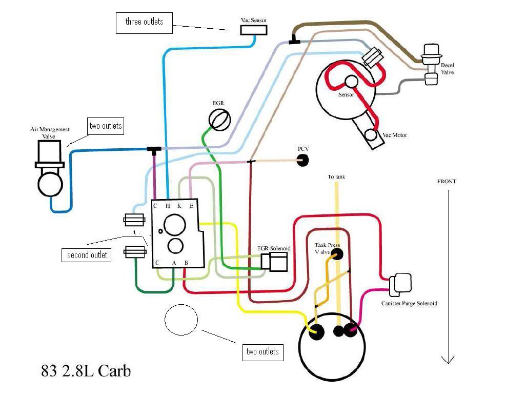
I need some help, I'm trying to pass smog and I was using one of the diagrams that was posted here, I just bought this 83 firebird, and I was trying to fix the vac hoses but it look like I had extra hoses and hoses un unplugged so I dont know what is suppose to go where, I never worked on a car before so I'm a lil lost, I follow the diagram but I see that I have extra hoses, n there are like outlets where I can plug those hoses, but I dont know where to connect what, since they dont appear on the vac diagram for my 83 2.8L 2BL firebird, is there a diagram that shows all the parts under the hood? Please Help Me
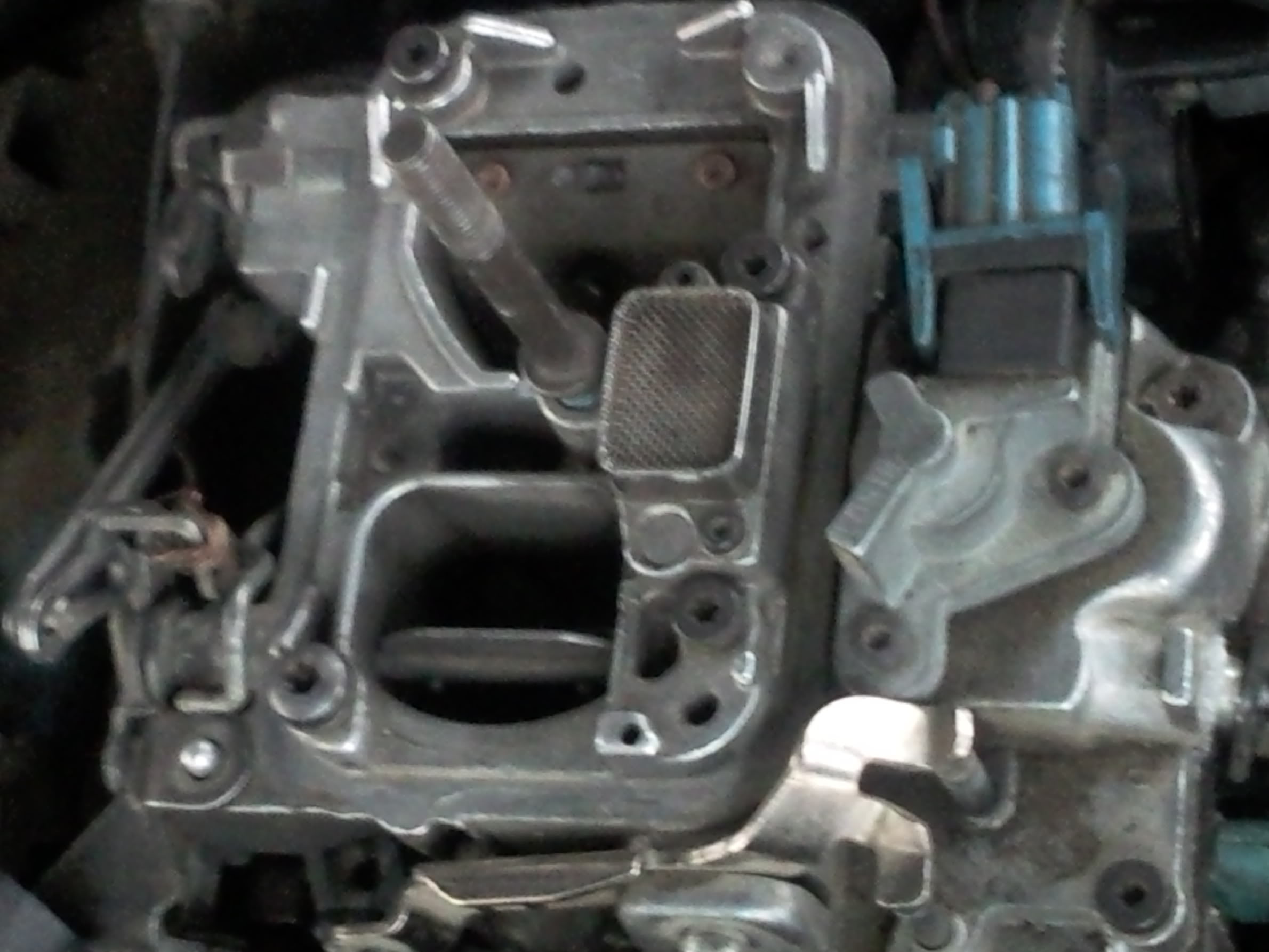
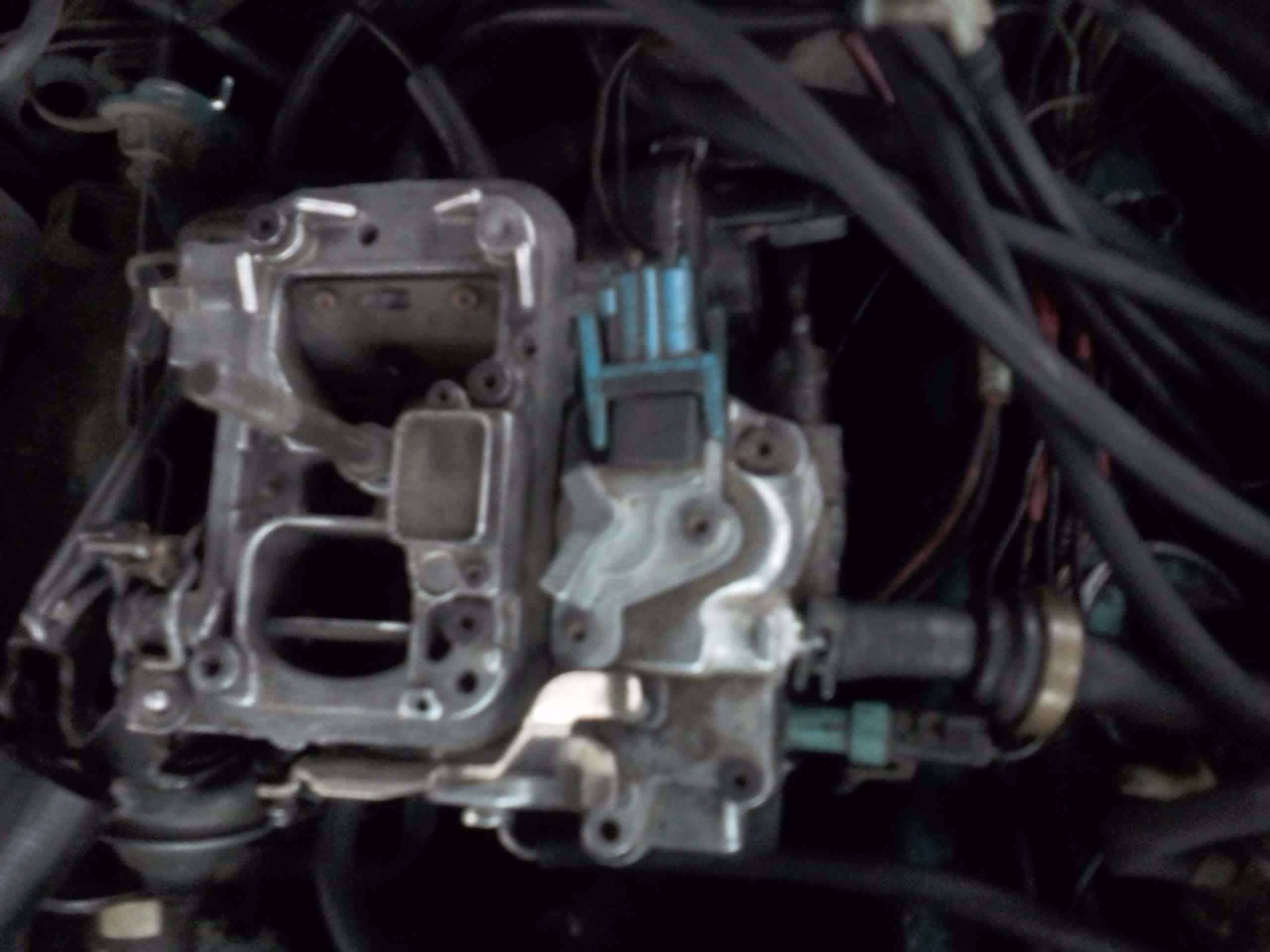
This is my carburetor
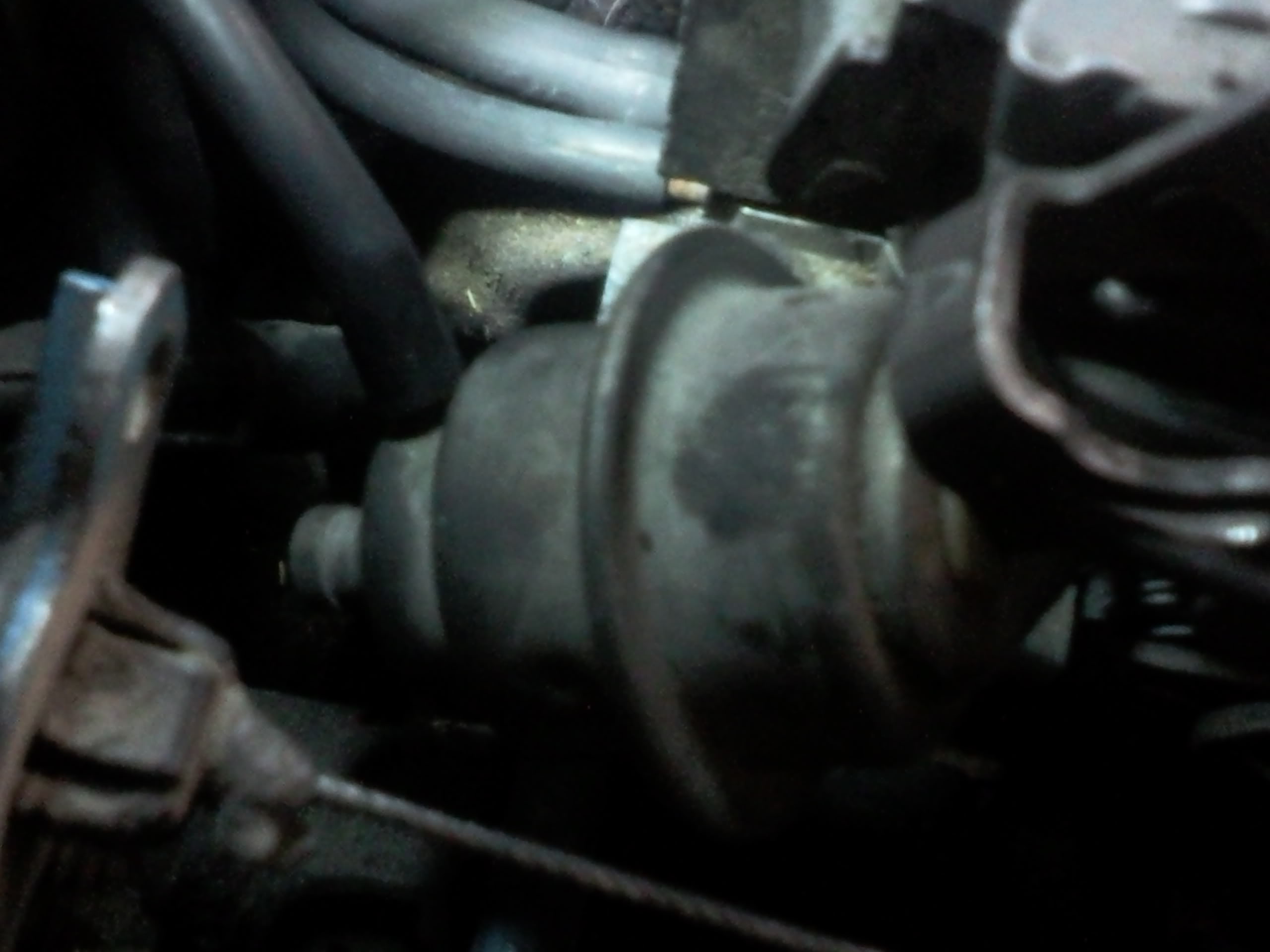
What is this? this are something on the left side of the carburetor they both have two outlets to connect some vac hoses but I dont know how to connect them, because on the diagram shows that they have only one outlet
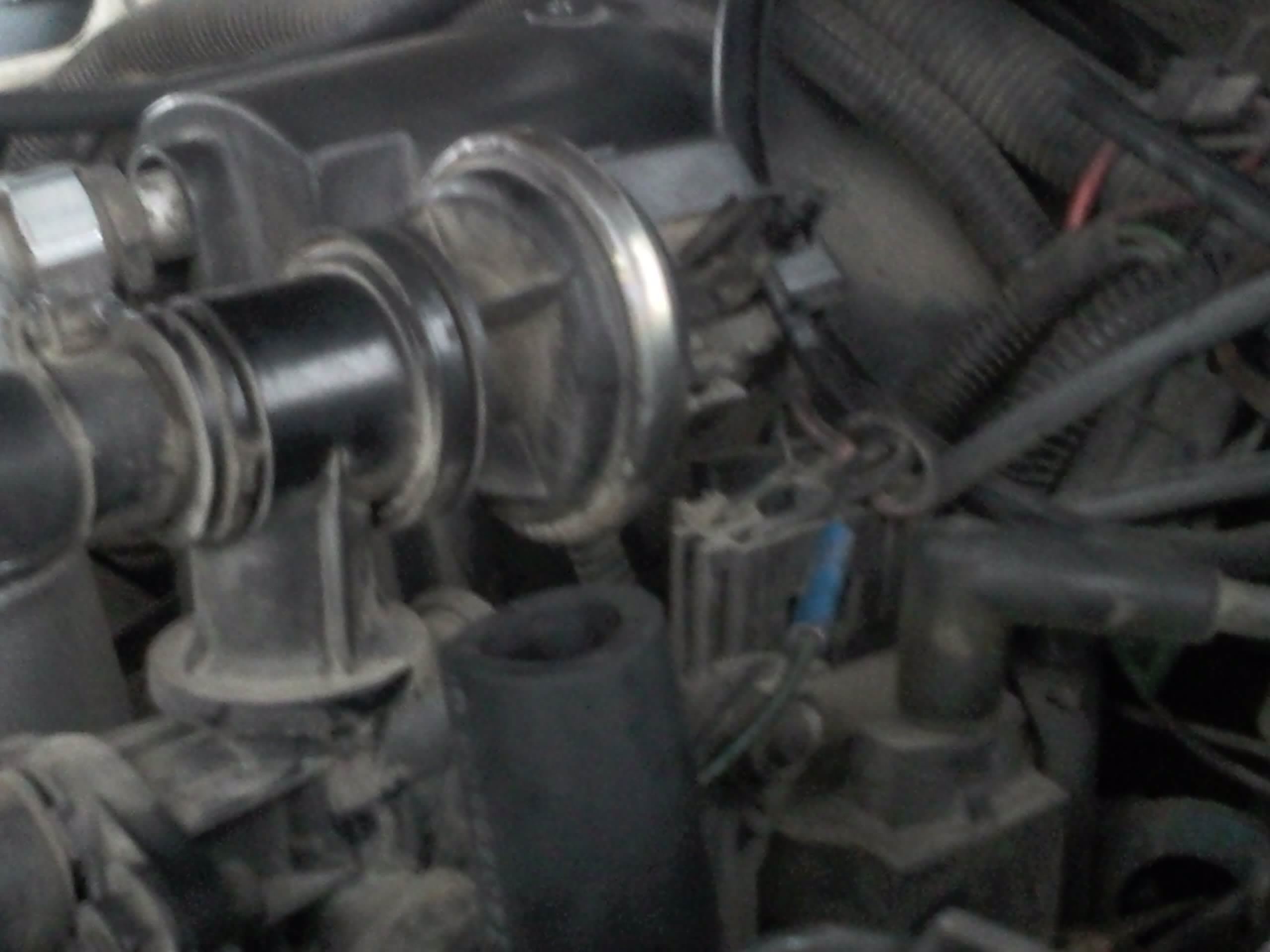
This is the air management valve, but it was 2 outlets on the top and a hose that is coming from the bottom and I dont know where they go
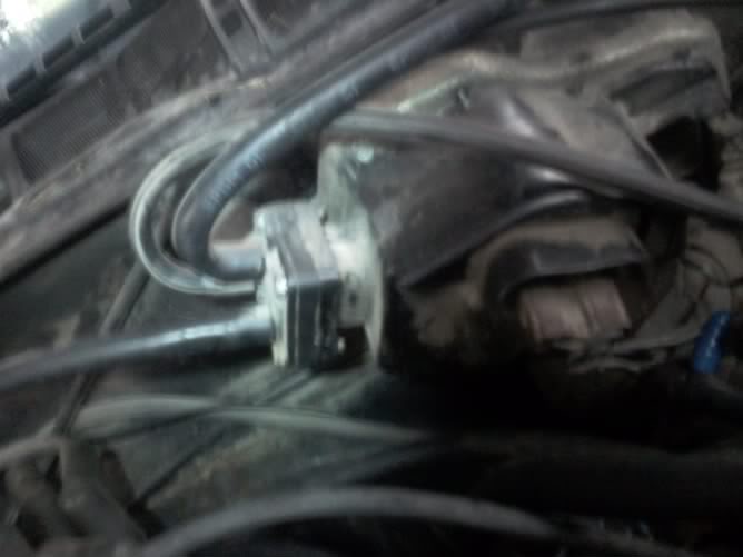
this is the vac sensor but as you can see it has 3 outlets which I dont know which one I'm suppose to use to connect it to the carburetor
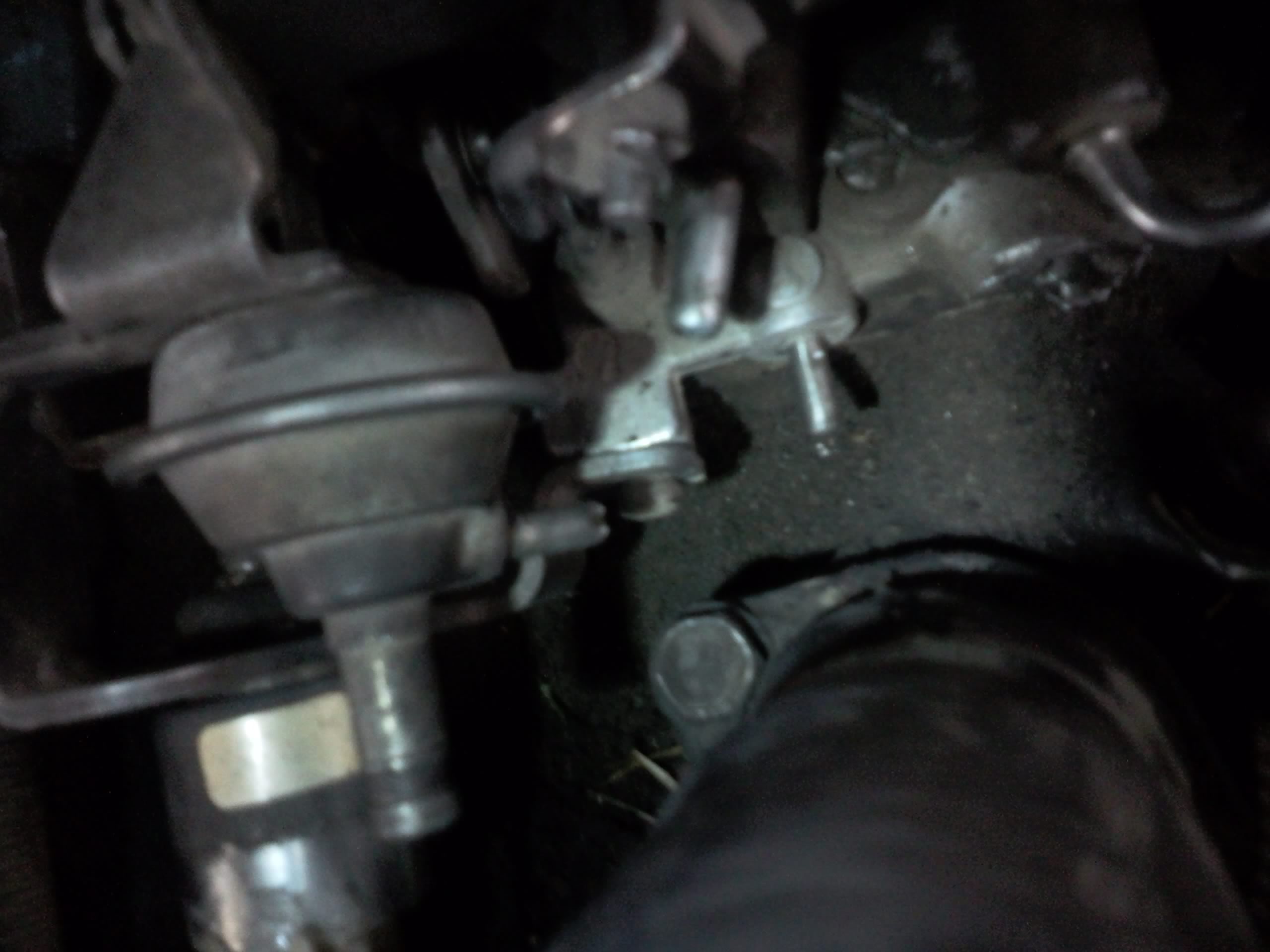
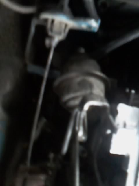
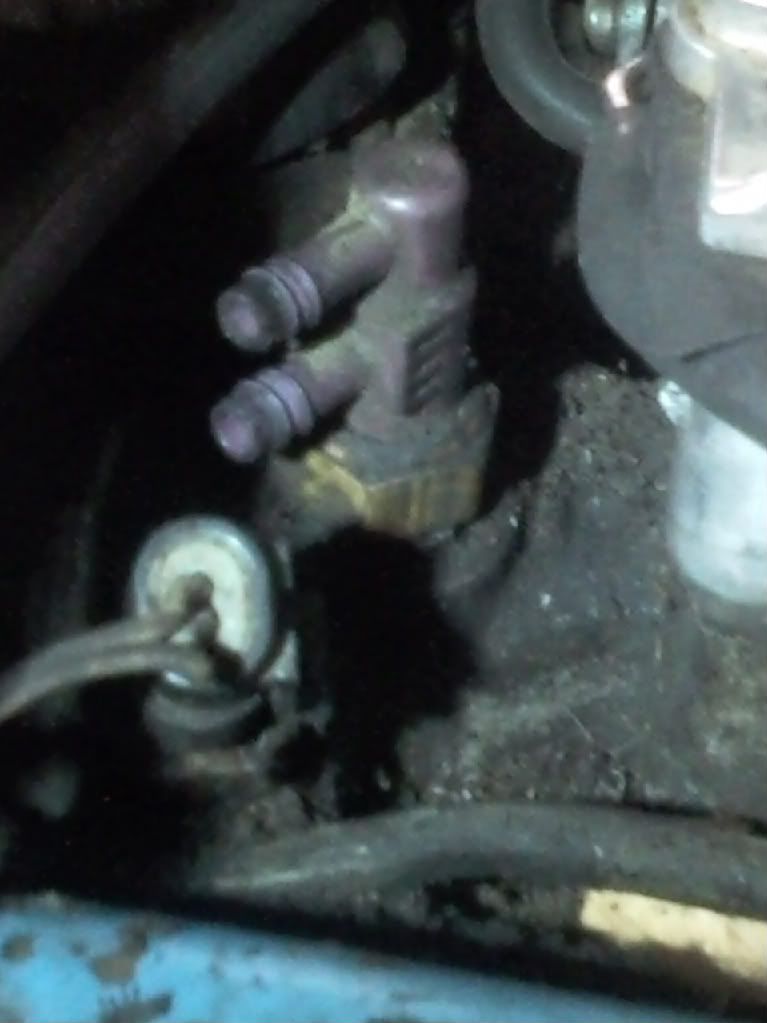
this part I dnt know what it is, it is located between the carburetor and the air injection pump,
This is my carburetor
What is this? this are something on the left side of the carburetor they both have two outlets to connect some vac hoses but I dont know how to connect them, because on the diagram shows that they have only one outlet
This is the air management valve, but it was 2 outlets on the top and a hose that is coming from the bottom and I dont know where they go
this is the vac sensor but as you can see it has 3 outlets which I dont know which one I'm suppose to use to connect it to the carburetor
this part I dnt know what it is, it is located between the carburetor and the air injection pump,
Supreme Member
iTrader: (8)
Joined: Aug 2003
Posts: 7,240
Likes: 6
From: LeRoy, NY
Car: 2003 Hyundai Tiburon GT
Engine: 2.7L V6
Transmission: 6-speed
Axle/Gears: 4.41
Re: Vacuum Diagram N Engine Components Locations
Don't know all of them. Looks like one of them could be a cruise control modulator that's missing both hoses (the one with 2 hose connections). That thing you call the vac sensor isn't the vac sensor... Don't know what it is, but the vac sensor is another name for the MAP/BARO sensor, which is used on most FWD V6 cars and has only one vac connection. And the last thing is what they call a temperature controlled vacuum delay valve, which opens at a certain coolant temp to allow vacuum to flow somewhere. May be known as an EGR or spark delay valve, to prevent the engine from stalling at cold temps by not allowing the EGR to open until the coolant reaches a certain temp.


Thread
Thread Starter
Forum
Replies
Last Post
NinjaNife
Tech / General Engine
27
Aug 23, 2015 11:49 AM