
Enough Closed Loop Info to be Dangerous

Thread Starter
Supreme Member
iTrader: (2)
Joined: May 2007
Posts: 2,574
Likes: 0
From: right behind you
Car: '85 maro
Engine: In the works...
Transmission: TH700 R4
Axle/Gears: 3.73 posi
Enough Closed Loop Info to be Dangerous
Having recently had to read through my entire calibration sevral times and testing out many irrelevant changes to my bin tracing down a problem that turned out to be quite simple (as always)- I thought it would be appropriate to set up a thread specific to modifying how closed loop is set up and how the o2 sensor you're using (wb or nb) plays into this. Info on the subject seems to be sparse and hasn't been explored all that much. As it's becoming more popular to use an LC1's simulated nb signal inplace of a nb sensor I think it may become neccecary for this information to become widespread. If you have something to contribute (personal experience, links, stories, whatever) please add. A couple good documents I reccomend having on hand are 'ECM Proportional Control' by Robert Rauscher and any good commented hack of $6E.
In my own experience with $3A, $1F, $32B and $6E I've learned that the closed loop control GM came up with sucks. It would be nice to completely wipe it out and start fresh with something more straight foreward based around a wb signal, but learning source code and programming isn't top on my to-do list. So for time being tweaking what GM gave us is the way to go. It's touchey and requires pretty specific calibration to get it to function properly, and does some wierd stuff when it's not happy. I haven't really delved into all the related tables & constants because there's alot there, but I can tell you that there's a whole nook of tuning that hasn't been taken advantage of. Most of what I'll be discussing is focused on $6E.
One of the first things you'll want to do is adjust the ecm's target o2 voltage to change the AFR it runs at. The tables to do this are the 'upper & lower 0 error for slow o2 tables (starting at LC0459 and LC0462)' and the 'closed loop rich/lean threshold (starting at LC046B)'. The target voltage 'window' formed by the 'upper & lower 0 error for slow o2' boundaries and the 'closed loop rich/lean threshold' must fall in a pretty narrow range within the o2's bandwidth, or more specifically the bandwidth that the ecm uses and expects to see. Move it too close to the 'edge' of the bandwidth and it will either cycle too frequently beyond what the ecm uses causing the ecm to set an error code, or the ecm won't see enough cross counts and upset the loop. The upper/lower boundaries must also be equally spaced from the median target voltage, or the INT will either be limited to enriching (upper boundary) or enleaning (lower boundary) depending on which boundary is off. This can make for some very frustrating diagnosing, particularly if it's only limited at a certain range because the voltage tables are often nonlinear, as gm programmed them.
Which leads me to the question of why GM decided to program them as they did. GM rarely uses the fabled .450v = stoich number, although it seems to be a valid number to the ecm in some form. Center of the bandwidth, maybe? Often times it's set to .5v in areas of the table that would correspond to typical cruising range. I see no need for the table to curve at all- perhaps it's to deal with varying conditions the sensor sees causing deviation from true stoich, maybe it's to improve performance or patch 'dips' in the power curve, or to improve emissions in certain areas... I don't know. If you're using the stock sensor you should probably keep the stock curve and only tweak it a little in areas to suit your needs. If you're using a programmable output from a wb I suggest you program them flat as can be- the sensor/controller should compensate for the conditions it's operating in.
There's some gains to be made from being able to vary the afr at certain points using a programmable nb signal, but really the ecm's bandwith is too narrow and the adjustments too coarse to give it wide adjustability and make it consistent. However since I've messed with it some I'll explain what's worked somewhat decent. First you need to get some idea of what the bandwidth your ecm is using and set your output to it. Typically it's about .05v to .85v, but I've set it as high as 1.1v- although I doubt it was useable. You don't want to set the low side too close to 0 volts either, the ecm will see the o2 sensor as unready and go open loop. Again, if it spends too long at a voltage it sees as unreasonable it will set a code. Then decide how far from stoich you need to go and how much you're willing to sacrifice resolution. IMO, any wider than 15.2:1 to 14.2:1 is too coarse to use without further changes in the bin, and beyond 16:1 to 13.4:1 is just impractical. The more you widen the range the smaller the prop gains (table starting at LC0486), o2 window and min error to enable INT (at LC0455) will need to be. Since I don't have catcons I set the prop gains low as possible. Keep in mind that you won't be able to use the entire AFR range you program, as explained above. Something else to consider is that the ecm uses the stored BLM offset during power enrichment as well. You could end up with a much richer wot AFR than you anticipated with modified o2 tables.
You can also improve the accuracy of what the ecm sees with a programmable signal. Since most widebands are much more responsive than stock sensors (enough to distingush individual gas pockets) this provides a much more dynamic view of what's exiting the engine. The values in the 'INT delay vs error table (staring at LC04BB)' must be adjusted some to take advantage of the improved response time, which is the intended use of the table. By increasing the filtering of the signal in the 'slow 0 error filter coefficient vs airflow table (staring at LC0474)' you get a more average reading and a more accurate view of what's going on inside the engine.
Now onto making closed loop work for you. When the signal's within the target voltage 'window' the ecm uses certain tables designed to keep the AFR around stoich. Here's where all the magic happens- it also happens to be a real PITA to get working just right. You want to spend as much time here as possible to maximize mileage and fueling consistency, unless it's running in highway mode which is another subject. The catch is that it was purposely designed to cycle rich/lean across the median target voltage to keep the catcons happy, and to keep the afr where it needs to be by playing marco-polo with the median voltage. We want to slow this cycle down for our purposes. Widening the o2 error window will cause the ecm to spend more time in the PID loop, and coupled with a reduced prop gain it will make smaller fueling changes less often while at steady cruise. If you reduce the prop gains enough the engine will operate almoast entirely within this window. Now you might think that the ecm would be happy sitting within this window, but it's not. If it doesn't see a cross count (crossing of the median voltage) within a certain amount of time it will force the INT to make a fueling change, upsetting the whole balance. And here's the whole game, leaving just enough prop gain to make it cycle just ahead of the time limit without making it cycle so much that it upsets the balance and sends it out of the window into 'AFR error correction'. When it's running outside this window another set of values take control. These are designed to make large afr swings to quickly locate stoich and gradually 'swing' it back into the window. I don't have much experience with those tables so I'm going to leave it out for now.
Something most people rarely consider changing that could net some decent mileage gains are the BLM cell boundaries (defined by the values at LC04C7 to LC04C9 and LC04CA to LC4CC). GM did a pretty good job setting these up in a manner that focused on the motor's normal operating range without making cell changes noticeable, however the closer you get these tables to the range you typically use the better your mileage should be. Where you set these points needs to be carefully considered to minimize large AFR jumps between cells. If placed in transitional areas the cell change will be abrupt and noticeable more often than not, the solution is positioning the BLM cell points just ahead of them. Placing them after will cause a lag during acceleration. There's also a bit to choose between using an air flow or load based BLM cell boundary (at LC0017 bit 0) which is particularly useful if your focus is on responsiveness instead of mileage.
Enabling closed loop sooner is also potentially useful. The 'rich/lean offset vs coolant temp table (starting at LC04AD)' can be used to change the AFR based on coolant temp allowing you to enable closed loop sooner while still reaching operating temp quickly. You'll need to change the enable parameters as well (obviously). If using an unheated sensor keep the original closed loop enable timers (at LC0448 to LC044A) and temp thresholds (at LC0446 and LC0447) and lower the closed loop enable constant (at LC0445). With a heated sensor you can modify the enable timers to however long it takes the sensor to warm up plus however long it takes for the startup enrichment to fully expire. Time must be allowed for engine components and the sensor to come up to temperature before closed loop is enabled regardless. The min BLM cell and BLM update temps (at LC04DF and LC04CF) should only be enabled at operating temp to stabilize long term fueling. If BLM cell updates are enabled too early false conditional compensation could result. In other words there could be a small vacuum leak or other problem that doesn't get adressed because of this. Because the coolant offset table only subtracts you'll need to offset the target o2 voltage tables to use this method.
A few more thoughts. If you have a modified exhaust system you'll need to adjust the 'INT delay vs airflow table (starting at LC0474)'. This table is used to compensate for transport delay- the delay from when a fueling change is made to when it shows up in the exhaust. A reliable method to do this is by measuring how long it takes for a blip of the throttle to show up on the wb with the stock exhaust, then measure with the new exhaust and find the % difference between the two and adjust the table entries by that amount. Idle quality can be improved by removing the additional prop gain added at idle (at LC0452), and reducing the additional INT delay at idle (at LC0451). You want to keep a little additional idle INT delay though so it doesn't get tweaky.
So there you have it. This should give you enough information to get started manipulating the way closed loop operates to your needs. Go slow and study what the chages you made do, especially with a modified motor. Things can get goofy quick when messing with the PID loop, but often times it's neccecary to keep the motor in the happy range.
Last edited by bl85c; May 16, 2009 at 04:52 PM.
Senior Member
Joined: Sep 2007
Posts: 1,091
Likes: 1
From: West Central Ohio
Car: 86 vette
Engine: 383
Transmission: 700R4
Axle/Gears: 3.07
Re: Enough Closed Loop Info to be Dangerous
Thanks for the well thought out post, there has to have been some long hours put in to come up with those paragraphs.
I have spend some time walking that CL path and everything that I have "discovered" (not near enough) follows your thinking. Thank you for sharing your thoughts on this "Deep" subject.
I have spend some time walking that CL path and everything that I have "discovered" (not near enough) follows your thinking. Thank you for sharing your thoughts on this "Deep" subject.
Thread Starter
Supreme Member
iTrader: (2)
Joined: May 2007
Posts: 2,574
Likes: 0
From: right behind you
Car: '85 maro
Engine: In the works...
Transmission: TH700 R4
Axle/Gears: 3.73 posi
Re: Enough Closed Loop Info to be Dangerous
I stayed up till 2am making sure it was clear as I wanted, LOL. What I want to do now is figure out exactly how the 'error correction' works so it doesn't take so long to settle back down on stoich. It can take as long as 30 seconds for it to fully swing it's way back to stoich.


Senior Member
Joined: Sep 2007
Posts: 1,091
Likes: 1
From: West Central Ohio
Car: 86 vette
Engine: 383
Transmission: 700R4
Axle/Gears: 3.07
Re: Enough Closed Loop Info to be Dangerous
I stayed up till 2am making sure it was clear as I wanted, LOL. What I want to do now is figure out exactly how the 'error correction' works so it doesn't take so long to settle back down on stoich. It can take as long as 30 seconds for it to fully swing it's way back to stoich.
My experience with error loops is with heat digital PID controllers. The ovens were overpowered and had thermal lag, big heaters and lots of steel and fire brick.
The challenge was at initial start up with a cold oven and loading (The door was one whole end of the oven, open then shut). The rule was +- 10* per 1000*. The oven was to run up to temp not overshoot and intermediately stabilize at set temperature, and recover after the door was opened and shut from loading product.
The two ways you could be "off" were to overshoot and oscillate around the set point (too much gain) or undershoot and oscillate around the set point (not enough gain). This is like the 30 sec time above.
How you ask, can the temp float or motor boat about the set point with both too much gain and not enough gain?
Here is how, with too much gain and/or too little delay the temp correction is knocked past the desired set point and then over corrects trying to get back but again over corrects. Think about a very quick steering car, small inputs make big changes. Everybody has seen this on a road track if you hit the curve too fast and over correct you will weave a few times and hit the ditch. Too little delay also causes the temp to chase the noise.
The other extreme is too little gain or too much delay, not enough input and nothing happens, then when it does react, it over reacts. Think of a car with slop in the steering, you turn the wheel nothing happens so you turn some more and then it goes but too much. If you are going slow but are slow to react you can follow almost the same path as the high gain, it will just take you farther down the track to wreck. Because of low gain or delay the reactions are behind the motion of the car or set point as to temp. Watch a little kid drive, some over crank the wheel and some are just too late.
The difference is when you steer a car you can either point where you want to go or if there is play to slowly turn the wheel right and left (weave the steering wheel) to keep the vehicle centered. Weave a tight high gain system and get what you input or try to just point a loose steering and it will wander too.
The end result is the same with the temp or path of the car, it weaves around the straight line you want. The trick is to match the natural frequency of the feedback loop so that the error correction is of the right size and timing to correct the natural tendency of the system to oscillate.
When I had the oven "correct" the set temp was steady with no change in the reading (+- .5*). Then when the door was opened and shut, temps would dip and return to the normal set temp. The rise to set temp was quick with no overshoot and immediately held to the steady +-.5* temp.
Some times it took days to get it right.
What does this have to do with an ECM Closed loop, everything. If you are too high on the gain and miss the sweet spot you can chase your tail alot, by making too big of a change. You need to "know" if you are too fast or too slow on the error correction. As you change the location of the O2 down the pipe you change the feedback time, so the gain or error correction has to be corrected. You also need to know if you are adjusting the fast O2 loop or the slow AFR loop.
The switch nature of the O2 sensor demands that the feedback oscillates (cross counts), to prove the operation of the O2 (the fast loop).
And also remember that some float is "designed into the system" to ensure that the cat is happy (the AFR slow loop).
How is this for more confusion.
Thread Starter
Supreme Member
iTrader: (2)
Joined: May 2007
Posts: 2,574
Likes: 0
From: right behind you
Car: '85 maro
Engine: In the works...
Transmission: TH700 R4
Axle/Gears: 3.73 posi
Re: Enough Closed Loop Info to be Dangerous
LOL. Maybe I can clarify it a little. The way I imagine it is a guy trying to find a lightswitch in a dark hall. But the lightswitch is constantly moving and making a quiet buzz. He has no idea how far he is from the switch or how fast it's moving, only if its ahead of him (lean) or behind (rich). Whenever he's next to it the room lights up and he can follow the lightswitch pretty easy, but it jumps around alot and it's hard to keep up. The longer he's in the dark the faster he'll run in the direction of the switch, and sometimes he jumps at it. And to make it even more frustrating there's always stuff in the way making him stop and wait. Only thing he has going for him is the fact that he has a good memory and can jump to places the lightswitch typically was in the past.
Member
Joined: May 2009
Posts: 153
Likes: 0
Re: Enough Closed Loop Info to be Dangerous
LOL. Maybe I can clarify it a little. The way I imagine it is a guy trying to find a lightswitch in a dark hall. But the lightswitch is constantly moving and making a quiet buzz. He has no idea how far he is from the switch or how fast it's moving, only if its ahead of him (lean) or behind (rich). Whenever he's next to it the room lights up and he can follow the lightswitch pretty easy, but it jumps around alot and it's hard to keep up. The longer he's in the dark the faster he'll run in the direction of the switch, and sometimes he jumps at it. And to make it even more frustrating there's always stuff in the way making him stop and wait. Only thing he has going for him is the fact that he has a good memory and can jump to places the lightswitch typically was in the past.

J/K. Not a bad analogy actually.
Trending Topics
Thread Starter
Supreme Member
iTrader: (2)
Joined: May 2007
Posts: 2,574
Likes: 0
From: right behind you
Car: '85 maro
Engine: In the works...
Transmission: TH700 R4
Axle/Gears: 3.73 posi
Re: Enough Closed Loop Info to be Dangerous
A few more thoughts on setting up BLM cells. You want the low points set just a bit above idle, including idle on deceleration from speed so you have two separate cells for idle in park and idle moving. These will be cells 0 and 1. Having 2 idle cells helps cut back on excess fuel useage due to fuel being pulled from the port walls during deceleration and subsequent leanness from that fuel being replaced, without DFCO or decel enlean being active. DFCO and decel enlean will help tremendously on decel, but they have their limits. Decel enlean was actually intended as a precursor to wall wetting compensation, however it's far too crude to be used as such.
You want the high points set a bit above the highest rpm/airflow you'll typically see during non-power enrichment events (like accelerating uphill) so you don't get into cell 15 (power enrichment cell) in closed loop. If you're doing any kind of wot tuning you don't want the ecm making adjustments in this cell and screwing up your careful tuning.
Now the difficult part is the mid points. I still haven't found a strategy that works well without making cell changes somewhat noticeable, but I've come up with 2 basic ideas. First is to set it close to your converter's stall speed since this is the point your engine will 'run up against' when going from cruise to accelerating, taking advantage of the tiny delay as the motor stalls against the converter to make the cell change and provide a bit of a boost with the afr change since more fuel is typically added at higher load regions. It will be noticeable, but not neccecarily bad ether and rather helpful because you won't need to jab the pedal as much to get going. This won't work with stick cars (obviously) or cars with loose converters that never really hit the stall point in normal driving. The other strategy is setting it near the range you typically cruse at, not at highway speeds. You don't want it set so low that it's constantly switching between cells during normal driving, but not so high that it lags when transitioning to accelerating. This can be really hard to get right because rpm and airflow are constantly changing in proportion to throttle and speed, and finding a condition that is rarely encountered to set these points at so cell changes are seamless is almoast impossible.
Separating high and low speed conditions via the mid points creates dedicated cells for both city and highway driving, and when set correctly another cell for acceleration. With careful attention to the way you drive and the conditons your motor sees you could potentially create dedicated cells for any condition your motor operates in. I've found that the way you have these cells set have a large impact on driveability and require lots of experimentation to find what works well, but are rewarding to work with in both mileage and driveability. Be sure to allow time for the ecm to readjust after changing things before determining what the actual effects are.
Last edited by bl85c; Jun 10, 2009 at 05:31 PM.
Senior Member
Joined: Sep 2007
Posts: 1,091
Likes: 1
From: West Central Ohio
Car: 86 vette
Engine: 383
Transmission: 700R4
Axle/Gears: 3.07
Re: Enough Closed Loop Info to be Dangerous
One of the first things you'll want to do is adjust the ecm's target o2 voltage to change the AFR it runs at. The tables to do this are the 'upper & lower 0 error for slow o2 tables (starting at LC0459 and LC0462)' and the 'closed loop rich/lean threshold (starting at LC046B)'. The target voltage 'window' formed by the 'upper & lower 0 error for slow o2' boundaries and the 'closed loop rich/lean threshold' must fall in a pretty narrow range within the o2's bandwidth, or more specifically the bandwidth that the ecm uses and expects to see. Move it too close to the 'edge' of the bandwidth and it will either cycle too frequently beyond what the ecm uses causing the ecm to set an error code, or the ecm won't see enough cross counts and upset the loop. The upper/lower boundaries must also be equally spaced from the median target voltage, or the INT will either be limited to enriching (upper boundary) or enleaning (lower boundary) depending on which boundary is off. This can make for some very frustrating diagnosing, particularly if it's only limited at a certain range because the voltage tables are often nonlinear, as gm programmed them.
While doing some open loop idle tuning, I was trying to get the open loop to match the closed. So I was adjusting the "Open Loop AFR % Chg vs Coolant Temp". This table allows you to match the AFR of the open loop to the closed.
Now here is the observation, at an open loop AFR (commanded) of 14.89, the NB ran in the high 850 to 900 mv. This is the NB at a very rich reading.
So for the next test I lower the "Open Loop AFR % Chg vs Coolant Temp" by one dec number (this is the smallest change that can be made). The commanded open loop AFR dropped to 14.93 and the NB output dropped to around 50 mv which is very lean.
My normal closed loop AFR is 15.00 and the NB O2 swings the full range from 850 to 50 mv.
This shows just how narrow the "Band width" of a NB O2 is. I was surprised that such a small change in the open loop AFR made such a big difference in the NB output.
So when my NB O2 swings in normal closed loop, it is only changing the AFR by .04, this is a very small amount.
I can give the details of my test to any one who would like to try it.
Senior Member
Joined: Feb 2005
Posts: 617
Likes: 0
From: Rochester,NY
Car: 1993 Caprice wagon "Shammoo"
Engine: tpi'd 406, with P4 ebl EBL 730 ECM
Transmission: custom "4L65" swap.
Axle/Gears: 3.42:1 with posi
Re: Enough Closed Loop Info to be Dangerous
Great posts... I followed your analogies. Someday I hope this is a problem for me. For now, I'd like to get mine past the "crank, no start" stage.
Thread Starter
Supreme Member
iTrader: (2)
Joined: May 2007
Posts: 2,574
Likes: 0
From: right behind you
Car: '85 maro
Engine: In the works...
Transmission: TH700 R4
Axle/Gears: 3.73 posi
Re: Enough Closed Loop Info to be Dangerous
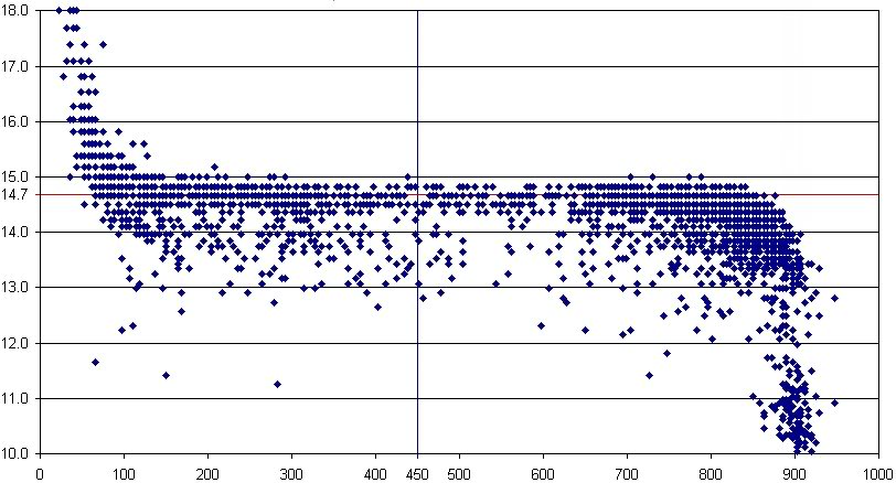
Just to give you an idea as to how little of a change in AFR effects the NB output.
While doing some open loop idle tuning, I was trying to get the open loop to match the closed. So I was adjusting the "Open Loop AFR % Chg vs Coolant Temp". This table allows you to match the AFR of the open loop to the closed.
Now here is the observation, at an open loop AFR (commanded) of 14.89, the NB ran in the high 850 to 900 mv. This is the NB at a very rich reading.
So for the next test I lower the "Open Loop AFR % Chg vs Coolant Temp" by one dec number (this is the smallest change that can be made). The commanded open loop AFR dropped to 14.93 and the NB output dropped to around 50 mv which is very lean.
My normal closed loop AFR is 15.00 and the NB O2 swings the full range from 850 to 50 mv.
This shows just how narrow the "Band width" of a NB O2 is. I was surprised that such a small change in the open loop AFR made such a big difference in the NB output.
So when my NB O2 swings in normal closed loop, it is only changing the AFR by .04, this is a very small amount.
I can give the details of my test to any one who would like to try it.
Last edited by bl85c; Jun 14, 2009 at 05:17 PM.
Senior Member
Joined: Sep 2007
Posts: 1,091
Likes: 1
From: West Central Ohio
Car: 86 vette
Engine: 383
Transmission: 700R4
Axle/Gears: 3.07
Re: Enough Closed Loop Info to be Dangerous
There are two ways to look at the NBO2, one is plot the O2 mv while in closed loop. That is the chart above. And the other is to feed a fixed AFR to the engine and plot the O2 mv at a steady state (idle), this is what I did. My results showed that very minor changes in the open loop AFR cause very large changes in the O2 mv. The biggest difference is that the ECM in open loop, is not "a dog chasing it's tail" as it is in closed. Most who tune open loop never look at what the O2 mv readings because they quickly become very useless.
I have seen this behavior in a closed loop servo feedback circuit on a CNC electric motor drive. The feedback is a dc tach or ac resolver. You can roll the output shaft attached to the feedback device and watch the motor turn, (being mechanically disconnected from the drive shaft), as you get close to the position set point, the motor will slow down and reverse direction, then quickly speed up in the opposite direction. If you have a steady hand you can even stop the motor and hold it's position motionless. At that spot is where the CNC wants the drive shaft to be.
Some people think that if you are in open loop that the O2 readings are "turned off" but in reality they are still read to the data stream, but are just not used to modify the AFR.
Member
Joined: Sep 2003
Posts: 232
Likes: 0
Car: 2011 6.2 Silverado, 88/85 camaro
Re: Enough Closed Loop Info to be Dangerous
I'm bumping this thread back up, its great information. I love this type of stuff. I took a chem class, had a hard time, because it was all nutrition related... and it was a class with a county ballistics guy as my partner and we wanted to make gun powder... not seperate fruit juice to see how much sugar was in it. Anyway, this is the type of technical info that gets my juices going! That and the intracasies of female erogenous tactics.

Thread
Thread Starter
Forum
Replies
Last Post
83 Crossfire TA
Suspension and Chassis
6
Sep 18, 2015 12:01 PM
83 Crossfire TA
Suspension and Chassis
0
Sep 8, 2015 12:06 PM