
Limp Home Mode Clarification

Thread Starter
Member
Joined: Apr 2013
Posts: 145
Likes: 0
Limp Home Mode Clarification
When using a V6 memcal and cutting the 15k resistor the circuit then becomes V8 and Limp Home Mode works as any V8. I cut the pin and removed the 28 pin chip and it ran in mine with the SES light on as it should.
Hopefully this will put an end to misinformation being given here on this Forum.
Hopefully this will put an end to misinformation being given here on this Forum.


Joined: Dec 2004
Posts: 16,900
Likes: 1,014
From: Mile High Country !!!
Car: 1967 Camaro, 91 z28
Engine: Lb9
Transmission: M20
Axle/Gears: J65 pbr on stock posi 10bolt
Re: Limp Home Mode Clarification
When using a V6 memcal and cutting the 15k resistor the circuit then becomes V8 and Limp Home Mode works as any V8. I cut the pin and removed the 28 pin chip and it ran in mine with the SES light on as it should.
Hopefully this will put an end to misinformation being given here on this Forum.
Hopefully this will put an end to misinformation being given here on this Forum.
Thread Starter
Member
Joined: Apr 2013
Posts: 145
Likes: 0
Re: Limp Home Mode Clarification
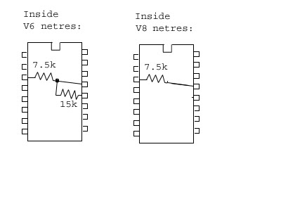
This post lead me to a test. The memcal shown on the right where the pin to the 15k resistor is cut runs in Limp Home Mode. The memcal on the left where the 15k resistor is grounded does not run in Limp Home Mode. Therefore, cutting the 15k resistor pin is the superior method if you still want to have Limp Home Mode.

Joined: Dec 2004
Posts: 16,900
Likes: 1,014
From: Mile High Country !!!
Car: 1967 Camaro, 91 z28
Engine: Lb9
Transmission: M20
Axle/Gears: J65 pbr on stock posi 10bolt
Re: Limp Home Mode Clarification
This post lead me to a test. The memcal shown on the right where the pin to the 15k resistor is cut runs in Limp Home Mode. The memcal on the left where the 15k resistor is grounded does not run in Limp Home Mode. Therefore, cutting the 15k resistor pin is the superior method if you still want to have Limp Home Mode.
Or is it you can have correct cyl select or lhm but not both ?
Trending Topics

Moderator
iTrader: (1)
Joined: Mar 2002
Posts: 18,432
Likes: 234
From: Chasing Electrons
Car: check
Engine: check
Transmission: check
Re: Limp Home Mode Clarification
Wrong pin. Need to ground the one that corresponds to pin 56 of the MEMCAL (next one over). Basically you shorted a +5 volt feed to the MEMCAL to ground. Which is likely why LHM doesn't work.
RBob.
RBob.
Thread Starter
Member
Joined: Apr 2013
Posts: 145
Likes: 0
Re: Limp Home Mode Clarification
I ground pin 56 and it ran in LHM with an SES light so I soldered in a chip and burned it and it ran without any codes. So either cutting pin 58 or grounding 56 will work.
Moderator
iTrader: (1)
Joined: Mar 2002
Posts: 18,432
Likes: 234
From: Chasing Electrons
Car: check
Engine: check
Transmission: check
Re: Limp Home Mode Clarification
So we are back to what we the forum have been saying all along. To use a 6-cylinder MEMCAL for an 8-cylinder engine, ground pin 56.
RBob.
Joined: Dec 2004
Posts: 16,900
Likes: 1,014
From: Mile High Country !!!
Car: 1967 Camaro, 91 z28
Engine: Lb9
Transmission: M20
Axle/Gears: J65 pbr on stock posi 10bolt
Re: Limp Home Mode Clarification
Additional information regarding knock sensor disabling.
https://www.thirdgen.org/forums/diy-...d-density.html
https://www.thirdgen.org/forums/diy-...d-density.html
Thread Starter
Member
Joined: Apr 2013
Posts: 145
Likes: 0
Re: Limp Home Mode Clarification
I will just have to disagree with your assesment because grounding can leave a cold solder joint so cutting 58 is more reliable.
https://pcmhacking.net/forums/viewto...t=214&start=20
https://pcmhacking.net/forums/viewto...t=214&start=20
Last edited by MrWillys; Jun 10, 2017 at 01:47 PM.
Joined: Dec 2004
Posts: 16,900
Likes: 1,014
From: Mile High Country !!!
Car: 1967 Camaro, 91 z28
Engine: Lb9
Transmission: M20
Axle/Gears: J65 pbr on stock posi 10bolt
Re: Limp Home Mode Clarification
I will just have to disagree with your assesment because grounding can leave a cold solder joint so cutting 58 is more reliable.
https://pcmhacking.net/forums/viewto...t=214&start=20
https://pcmhacking.net/forums/viewto...t=214&start=20
Thread Starter
Member
Joined: Apr 2013
Posts: 145
Likes: 0
Re: Limp Home Mode Clarification
Disagree and have tuned more than 1000 vehicles in 15 years. What detriment do you speak of? Are all the guys down under wrong too?
Moderator
iTrader: (1)
Joined: Mar 2002
Posts: 18,432
Likes: 234
From: Chasing Electrons
Car: check
Engine: check
Transmission: check
Re: Limp Home Mode Clarification
I will just have to disagree with your assesment because grounding can leave a cold solder joint so cutting 58 is more reliable.
https://pcmhacking.net/forums/viewto...t=214&start=20
https://pcmhacking.net/forums/viewto...t=214&start=20
And from your first post:
> Hopefully this will put an end to misinformation being given here on this Forum.
Apparently you are the one spreading misinformation. We the forum have been correct all along with grounding pin 56...
RBob.
Thread Starter
Member
Joined: Apr 2013
Posts: 145
Likes: 0
Re: Limp Home Mode Clarification
My point was to simply point out that LHM mode does function in V6 memcal conversions and will now stay true to my word to keep my post count low on this my way or the highway forum. this thread has made my point quite clear and the responses speak quite clearly. Have a good day!
Joined: Mar 2006
Posts: 4,370
Likes: 19
Car: 1973 Datsun 240Z/ 1985 S-15 Jimmy
Engine: Turbo LX9/To be decided
Transmission: 5-speed/T-5
Axle/Gears: R200 3.90/7.5" 3.73
Re: Limp Home Mode Clarification
It may work, but it won't be the same as using a true V8 RFD chip.
I could claim all sorts of LHM inaccuracies, because I've used turbo V6 MEMCALs with the "wrong MAP sensor" (2 BAR vs 3 BAR), it would allow the engine to start and run, but in no way would I claim that it is correct, or just as good as using the proper matching components.
I've used 4 cyl MEMCALs with V6s, and the engine would run, again, in no way would I say that this is a correct application of parts, simply because the engine started because it's not.
Even a broken clock is correct twice a day...

TGO Supporter
Joined: Aug 2001
Posts: 1,008
Likes: 0
From: NJ/PA
Car: Yes
Engine: Many
Transmission: Quite a few
Re: Limp Home Mode Clarification
I haven't replied on the boards in YEARs, but what is said above is correct. the memcal for 730 ecms contains three parts. prom, knock board, and resnet. each has their specific purposes. each memcal is unique and can be verified by measuring pin 48 of the memcal. the knock value and resnets are configured to match the engine it's designed to run with, including limp home values and knock frequencies. each one has a unique resistor value.
here is a snippet from one of the boards of long ago, maybe diy-efi.org or gm-ecm. can't remember. bottom line is grounding to set the pin to zero volts should set the memcal to believe it's 8 cylinder port injection.
I've just discovered how to select the number of cylinders in the P4 ECM
> hardware. The number of cylinders is selected by the voltage on pin 11
> on the 34984 (aka 79435) chip. This is U13 in a '727, '730, and '749.
> The pin 11 voltage comes from pin 56 of the MEMCAL. This in turn
> connects to pin 13 of the 16 pin resistor network in the MEMCAL.
>
> Here's how the voltages are interpreted:
> 0 to 1 volt : 8 cylinder port injection
> 1 to 2.5 volts : 6 cylinder port injection
> 2.5 to 4 volts : 4 cylinder port injection
> 4 to 5 volts : throttle body injection (any cylinder count)
>
> The '727 I tested this on defaulted to "4 cylinder port" when pin 11 was
> not driven (no MEMCAL).
>
> The CPU can read out the pin 11 mode selection. Code 41 will be flagged
> if it doesn't match the cylinder selection stored separately in the
> MEMCAL's EPROM.