
Transam Headlight motor circuit


Thread Starter
Senior Member

Joined: Jun 2016
Posts: 520
Likes: 28
From: Malta
Car: 1988 Trans AM GTA
Engine: 350 TPI
Transmission: 700R4
Axle/Gears: 9-Bolt 3.27
Transam Headlight motor circuit
I am currently tidying up some mess other owners did and am at a point of doing the headlight harness. Mine is the one with 3 relays (Isolating and 2x Actuators).
When everything was assembled I always noticed that one of the headlamp opens with a slight delay and at times none of them opened until you click multiple times the switch. Could well be the motors themselves but now that I have the loom apart it is obvious someone messed with it at a certain point so I wanted to tidy up the mess.
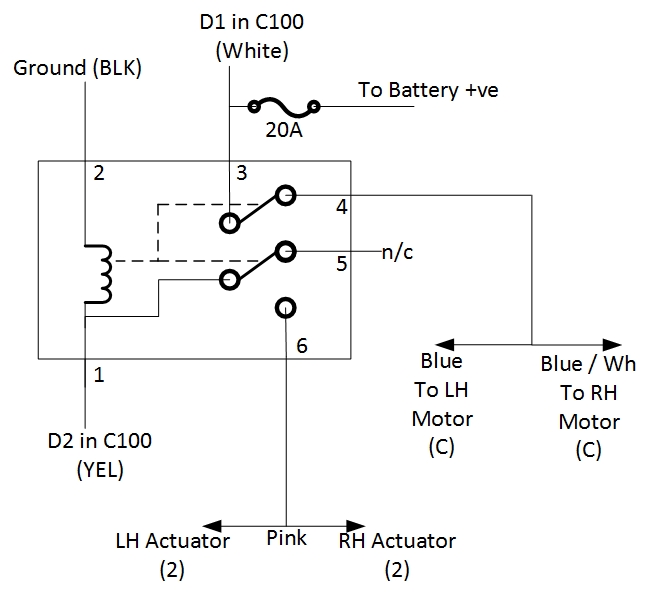
The actuator relays seem untouched however the isolating relay has very strange wiring swapped polarities and bridged outputs. As I do not have a visible number on the relay on which i can cross check the internals, I built a diagram of what I think is the internal structure. Logically it makes sense to work the same way to the original although very different. Can someone please let me know if this modification was ever done and also what are the disadvantages of having the Blue, White/Blue wires being supplied through the same relay pin?
When everything was assembled I always noticed that one of the headlamp opens with a slight delay and at times none of them opened until you click multiple times the switch. Could well be the motors themselves but now that I have the loom apart it is obvious someone messed with it at a certain point so I wanted to tidy up the mess.
The actuator relays seem untouched however the isolating relay has very strange wiring swapped polarities and bridged outputs. As I do not have a visible number on the relay on which i can cross check the internals, I built a diagram of what I think is the internal structure. Logically it makes sense to work the same way to the original although very different. Can someone please let me know if this modification was ever done and also what are the disadvantages of having the Blue, White/Blue wires being supplied through the same relay pin?
Thread Starter
Senior Member
Joined: Jun 2016
Posts: 520
Likes: 28
From: Malta
Car: 1988 Trans AM GTA
Engine: 350 TPI
Transmission: 700R4
Axle/Gears: 9-Bolt 3.27
Re: Transam Headlight motor circuit
In view of the lack of feedback from anyone here on the forum, I decided I need to investigate further. I opened my isolation relay and diagrammed it. Attached is the actual internal circuitry. 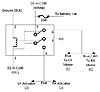
Looking at my diagram after a while i discovered that it is actually the curcuit of the actuator relay. So my next step was to investigate the other two which are the actuator relays. As expected, they were the same with the exception that for some unknown reason, the RH actuator relay has a 580Ohm resistor across the coil windings.
So my next question is:
Is it a common practice using an actuator relay instead of an isolating relay and fiddling the wires to end up as per my diagram?
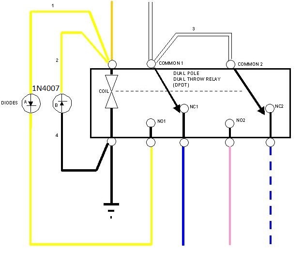
Did anyone ever tried the other attachment that I am putting here using a normal DPDT relay in place of the isolating relay?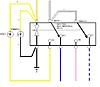
Looking at my diagram after a while i discovered that it is actually the curcuit of the actuator relay. So my next step was to investigate the other two which are the actuator relays. As expected, they were the same with the exception that for some unknown reason, the RH actuator relay has a 580Ohm resistor across the coil windings.
So my next question is:
Is it a common practice using an actuator relay instead of an isolating relay and fiddling the wires to end up as per my diagram?
Did anyone ever tried the other attachment that I am putting here using a normal DPDT relay in place of the isolating relay?


Re: Transam Headlight motor circuit
 Hi aseychell ,
 I'm sorry no one answered your question and sadly I have no input to offer you except this ;
I have read here that the isolation relay is a discontinued part , now made from "unobtainum" it would seem , and that there is a "backyard hack" wiring change that will allow the use of a different , commonly obtainable relay in it's place . I saw where one gent posted up a link to a Pontiac Fiero forum (this car used the same pop up headlights ous did) that showed the wiring diagram of the changes needed to use the available relay .
If a search of "isolation relay" here produces no results a search of the Fiero forums should turn up the schematic for the wiring change .
Thread Starter
Senior Member
Joined: Jun 2016
Posts: 520
Likes: 28
From: Malta
Car: 1988 Trans AM GTA
Engine: 350 TPI
Transmission: 700R4
Axle/Gears: 9-Bolt 3.27
Re: Transam Headlight motor circuit
The second diagram was actually found on a fiero forum. Will see how easy it is to find A DPDT relay and keep this post updated for others to use
Thread Starter
Senior Member
Joined: Jun 2016
Posts: 520
Likes: 28
From: Malta
Car: 1988 Trans AM GTA
Engine: 350 TPI
Transmission: 700R4
Axle/Gears: 9-Bolt 3.27
Re: Transam Headlight motor circuit
Last weekend I built the two relay circuit to 'emulate' my missing isolation relay. I have also properly wired the circuit and removed the 'external' 12v Source the PO did directly from the battery.
The hedlight switch was not supplying 12V on the White wire while in the off position and the issue was simply dirty contact and a weak contact metal.
You can see the final product on the relays and also the open switch.
The red circle shows where the Off 12V Signal contact was not being made. It should send 12V from the blue marked contact to the red circle which in turn supplies the White wire to the isolating relay.
Thread Starter
Senior Member
Joined: Jun 2016
Posts: 520
Likes: 28
From: Malta
Car: 1988 Trans AM GTA
Engine: 350 TPI
Transmission: 700R4
Axle/Gears: 9-Bolt 3.27
Re: Transam Headlight motor circuit
Forgot to add that now I have a problem with one of the headlight motors itself. Looks to me like a limiter switch is not working properly as as soon as I power the loom I can hear the of the motors trying to work. Then I push the Head switch, both lights go up however the same motor that I hear the first time while off I also hear it still trying to turn (while headlamps are up). When I put them in Off again, the same headlight does not go down and I have to go a slightly touch the manual **** for it to go down.
I know this 3 wire system uses a limiter switch and not a spike detection as in the 2-wire with the control box. Did anyone every fix these limiter switches or are they embedded in an unserviceable way?
I know this 3 wire system uses a limiter switch and not a spike detection as in the 2-wire with the control box. Did anyone every fix these limiter switches or are they embedded in an unserviceable way?
TGO Supporter
Joined: Sep 2000
Posts: 6,775
Likes: 27
From: So.west IN
Car: 87 Formula/ 00 Xtreme
Engine: TPI 305/ v6
Transmission: struggling t-5/ 4l60E
Axle/Gears: 3.08/ 3.23
Re: Transam Headlight motor circuit
This may/may not help you but, here it is, at least...
https://www.thirdgen.org/forums/elec...headlight.html
https://www.thirdgen.org/forums/elec...headlight.html
Trending Topics
Thread Starter
Senior Member
Joined: Jun 2016
Posts: 520
Likes: 28
From: Malta
Car: 1988 Trans AM GTA
Engine: 350 TPI
Transmission: 700R4
Axle/Gears: 9-Bolt 3.27
Re: Transam Headlight motor circuit
A lot of good stuff in that link thanks!! Will go through them and see what I come up with

Junior Member

Joined: Jul 2013
Posts: 75
Likes: 1
Car: 89 GTA, 84 T/A
Engine: L98 stock, Carbed 350
Transmission: 700r4
Axle/Gears: 3.27
Re: Transam Headlight motor circuit
To confirm, when the switch is off, the pin F, (white) should have continuity with pin a (orange).
I checked three different switches with my multi meter and get nothing.
I am having problems with my 89 headlight module which needs the white line.
I checked three different switches with my multi meter and get nothing.
I am having problems with my 89 headlight module which needs the white line.
Last edited by allos; May 18, 2017 at 02:44 PM. Reason: wrong pin
Thread Starter
Senior Member
Joined: Jun 2016
Posts: 520
Likes: 28
From: Malta
Car: 1988 Trans AM GTA
Engine: 350 TPI
Transmission: 700R4
Axle/Gears: 9-Bolt 3.27
Re: Transam Headlight motor circuit
When the switch is off it should supply 12V to the White wire. Not sure on what color is the 12V source however if you look at my opened switch picture above, the permanent 12v is found on the switch terminal with a blue oval in the picture.
Mine did not have a headlight module but a 3-relay setup so cannot really comment on your arrangement.
Mine did not have a headlight module but a 3-relay setup so cannot really comment on your arrangement.