
4th gen heater ducting done right

Thread Starter
Senior Member

Joined: Sep 2006
Posts: 573
Likes: 9
From: San Antonio, Tx
Car: 1988 Camaro IROC-Z
Engine: LB9 (305 TPI)
Transmission: 700R4
Axle/Gears: 2.73 Positraction
4th gen heater ducting done right
After going thru all the 4th gen dash swaps on this forum, I've noticed that almost everyone goes the shortcut route and tries to re-use their 3rd gen heater ducting with their 4th gen dash. This generally has the end result of a working defrost and leg vents, but no main vents. This is because the 4th gen ducting is different enough that the 3rd gen cannot be made to allow full function of the various climate settings. However, the 4th gen ducting will not fit in its factory form with the 3rd gen firewall.
Luckily, with a little modification to both the firewall and the 4th gen ducting, it can be made to work and full function of the climate settings can be had. This modification was done to my 83 Z/28 Camaro with a 94 dash install, and is currently working. Materials needed are;
1/4" head self tapping sheet metal screws
20-22 gauge sheet metal (16" by 18" sheet minimum)
all purpose exterior rated 3hr rain-ready silicone caulk
2 sheets foam sheet (available at hobby/craft stores)
1" thick foam (can be re-used from the 3rd gen ducting)
air cutoff wheel
dremel tool
sheet metal cutters
sharpie marker
caulk gun
super glue
First, use the dremel to remove the excess material around the edges of the heater core end of the 4th gen heater ducting. This lip is not needed on our modification. Refer to the pictures below for how much to remove. Then begin testing for fitment by attaching the 4th gen ducting to the 4th gen dash and hold it in place with tape, and test fit the whole assembly as close to it's final mounting position as possible. Then use a sharpie marker to mark along the top of the firewall where the edges of the heater ducting will mate to the firewall. These will be your reference marks for measuring the placement of your modifications. Nothing too scientific here, best guesstimates seemed to work for me. Take the dash assembly back out and remove the heater ducting from the dash. Now place it against the firewall as best as possible (stuff will still be in the way, don't worry), and line it up with the marks. Now you can see how much of the 3rd gen air recirculation valve location will have to be removed for the 4th gen heater ducting to fit. Mark with the sharpie a vertical line at least 1/2" - 3/4" from the edge of the 4th gen heater ducting on the recirc, and again horizontally above the 4th gen ducting. The vertical line should be as close to without touching the edge of the recirc vent as possible.
Now mark lines straight to the firewall along the recirc housing. Your goal is to make a square cutout in the side of the housing, removing the 45 degree section completely. This will notch the housing so that the 4th gen heater ducting will fit next to it perfectly, without affecting the function of the cowl vent drain or recirc vent. After marking, remove the recirc vent so as not to damage it in our next step. Now take your air cutoff wheel and carefully cut along the lines you marked, going slowly and making gradually deeper passes. Do not try to deeply cut in one pass, you risk either cutting too far or going thru the firewall into the engine bay. After making all your cuts, test fit the 4th gen heater ducting. It should look something like this now.
If your 4th gen heater ducting now fits in the notch you just created, you're halfway done. Now you need to mark the location of your heater core tubes, and modify the firewall heater box opening slightly for the new placement. Using my pics as a basis and your ducting's fitment, mark the approximate location the pipes need to pass thru the firewall, and the base of your ducting's opening. The lower part of the firewall opening should have to be lowered about 1 1/2" - 2", the right side about 1/2" down and 2" - 2 1/2" out, and the tubes should have a rectangular opening cut for them at the top of the opening about 1/2" in from the left, 1" tall, and about 2" - 3" long. Start small and test fit as you go so as not to make the openings too large. Be sure to check from the engine side of the firewall also, it makes perfect fitment much easier. DOUBLE CHECK YOUR MEASUREMENTS BEFORE YOU CUT. Use my pics as a GUIDE only. Once you have this done, you're ready to close up the notch in the air recirc vent housing. Take careful measurements and lay out the basic design 2-dimensionally on a piece of cardboard. You want to start with the large square vertical area first, the measure and lay out the upper horizontal area, and the firewall side large triangular area. The goal is to make a flat cutout that can then be folded into a three dimensional piece that will fit perfectly into the notch you cut in the air recirc vent housing. Be sure to leave a 1/2" - 3/4" tab at either end of the square areas, these will be the attachment points that fit over top of the air recirc vent housing and get attached with the self tapping sheet metal screws. Once your cardboard template fits properly, transfer the design to your piece of sheet metal either by tracing it or measuring it and re-drawing it. Be sure to mark your fold lines, this will help when you cut it out and bend the metal later. Use sheet metal cutters and go carefully, also making sure to cut at least an 1/4" on all your folds to help them stay lined up. Once the shape is cut out, use a sturdy straight edge and bend your folds to 90 degrees. Your finished sheet metal piece should match your cardboard test piece and fit perfectly into the notch in the air recirc vent housing. Don't worry if there are gaps in the edges, this is what the silicone caulk is for. Once you have the sheet metal piece in place, use a high speed drill and the self tapping sheet metal screws to screw it into place in the notch in the air recirc vent housing. Once the piece is mounted, use your silicone caulk and run a good bead along each edge of the notch, and down all the seams in your sheet metal piece. This is to ensure a good weather seal, as the air recirc vent housing also doubles as the water drain for the cowl vent. Fill any large gaps with excess silicone, but don't go crazy. Do not try to smooth out the silicone, once the dash is in place you won't see it so prettiness isn't an issue, and if you spread it too thin it may not seal properly and you will end up with a water leak behind your dash. You finished product should look similiar to my first pic.
Now you're ready to modify the 4th gen heater ducting itself. You should have already removed the excess trim around the edge of the heater core section, and you're left with the uneven firewall mating surface. Use a dremel or hobby knife to remove the excess material on the firewall mating surface, with the goal of making the topmost edge (even with the heater core tubes) as flat as possible. Now use cardboard again to make a template for your sheet metal pieces that will fill in the lower section of the firewall mating surface to make it even. You can use one large piece bent at the two corners, or make three separate pieces and join them together with self tapping sheet metal screws or pop rivets. I used three pieces as I was limited on the amount of sheet metal I had left, but it can be made from a single piece. Use my pics as reference for your end goal.

Again, think nice, flat even surface. Be sure to make tabs on the edges to attach the sheet metal to the heater ducting, and use your silicone again to seal everything up, otherwise you'll have air leaks and lose air pressure within the ducting (resulting in poor ventilation). Once the sheet metal is in place, measure the size of the outer rim on your new firewall mount, and cut two same size shapes out of your hobby foam sheets to glue to the top of the sheet metal and ducting. They should be 1/4" wider overlap both sides that the surface they will be sitting on, 1/2" total width. I used silicone to glue it in place, as it helped it to seal. Be sure to give it time to set up before you try to attach the foam, and then let it dry before going any further. After it sets up you can add another bead of silicone around the outer edge to help it hold. Your last step is to take the 1" thick foam and superglue it onto the top of the foam sheet as a foam seal to mount against the firewall. It should go inside of the heater core tubes, and be attached back to itself to ensure a good softseal with the firewall.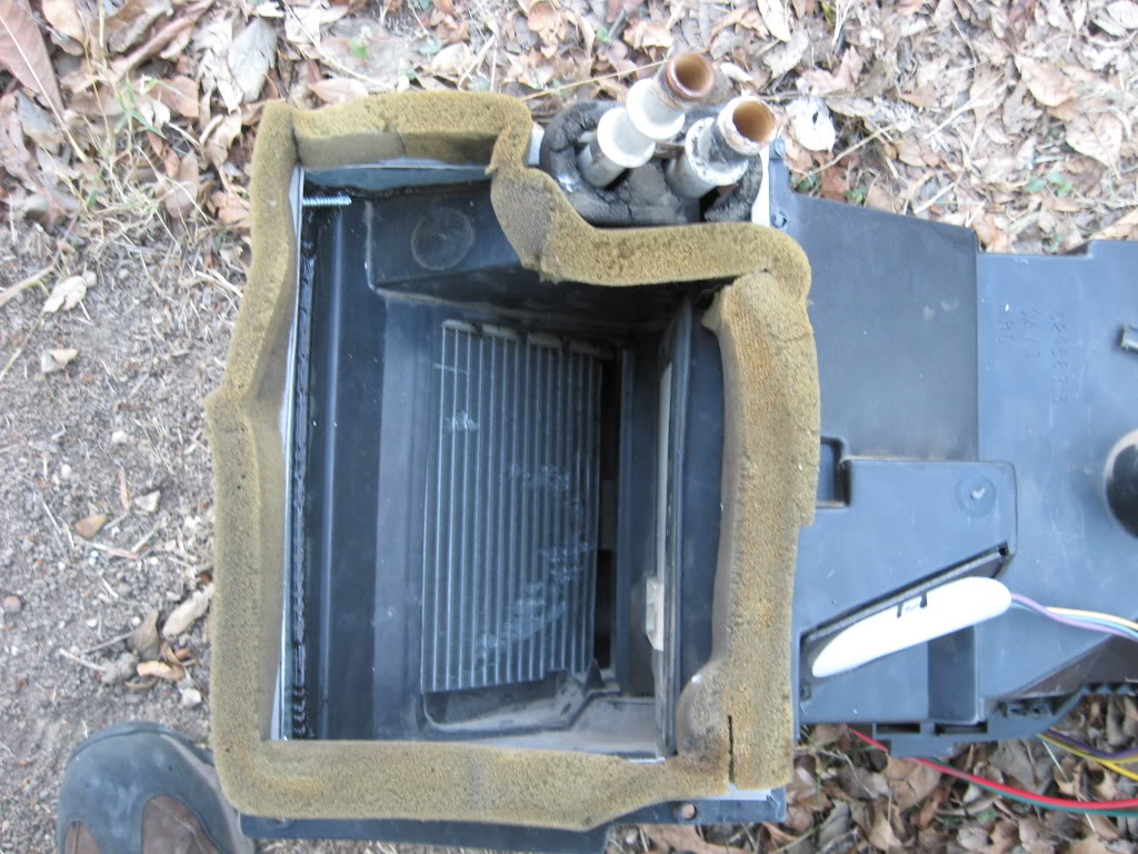
Now test fit your heater ducting to the firewall again, checking from the engine side that your foam seals around the edge of your firewall heater opening. If it doesn't, this can be fixed with a piece of sheet metal on the engine side to re-size your opening. I'm planning on putting a sheet on mine to seal off the heater core tubes and clean up the appearance before installing my new A/C delete heater box (write up on its construction to follow soon). Once you are happy with your fitment, you can guesstimate the location of the 4th gen ducting's mounts and drill holes in the firewall from the engine side to put the mounting screws thru. This will mount it securely in place and ensure the ducting seals with the firewall, as well as firming up the install of your 4th gen dash. Be aware that the orange vacuum tube to the air recirc vent will have to be modified with the appropriately sized 3rd gen attachment, as the 4th gen vacuum valve is a different size tube. If you followed my steps, you should now have fully functional 4th gen vents.
Please be aware I have not tried to re-mount a 3rd gen A/C system to my firewall, and I do not know what modifications to the stock 3rd gen heater / A/C box would be needed to clear the new location of the heater core tubes and new firewall opening.
Luckily, with a little modification to both the firewall and the 4th gen ducting, it can be made to work and full function of the climate settings can be had. This modification was done to my 83 Z/28 Camaro with a 94 dash install, and is currently working. Materials needed are;
1/4" head self tapping sheet metal screws
20-22 gauge sheet metal (16" by 18" sheet minimum)
all purpose exterior rated 3hr rain-ready silicone caulk
2 sheets foam sheet (available at hobby/craft stores)
1" thick foam (can be re-used from the 3rd gen ducting)
air cutoff wheel
dremel tool
sheet metal cutters
sharpie marker
caulk gun
super glue
First, use the dremel to remove the excess material around the edges of the heater core end of the 4th gen heater ducting. This lip is not needed on our modification. Refer to the pictures below for how much to remove. Then begin testing for fitment by attaching the 4th gen ducting to the 4th gen dash and hold it in place with tape, and test fit the whole assembly as close to it's final mounting position as possible. Then use a sharpie marker to mark along the top of the firewall where the edges of the heater ducting will mate to the firewall. These will be your reference marks for measuring the placement of your modifications. Nothing too scientific here, best guesstimates seemed to work for me. Take the dash assembly back out and remove the heater ducting from the dash. Now place it against the firewall as best as possible (stuff will still be in the way, don't worry), and line it up with the marks. Now you can see how much of the 3rd gen air recirculation valve location will have to be removed for the 4th gen heater ducting to fit. Mark with the sharpie a vertical line at least 1/2" - 3/4" from the edge of the 4th gen heater ducting on the recirc, and again horizontally above the 4th gen ducting. The vertical line should be as close to without touching the edge of the recirc vent as possible.
Now mark lines straight to the firewall along the recirc housing. Your goal is to make a square cutout in the side of the housing, removing the 45 degree section completely. This will notch the housing so that the 4th gen heater ducting will fit next to it perfectly, without affecting the function of the cowl vent drain or recirc vent. After marking, remove the recirc vent so as not to damage it in our next step. Now take your air cutoff wheel and carefully cut along the lines you marked, going slowly and making gradually deeper passes. Do not try to deeply cut in one pass, you risk either cutting too far or going thru the firewall into the engine bay. After making all your cuts, test fit the 4th gen heater ducting. It should look something like this now.
If your 4th gen heater ducting now fits in the notch you just created, you're halfway done. Now you need to mark the location of your heater core tubes, and modify the firewall heater box opening slightly for the new placement. Using my pics as a basis and your ducting's fitment, mark the approximate location the pipes need to pass thru the firewall, and the base of your ducting's opening.
The lower part of the firewall opening should have to be lowered about 1 1/2" - 2", the right side about 1/2" down and 2" - 2 1/2" out, and the tubes should have a rectangular opening cut for them at the top of the opening about 1/2" in from the left, 1" tall, and about 2" - 3" long. Start small and test fit as you go so as not to make the openings too large. Be sure to check from the engine side of the firewall also, it makes perfect fitment much easier. DOUBLE CHECK YOUR MEASUREMENTS BEFORE YOU CUT. Use my pics as a GUIDE only. Once you have this done, you're ready to close up the notch in the air recirc vent housing. Take careful measurements and lay out the basic design 2-dimensionally on a piece of cardboard. You want to start with the large square vertical area first, the measure and lay out the upper horizontal area, and the firewall side large triangular area. The goal is to make a flat cutout that can then be folded into a three dimensional piece that will fit perfectly into the notch you cut in the air recirc vent housing. Be sure to leave a 1/2" - 3/4" tab at either end of the square areas, these will be the attachment points that fit over top of the air recirc vent housing and get attached with the self tapping sheet metal screws. Once your cardboard template fits properly, transfer the design to your piece of sheet metal either by tracing it or measuring it and re-drawing it. Be sure to mark your fold lines, this will help when you cut it out and bend the metal later. Use sheet metal cutters and go carefully, also making sure to cut at least an 1/4" on all your folds to help them stay lined up. Once the shape is cut out, use a sturdy straight edge and bend your folds to 90 degrees. Your finished sheet metal piece should match your cardboard test piece and fit perfectly into the notch in the air recirc vent housing. Don't worry if there are gaps in the edges, this is what the silicone caulk is for. Once you have the sheet metal piece in place, use a high speed drill and the self tapping sheet metal screws to screw it into place in the notch in the air recirc vent housing. Once the piece is mounted, use your silicone caulk and run a good bead along each edge of the notch, and down all the seams in your sheet metal piece. This is to ensure a good weather seal, as the air recirc vent housing also doubles as the water drain for the cowl vent. Fill any large gaps with excess silicone, but don't go crazy. Do not try to smooth out the silicone, once the dash is in place you won't see it so prettiness isn't an issue, and if you spread it too thin it may not seal properly and you will end up with a water leak behind your dash. You finished product should look similiar to my first pic.Now you're ready to modify the 4th gen heater ducting itself. You should have already removed the excess trim around the edge of the heater core section, and you're left with the uneven firewall mating surface. Use a dremel or hobby knife to remove the excess material on the firewall mating surface, with the goal of making the topmost edge (even with the heater core tubes) as flat as possible. Now use cardboard again to make a template for your sheet metal pieces that will fill in the lower section of the firewall mating surface to make it even. You can use one large piece bent at the two corners, or make three separate pieces and join them together with self tapping sheet metal screws or pop rivets. I used three pieces as I was limited on the amount of sheet metal I had left, but it can be made from a single piece. Use my pics as reference for your end goal.
Again, think nice, flat even surface. Be sure to make tabs on the edges to attach the sheet metal to the heater ducting, and use your silicone again to seal everything up, otherwise you'll have air leaks and lose air pressure within the ducting (resulting in poor ventilation). Once the sheet metal is in place, measure the size of the outer rim on your new firewall mount, and cut two same size shapes out of your hobby foam sheets to glue to the top of the sheet metal and ducting. They should be 1/4" wider overlap both sides that the surface they will be sitting on, 1/2" total width. I used silicone to glue it in place, as it helped it to seal. Be sure to give it time to set up before you try to attach the foam, and then let it dry before going any further. After it sets up you can add another bead of silicone around the outer edge to help it hold. Your last step is to take the 1" thick foam and superglue it onto the top of the foam sheet as a foam seal to mount against the firewall. It should go inside of the heater core tubes, and be attached back to itself to ensure a good softseal with the firewall.
Now test fit your heater ducting to the firewall again, checking from the engine side that your foam seals around the edge of your firewall heater opening. If it doesn't, this can be fixed with a piece of sheet metal on the engine side to re-size your opening. I'm planning on putting a sheet on mine to seal off the heater core tubes and clean up the appearance before installing my new A/C delete heater box (write up on its construction to follow soon). Once you are happy with your fitment, you can guesstimate the location of the 4th gen ducting's mounts and drill holes in the firewall from the engine side to put the mounting screws thru. This will mount it securely in place and ensure the ducting seals with the firewall, as well as firming up the install of your 4th gen dash. Be aware that the orange vacuum tube to the air recirc vent will have to be modified with the appropriately sized 3rd gen attachment, as the 4th gen vacuum valve is a different size tube. If you followed my steps, you should now have fully functional 4th gen vents.
Please be aware I have not tried to re-mount a 3rd gen A/C system to my firewall, and I do not know what modifications to the stock 3rd gen heater / A/C box would be needed to clear the new location of the heater core tubes and new firewall opening.
Last edited by 1983Chimaera; Jan 30, 2011 at 10:19 PM. Reason: typos - wrong measurement - oops
Thread Starter
Senior Member
Joined: Sep 2006
Posts: 573
Likes: 9
From: San Antonio, Tx
Car: 1988 Camaro IROC-Z
Engine: LB9 (305 TPI)
Transmission: 700R4
Axle/Gears: 2.73 Positraction
Re: 4th gen heater ducting done right
**UPDATE** I have since installed a factory 3rd gen A/C delete heater box in my car with the 4th gen ducting modification outlined above. The new location of the heater lines required cutting a rectangular hole in the upper flat part of the heater box, below the upper right mounting hole in the "tab". This does not interfere with the actual ducting at all, just clearing it. I have full fan control with my 4th gen HVAC head unit, and full vacuum valve function and climate zones. I have not tried to mount a 3rd gen factory A/C box, but the fact that the A/C delete will go in leads me to believe it would be a minor fiberglass "notch" modification at most to give clearance to the lines. Good luck!
Joined: Sep 2005
Posts: 6,258
Likes: 6
From: O'Fallon, MO
Car: 1991 Z28 convertible built 3/1/1990
Engine: Cammed 6.0L LSX
Transmission: T56
Axle/Gears: custom Ford 8.8", 4.10 gears
Re: 4th gen heater ducting done right
Can you post a picture of the hole on the delete box you made?
Supreme Member
iTrader: (4)
Joined: Mar 2009
Posts: 3,079
Likes: 4
From: Pepperell, MA
Car: 1987 Trans Am
Engine: LQ9/L92
Transmission: 4L60E
Re: 4th gen heater ducting done right
very good info, thanks for sharing. my 4th gen dash had already been modified to fit a 3rd gen by the previous owner, but I'm sure this will help a few others looking to tackle the swap on a fresh dash
Senior Member
iTrader: (2)
Joined: Jan 2007
Posts: 733
Likes: 1
From: jackson new jersey
Car: 1991 camaro vert
Engine: ls1 soon
Transmission: t56 soon
Axle/Gears: moser 12bolt 4.10 soon!
Re: 4th gen heater ducting done right
Sweet!! I was just thinking about this and thank you for doing the hard work for us
Thread Starter
Senior Member
Joined: Sep 2006
Posts: 573
Likes: 9
From: San Antonio, Tx
Car: 1988 Camaro IROC-Z
Engine: LB9 (305 TPI)
Transmission: 700R4
Axle/Gears: 2.73 Positraction
Re: 4th gen heater ducting done right
I'll take closer pics of the hole in the A/C delete box tomorrow. For now here's some I took a while back that should give an idea of placement.
 The diagonal line running from the Lokar trans dipstick to the upper corner of the Mallory Hyfire 6A box is the upper mounting flange of the A/C delete box. The circles just to the lower right of the Lokar trans dipstick is the 3rd gen heater holes (now blocked with sheetmetal and sealed with silicone). The rectangular plate with 2 small 9/32 head bolts is the 3rd gen mounting hole for the Heater Ballast Resistors. The 4th gen has this mounted in the interior of the 4th gen ducting, and I used that location instead. The block off plate is simply a piece of sheetmetal with 1/8" foamboard strips glued to the back to form a seal. The rubber cap at the lower right of the blower motor is the location of the A/C delete blower motor cooling vent. As I re-used my old factory A/C blower motor, the cooling vent tube does not match up to the A/C delete. Since my blower motor works perfectly, I saw no need to replace it with the A/C delete one. I did have to replace my blower squirrel cage with the A/C delete one, as the factory A/C one is too deep to fit in the A/C delete box. I had originally planned to make a custom heater box, since I really didn't expect to ever come across a factory A/C delete in the junkyards in South Texas, but I got lucky a few months back. I was impressed at how well it fit even after shifting the hole in the firewall, and how the lines ended up being -just- out of the way.
The diagonal line running from the Lokar trans dipstick to the upper corner of the Mallory Hyfire 6A box is the upper mounting flange of the A/C delete box. The circles just to the lower right of the Lokar trans dipstick is the 3rd gen heater holes (now blocked with sheetmetal and sealed with silicone). The rectangular plate with 2 small 9/32 head bolts is the 3rd gen mounting hole for the Heater Ballast Resistors. The 4th gen has this mounted in the interior of the 4th gen ducting, and I used that location instead. The block off plate is simply a piece of sheetmetal with 1/8" foamboard strips glued to the back to form a seal. The rubber cap at the lower right of the blower motor is the location of the A/C delete blower motor cooling vent. As I re-used my old factory A/C blower motor, the cooling vent tube does not match up to the A/C delete. Since my blower motor works perfectly, I saw no need to replace it with the A/C delete one. I did have to replace my blower squirrel cage with the A/C delete one, as the factory A/C one is too deep to fit in the A/C delete box. I had originally planned to make a custom heater box, since I really didn't expect to ever come across a factory A/C delete in the junkyards in South Texas, but I got lucky a few months back. I was impressed at how well it fit even after shifting the hole in the firewall, and how the lines ended up being -just- out of the way. Last edited by 1983Chimaera; Apr 7, 2012 at 12:05 AM. Reason: typo
Thread Starter
Senior Member
Joined: Sep 2006
Posts: 573
Likes: 9
From: San Antonio, Tx
Car: 1988 Camaro IROC-Z
Engine: LB9 (305 TPI)
Transmission: 700R4
Axle/Gears: 2.73 Positraction
Re: 4th gen heater ducting done right
 My 94 dash, center console, and hybrid door panel prototypes. The covering on my dash is the cardboard template for my dash cover. I'm planning on using MDF warped to shape, then covered with automotive grey vinyl. The door panels are still only prototypes, with notable trouble spots being the gaping holes where the trimming was done on the hinge side and at the bottom under the armrest, and custom door lock rod issues. The door speakers are functional, as is all the power accessories on the doors. The vinyl rectangle under the armrest on the door is a 3rd gen Firebird map pocket, and is mounted on both doors. Both doors close nice an tight, the 4th gen interior dew wipes were retained and seal beautifully, and the door handles are much easier to open the door with than the old pot metal 3rd gen ones (which I got tired of breaking and replacing!) The red seam between the side of the dash and the door jamb is going to be filled with the same grey vinyl as the dash cover. The car is still thoroughly a work-in-progress.
 Trending Topics
Thread Starter
Senior Member
Joined: Sep 2006
Posts: 573
Likes: 9
From: San Antonio, Tx
Car: 1988 Camaro IROC-Z
Engine: LB9 (305 TPI)
Transmission: 700R4
Axle/Gears: 2.73 Positraction
Re: 4th gen heater ducting done right
**UPDATE** Since I have the engine compartment of my '88 LB9 IROC-Z stripped down for cleanup and painting, I had the opportunity to compare the 3rd gen factory A/C suitcase to the 3rd gen factory A/C delete box, and how they fit around the 4th gen heater lines. It looks like the 4th gen lines WILL clear the A/C evaporator in the suitcase, but the suitcase housing will have to be notched. If you look at the upper right hand top mounting hole on the factory A/C suitcase, draw an imaginary line straight down, then another line straight right to just above the upper right side mounting hole. That is what must be notched for the lines to clear the suitcase. I would then use a piece of sheet metal cut and folded to fit, with self tapping sheet metal screws to attach it, and fiberglass over top of all of this (the sheet metal is for rigidity and shape). The notch would have a minimal effect on airflow within the unit, but allow full function climate control and A/C on a 4th gen dash. If anyone needs visual reference for what I've described above, let me know and I will take a picture with markings where the modification must be made.
Senior Member

Joined: May 2003
Posts: 744
Likes: 0
From: California
Car: '91 Firebird
Re: 4th gen heater ducting done right
I see a big problem with this setup. When water gets in through the mesh it's supposed to run down and drain through the passenger side fender. The notches you've made won't let the water do this, it will just get stuck there. And it looks like you didn't paint the new metal, so I think rust is going to be a major problem.
Thread Starter
Senior Member
Joined: Sep 2006
Posts: 573
Likes: 9
From: San Antonio, Tx
Car: 1988 Camaro IROC-Z
Engine: LB9 (305 TPI)
Transmission: 700R4
Axle/Gears: 2.73 Positraction
Re: 4th gen heater ducting done right
Sorry for the late reply, haven't been to this thread in a while.
To answer your concerns, the water drains perfectly. I haven't blocked the water flow, simply removed the 45 degree drain path with a 90 degree one (the photo gives a distorted view of it). The water still flows out the passenger side, and there is no problem with accumulation whatsoever. As for the metal, 1. I used stainless steel and 2. I painted it before final assembly. This setup has been in my car for several years now without issue, and I'm thinking of adding A/C back in using a third gen system (with a small notch in the A/C box to clear the 4th gen heater lines).
As for the door panel question, no thread yet. Still have to get back to working on them after a long hiatus, but the prototypes are holding up well. Still no sealing issues or real problems, tho the door lock rods have just enough tension to overcome my old '83 power door lock solenoids, so I'm stuck with manual locking/unlocking for now. When I revisit the panels I'll come up with a better solution, refine them a bit, and add a full walkthough. So far though I'm happy with the upgrade, and it's been far more comfortable to drive around in than anything the 3rd gen setup ever had to offer.

Thread Starter
Senior Member
Joined: Sep 2006
Posts: 573
Likes: 9
From: San Antonio, Tx
Car: 1988 Camaro IROC-Z
Engine: LB9 (305 TPI)
Transmission: 700R4
Axle/Gears: 2.73 Positraction
Re: 4th gen heater ducting done right
I've addressed how to add functional A/C several times above. Go back and re-read the thread.

Thread
Thread Starter
Forum
Replies
Last Post
1992rs/ss
NW Indiana and South Chicago Suburb
14
Jan 31, 2025 05:10 PM
1992rs/ss
Engine/Drivetrain/Suspension Parts for Sale
16
Jan 28, 2016 09:58 PM